Abstract
Firstly, this paper introduces the design of high frequency large stroke vibration table according to the applicable environment. Secondly, the three-dimensional solid model is established which is based on solidworks2012 environment. The kinematics and dynamics simulation of the shaking table model are carried out. The vibration test curve of the vibrating table is obtained, and the reason of the change of the vibration curve under different vibration frequency is analyzed. Finally, this paper concludes that this exciting scheme is feasible and effective.
1. Introduction
Vibration phenomenon is one of the most common phenomena in nature. Some objects such as buildings, machines, etc., will produce vibrations under internal or external excitation, the majority of mechanical vibration is harmful [1, 2]. Therefore, the study of vibration is not only conducive to improve the service life of machinery and equipment, but also help to improve production efficiency. There are two main types of traditional mechanical vibration tables: centrifugal and direct acting, their operating frequency range is 5 Hz to 100 Hz [3, 4]. The maximum displacement of a conventional mechanical shaking table is about 20 mm. Due to the limitation of mechanical structure, the traditional mechanical vibration table has the disadvantage of low upper limit frequency and mechanical clutter [5-7]. The traditional mechanical vibration table cannot be use for the dynamic performance test of high-frequency sensors. Vibration stroke and frequency are two important design parameters of the shaking table [2, 8]. One of the main reasons to limit the increase of vibration parameters is the size of the inertial load.
This paper studies a new type of mechanical vibration table – symmetrical crank slider shaking table. Through the simulation test of the symmetrical mechanical vibration table, it is verified that this vibration table has a great improvement in the vibration stroke and the vibration frequency compared with the general mechanical vibration table.
2. Structure and working principle
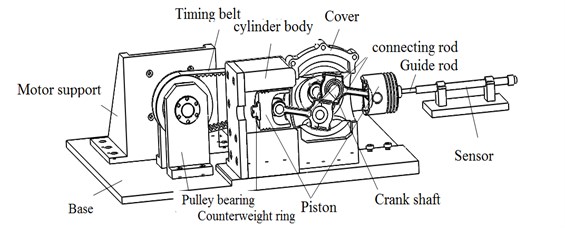
Fig. 1 shows the vibration system structure. The crankshaft is driven by the motor through the synchronous belt. The connecting rod is connected with the piston through the piston pin. Two pistons of the same material and size are reciprocally moved in the respective cylinder body, which is connected with the connecting rod. One of the pistons connected to the guide rod is used to output vibration. In order to balance the weight of the guide rod, a balancing weight is added to the opposite end of the piston.
The high frequency large stroke shaking table consists of four parts: the power source component, the excitation element, the parametric and the peripheral.
Assuming that the two crankshafts are in the same horizontal position as the initial position, the piston has the maximum amplitude at this moment. When crankshaft rotation is driven by the motor through the pulley and timing belt, the connecting rod drives the piston to move in opposite directions. When the crankshaft rotates to 180 degrees, the piston is in the reverse maximum amplitude. The piston returns to the initial position when the crankshaft continues to rotate to 360 degrees. This is a motion cycle, where one of the pistons is connected to the sensor via the guide bar to output vibrations.
Fig. 1Vibration system structure
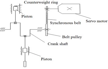
Fig. 2Shaking table structure
3. Design of excitations
The vibrator is the vibration generating device of the vibration table, and it is also one of the most serious parts suffering load. In order to reduce the inertia impact, lightweight should be taken into account. The vibrator structure is shown in Fig. 3.
Fig. 3Vibrator structure
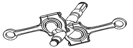
As shown in Fig. 3, the main structure of the vibrator consists of a crankshaft and two connecting rods. The connecting rod is connected with the piston, which is bound in the cylinder to do horizontal movement. The movement of the connecting rod is promoted by the crankshaft rotation, so that the rod head does horizontal reciprocating motion. The rotation of the crankshaft can produce a pair of forces of equal size and opposite directions. The piston is driven by this force to do reciprocating motion. For the whole vibration system, these two forces cancel each other. This is one of the main reasons for using a symmetrical crank slider. Fig. 4 shows the force of the connecting rod on the piston.
The center distance of the connecting rod directly affects the overall size of the shaking table, so it is a very important parameter in the design. Crank radius-connecting rod length ratio λ (λ=r/L) is generally greater than 0.3, so that the body height of the shaking table can be reduced and the net weight is reduced. However, too small crank radius-connecting rod length ratio will cause an increase in piston side pressure. This will lead to an increase in the friction loss of the body, thus accelerating the wear of the piston, piston ring and cylinder liner. In this way, the reliability of the system will be affected. In this paper, we determine λ= 0.3125, it means that the center distance of the connecting rod is 80 mm.
4. Mathematical model of vibration system
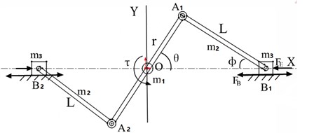
Dynamic model of vibration system is shown in Fig. 5. A symmetrical Crank connecting rod slide block is described in this figure.
Fig. 5Dynamic model of vibration system
The displacement equation of the piston can be described as:
Find the derivative of time for Eq. (1), then in the horizontal direction:
Speed is:
Acceleration is:
Constraints can be obtained by positional relations in Fig. 5:
Then the constraint equation is defined as:
5. Simulation of vibration system
According to the above working principle and the vibration body structure, the three-dimensional model of shaking table is successfully designed, as shown in Fig. 1. Based on the Solidworks2012 environment, the kinematic simulation analysis of the displacement, velocity and acceleration of the shaking table system at different frequencies is carried out.
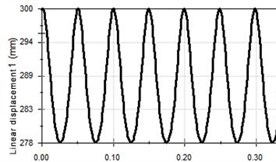
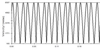
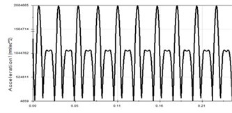
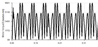
Kinematics and dynamics simulation are carried out at 20 Hz, 60 Hz, 100 Hz vibration frequency. Lightweight aluminum alloys are selected as the main material for the vibrating table. During the simulation, model constraints are added, servo motor is applied, and physical contact is set. Then we can get curves of the piston displacement, velocity, acceleration and crankshaft torque. These curves are shown in Fig. 6.
Fig. 6Vibration curve at 20 Hz
a) Displacement-time curve
b) Speed-time curve
c) Acceleration-time curve
d) Crankshaft torque
It can be seen from Fig. 6 that the displacement curve, the velocity curve and the acceleration curve of the piston are all in good shape. The amplitude is 25 mm, the stroke is 50 mm, the maximum speed is 3.291 m/s and the maximum acceleration is 520.416 m/s2. Due to the characteristics of the crank link structure, the acceleration will change rapidly, which is determined by the nature of the crankshaft. The piston vibration waveform will change further with the increase of the vibration frequency, as shown in Fig. 7 and Fig. 8.
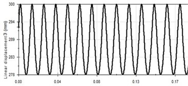
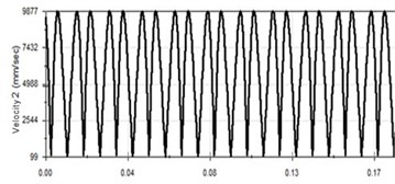
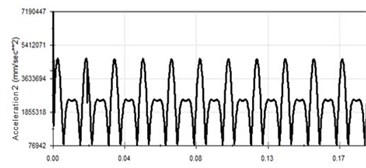
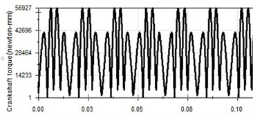
Fig. 7Vibration curve at 60 Hz
a) Displacement-time curve
b) Speed-time curve
c) Acceleration-time curve
d) Crankshaft torque
It can be seen from Fig. 7 that when the frequency is 60 Hz, the vibration period is further reduced and the vibration curve waveform does not change significantly. At 60 Hz, acceleration waveform has small fluctuations. The maximum speed v= 9.877 m/s, the maximum acceleration a= 4878 m/s2, and the maximum torque of crankshaft is 56.927 Nm.
Through Fig. 8, when the vibration frequency is 100 Hz, there is no significant change in the displacement curve and velocity time curve except that the cycle is gradually smaller. However, compared with the previous simulation, the acceleration trend has obvious changes. The piston acceleration is gradually increased and trend to stabilize in a period of time, but there are still small fluctuations. The maximum speed is v= 16.457 m/s, the maximum acceleration is 13624.848 m/s2. It is because the vibration frequency is relatively high, so the vibration of the body cannot be instantaneous acceleration. When the vibration frequency reaches the system set frequency, the acceleration curve tends to be stable.
Fig. 8Vibration curve at 100 Hz
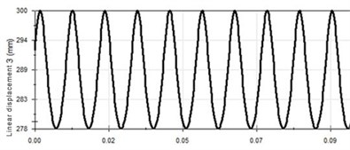
a) Displacement-time curve
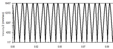
b) Speed-time curve
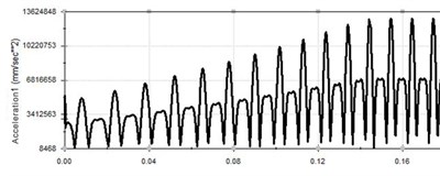
c) Acceleration-time curve
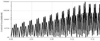
d) Crankshaft torque
6. Conclusions
1) Based on the working principle and system structure of the shaking table, the three-dimensional model is established, which proves the feasibility of this scheme.
2) Compared with the general mechanical shaking table, there is improvement in the mechanical structure. The effective stroke and the maximum vibration frequency of the mechanical vibration is effectively increased through this improvement.
3) The kinematics and dynamics simulation of the shaking table of the symmetrical crankshaft are simulated under different vibration frequencies. The simulation results show that the vibration table can be used at 0-100 Hz and the curve is not lost and jumped continuously. It is verified that the scheme of this symmetrical crank slider is true and feasible.
References
-
Gao Chunhua, Ji Jinbao, Yan Weiming, Li Na Development of seismic simulation shaking table technology in China. Journal of Civil Engineering Society, Vol. 47, Issue 8, 2014, p. 9-17.
-
Li Wei, Rong Ruanjian Experimental study on vibration characteristics of high frequency electro - hydraulic shaking table. Fluid Drive and Control, Vol. 3, 2013, p. 4-7.
-
Zou Zhenxing, Zou Beini Discussion on calculation method of basic parameters of centrifugal mechanical shaking table. Environmental Technology, Vol. 8, 2014, p. 57-61.
-
Wu Shangshegn, Huang Zexing, Lu Zhenwei, Zhou Yunqi Design and simulation analysis of shaking table with axial thrust roller excitation. Vibration and Shock, Vol. 2, 2014, p. 64-68.
-
Shi Qinglei, Yang Lizhi, Gao Feng, Ma Shulin Design of a small low - frequency standard shaking table. Earthquake Engineering and Engineering Vibration, Vol. 34, Issue 6, 2014, p. 256-263.
-
Hu Yong, Ling Mingxiang, Wang Jue Modeling and simulation of coupling dynamics of two degree of freedom swing table. Machine Tools and Hydraulic, Vol. 42, Issues 7-122, 2014, p. 124-128.
-
Tan Yonghua, Cai Guobiao Research on virtual simulation of shaking table. Mechanical Strength, Vol. 32, Issue 1, 2010, p. 30-34.
-
Cui Weiqing, Fan Shuncheng, Li Yanyan, Wang Shengkai Virtual prototype modeling and simulation analysis of hydraulic shaking table. Machine tools and hydraulic, Vol. 40, Issue 9, 2012, p. 141-143.

