Abstract
The purpose of this research is to replace thrusters (space components) used in space with spherical ultrasonic motors (SUSMs). If developing multiple thrusters with SUSMs, we will be able to save weight and as a result, downsize an artificial satellite. We successfully conducted a durability test of the SUSM under atmospheric pressure at high temperature in the prior research [1, 2]. In this research, we conduct a durability test of the SUSM at low temperature, and additionally, an experiment of temperature cycle repeating high temperature and low temperature. We conducted the durability experiment at –80°C in the low temperature environment, and achieved the accumulated driving hours more than 60 minutes as keeping the SUSM performance.
1. Introduction
Recently, advancement of science and technology has promoted researches in development of space technology, and many projects to develop an international space station and an artificial satellite have been going on. The important points of the artificial satellite design are downsizing and weight-saving, and they are of course, requirements for actuators. In this research, we develop a spherical ultrasonic motor (hereinafter, SUSM), which can be an alternative to the actuators currently used for the artificial satellites.
In space, an artificial satellite goes along a fixed orbit, as repeatedly receiving radiation heat from the sun and entering into the earth shadow where it receives no radiation heat. Therefore, a space SUSM must be capable of working at both high temperature and low temperature. The Japan Aerospace Exploration Agency (JAXA) conducts performance evaluation tests for space components under load with a temperature cycle of –120 to +120°C. In the prior research [1, 2], we developed a space SUSM that could be driven within the temperature range from normal temperature up to +120°C, and reported about it.
In this research, we conduct a drive test of the SUSM within the temperature range from normal temperature down to –120°C, and a temperature cycle experiment where low temperature environment and high temperature environment are alternately generated.
2. Spherical ultrasonic motor (SUSM)
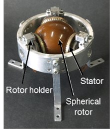
The SUSM can be driven with one motor at three-degree-of-freedom, and its simple structure helps downsizing. By using the SUSMs for the thrusters, we can easily control direction of the multiple thrusters loaded on the artificial satellite, and also reduce the number of thrusters to be loaded. In this research, on the assumption that the thruster jet to control the artificial satellite posture is performed once two weeks to one month, totally 20 times on average in a year, we assume that it emits a jet for about 20 seconds per one time, and durable years of the artificial satellite is 10 years. Therefore, we decide a target time of durability of the space SUSM as 60 or more minutes. The operable sizes for the artificial satellite thrusters are 30 mm in diameter of the stator and 45 mm in diameter of the spherical rotor, shown in Fig. 1, and we use them for development of the space SUSM.
Fig. 1Schematic of SUSM
3. Consideration at low temperature
In the prior research, we considered a piezoelectric element which the SUSM could drive at high temperature of 120°C and an adhesion bond. We achieved long driving hours with the use of NEC TOKIN’s piezoelectric element made from N6 material of which Curie point was 325°C, and the adhesion bond of ThreeBond, TB2285, of which glass transition point was 180°C. In this research, we consider how both of the N6 piezoelectric element and the adhesion bond TB2285, used for high-temperature support, can be maintained at low temperature, –120°C.
3.1. Consideration of piezoelectric element at low temperature
As an index for the piezoelectric element performance, the electromechanical coupling factor () is used. Since the SUSM’s piezoelectric element drives a rotor by elastic deformation with an elastic body, the Young’s modulus () of the piezoelectric element and the modulus of rigidity () of the elastic body also affect the piezoelectric element performance. We consider how these three factors, the electromechanical coupling factor, the Young’s modulus, and the modulus of rigidity, affect the piezoelectric element performance in the low temperature environment.
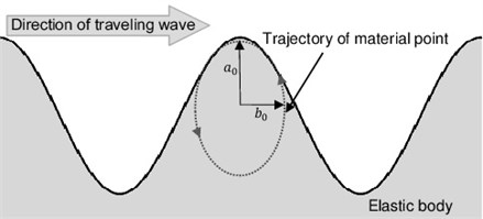
The SUSM is driven by traveling waves generated on the stator. By the traveling waves shown in Fig. 2, a mass point of the stator surface moves along an elliptical track of which longitudinal amplitude is , and horizontal amplitude is . The rotor is driven when this mass point and the rotor contact and generate frictional force.
It is known that even when temperature changes, the electromechanical coupling factor () is not affected, and the modulus of rigidity () of the elastic body increases when temperature goes down [3]. In other words, the modulus of rigidity () of the elastic body is considered to be the physical quantity that affects the longitudinal amplitude () of the stator surface mass point. Material of the elastic body of the piezoelectric element is phosphor bronze, of which modulus of rigidity is individually 40.2 GPa at normal temperature (22°C), and higher 43.1 GPa at low temperature (–197°C) [3]. However, the range of change in the longitudinal amplitude () at normal temperature and low temperature is lower than several percent. It is estimated that the stator surface mass point decreases in both the longitudinal amplitude and horizontal amplitude due to decrease in temperature, and accordingly, torque and the number of rotation decrease. However, the value of the SUSM shows that there is no influence even at high temperature and low temperature because the SUSM has originally small amplitude. Therefore, even at low temperature, the piezoelectric element made of the same N6 material is available.
3.2. Consideration of adhesion bond at low temperature
An adhesion bond must have high shear strength and peel strength after hardening, and a high degree of hardness after hardening. These three capabilities must be maintained even at low temperature of –120°C. The adhesion bond TB2285 used for the N6 piezoelectric element for the space SUSM is made from heat-curable epoxy resin. Since there is not much data about low temperature resistance capacity, the document about change in the shear strength and the peel strength of the general adhesion material made from epoxy resin [4] is used as reference for estimation.
Generally, epoxy resin has a high degree of elasticity, and is hard and fragile. Characteristically, while the shear strength of the epoxy resin becomes larger in proportion to a degree of elasticity of the adhesive agent, the peel strength becomes smaller. In order to increase the peel strength, the adhesion bond must be applied thickly. Nevertheless, capacity improvement of the peel strength is limited due to a finite gap of a body to be applied in the piezoelectric element. In other words, for the adhesion bond of the SUSM, the shear strength is particularly an important factor. Every epoxy resin adhesion bond, the shear strength indicates a constant value up to –253°C from 150°C, the value is smaller trend at 150°C or more. From here onwards, it is considered that the shear strength and the peel strength of the adhesive agent TB2285 are maintained also in the low temperature environment, similarly in the high temperature environment. Concerning a degree of hardness, since general materials are more and more hardened as temperature goes down, it is considered that the adhesion bond TB2285 is also gradually hardened along with the decrease in temperature. Therefore, the same adhesion bond TB2285 can be used in the low temperature environment.
Fig. 2Traveling wave
4. Durability experiment for SUSM in low temperature environment
4.1. Experiment method
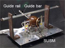
Fig. 3 shows an experiment device used for this experiment. A guide rail and a guide bar restricted the SUSM’s driving direction. This restricted driving system applied the largest load on the SUSM. The SUSM was reciprocated at an angle of 110 degrees (±55 degrees against the vertical direction), which was the drivable range, toward the direction restricted with the guide rail for 20 seconds, and its behavior was filmed with a video camera, then the number of rotations was calculated based on the number of frames in the video image. After the 20 seconds of driving, it was stopped for 10 seconds, and again, driven for 20 seconds, and this cycle was repeated to measure the changing rotation speed for the accumulated driving hours. During driving, temperature of the stator was measured with a K-type thermocouple. Also, impedance of the piezoelectric element attached to the stator was measured with an impedance analyzer (4294A, a product of Agilent Technologies).
In this experiment, a constant temperature bath (N-382, a TCL-type product of Shimadzu Corporation) was used. This device can change temperature in the range from 320°C to –180°C, with an internal heater for heating and an external tank (SP-120, a product of JECC TORISHA) which emits liquefied nitrogen gas to the inner side for cooling, and be controllable with dedicated software on a PC. In this experiment, the experiment device shown in Fig. 3 was installed inside of the constant temperature bath. The SUSM’s wires were passed through from the lower part of the bath, and connected to the external motor driver, and the dedicated controller drove the SUSM.
Fig. 3Experimental apparatus of SUSM for space
4.2. Target temperature setting in low temperature environment
In this experiment, the low temperature environment was created with liquefied nitrogen gas which cooled the inner side of the constant temperature bath. However, freezing phenomenon was observed in a small gap between the stator and the rotor, which inhibited the SUSM’s operation. A supposable cause is moisture contained in outside air coming through the gap prepared at the lower part of the bath for the SUSM wiring, and moisture contained in outside air mixed for temperature adjustment at the time of gasification of liquefied nitrogen gas. On the other hand, when the SUSM runs and its vibration operates rotary motion of the spherical rotor, the SUSM’s stator generates heat deriving from vibration. Therefore, ice is generated while the SUSM is stopped, and melted when it is running. However, if the internal temperature goes down excessively, ice is not melted and remains, and accordingly inhibits the SUSM’s operation.
Then, in this experiment, the target temperature in the low temperature environment was set to –80°C, where the freezing phenomenon was not so influential and also the SUSM was fully drivable, and the driving experiment was conducted based on this target temperature. It is estimated that there is no actual risk of freezing in space even when temperature is low.
4.3. Experiment result
Fig. 4 shows the impedance at 20°C and –80°C. Similarly, at the normal temperature, the sharp impedance curve remained and the piezoelectric performance was maintained even at –80°C in the low temperature environment. Fig. 5 shows the SUSM’s rotation speed at –80°C. The SUSM achieved accumulated driving hours of 61 minutes and 20 seconds (approximately 180 reciprocating motions) at –80°C in the low temperature environment.
Fig. 4Impedance characteristics at 20°C and –80°C
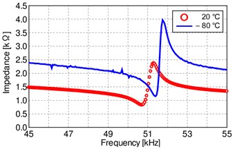
Fig. 5Rotation speed of SUSM at –80°C
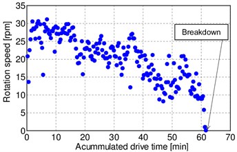
Fig. 5 shows that as time went by, the rotation speed went down step by step, and the SUSM stopped after 61 minutes and 20 seconds. The cause was influence of the ice residuals which remained even after heating because the motion was limited to reciprocating and therefore the ice generated between the stator and the rotor, or on the sliding surface was not melted. In other words, although driving stops after the accumulated driving hours of 61 minutes and 20 seconds at –80°C, if measures against resonance and freezing of the piezoelectric element are prepared, the accumulated driving hours can be vastly improved. On the other hand, it is considered if the same measures are prepared for the case where the target temperature goes down to –120°C, the original target temperature in the low temperature environment, the accumulated driving hours can be vastly improved. Since vacuum space does not generate ice in the SUSM, and the operation frequency of the thrusters is not so high, it is estimated that the SUSM can operate even at –120°C, the original target temperature in the low temperature environment.
5. Temperature cycle experiment for SUSM
5.1. Evaluation of torque with temperature cycle
We attached a pulley to the experiment device shown in Fig. 3 and used it. We attached a wire to the SUSM shaft, let the wire through the pulley out to the lower part of the constant temperature bath, and attached it to a spring balance. We read values of the spring balance while driving the SUSM, and calculated the torque. In this experiment, in order to use the external spring balance, we had to measure with the constant temperature bath opened. When the lower part was opened, the SUSM got frozen when temperature was –50°C or lower for the reasons described in the section 4.2. Accordingly, in this experiment, we assumed that the limit temperature in the low temperature environment was –50°C, and then, changed temperature within the range from –50°C to 120°C and evaluated influence of the temperature change to the torques.
We prepared the temperature cycle consisting of three steps; first, rose the temperature from 20°C up to 120°C, then dropped it from 120°C down to –50°C, and again, rose it from –50°C up to 20°C. We assumed that the temperature changed slowly, 1.0°C/minute. We measured the torques at four points; 20°C, 120°C, 20°C at the time of cooling from 120°C to –50°C, and -50°C. Table 1 shows the result of the temperature cycle experiment. Although the torque went down at the high temperature limit of 120°C, the stable high torque appeared individually at 20°C in temperature rising, 20°C in temperature dropping, and the low temperature limit of –50°C. Therefore, it is estimated that the stable torque was obtained at the normal temperature to the low temperature environment where no freezing occurred, and even when the torque decreased due to rise in temperature, it recovered to the high level at the normal temperature.
5.2. Evaluation of the number of rotations with temperature cycle
We changed the temperature within the range from –80°C to 120°C, and measured the rotation speed of the SUSM by 10°C. We prepared the temperature cycle consisting of three steps; first, rose the temperature from 20°C up to 120°C, then dropped it from 120°C down to –80°C, and again, rose it from –80°C up to –20°C. Based on the assumption that temperature changed slowly, the temperature change was set to be approximately 1.6°C/minute including the measurement time. To measure the rotation speed, we filmed the SUSM operating for 20 seconds with a video camera, and found the rotation speed with the number of image frames. Also, we measured impedance of the piezoelectric element of the stator at each temperature environment.
Fig. 6 shows the impedance result. Since the impedance curves of the piezoelectric element at all temperature environments were sharp, it is considered that piezoelectric performance was maintained. Also, although there was a slight difference between the resonance frequency and the anti-resonance frequency at the same temperature level, 20°C, in the temperature cycle, it is estimated that the impedance feature was maintained in the temperature cycle where the temperature changed repeatedly, because the impedance peak values were almost same.
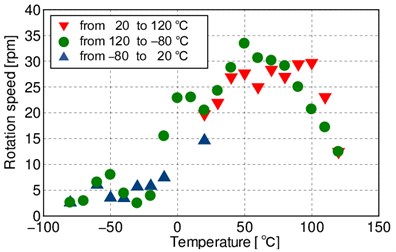
Fig. 7 shows the rotation speed results. At 20°C, immediately after starting, the high rotation speed was output, and over 100°C, the rotation speed rapidly went down. After that, although the high rotation speed recovered in the cooling cycle, the rotation speed decreased as the temperature went down. In the low temperature environment, the rotation speed was low and indicated almost constant values regardless of the temperature. We confirmed that the rotation speed recovered by increasing the temperature. On the other hand, a cause of the significant reduction in the rotation speed at the low temperature was supposedly the ice generated on the sliding surface. A large temperature difference inside the constant temperature bath due to the drop in temperature from the high level to the low level tended to generate ice. As a result, it is considered that freezing which should occur at sufficiently low temperature started around 0°C, and the generated ice rapidly decreased the rotation speed. Therefore, it is considered that the SUSM performance can be maintained in space where no freezing occurs.
Fig. 6Impedance characteristics in temperature cycle
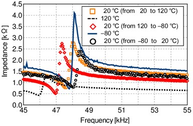
Fig. 7Rotation speed of SUSM in temperature cycle
6. Summary
In this research, we conducted the durability experiment in the low temperature environment and the temperature cycle experiment, which were tasks in the previous research for the purpose of maintenance of the SUSM performance.
We conducted the durability experiment at –80°C in the low temperature environment, and achieved the accumulated driving hours more than 60 minutes as keeping the SUSM performance. When the temperature cycle was given, the impedance performance to maintain piezoelectric performance in every temperature environment was confirmed, and moreover, the SUSM performance acquired from the high torque at the low speed area was confirmed both in the high temperature environment and the low temperature environment. On the other hand, in the temperature cycle experiment starting from the normal temperature, it was confirmed that the rotation speed indicated the low values in the high temperature environment and the low temperature environment, and recovered at the normal temperature. It is considered that the cause of the low values shown in the high temperature and the low temperature environments was the freezing phenomenon.
Since no freezing phenomenon occurs in space, we will conduct a temperature cycle experiment in a vacuum chamber in the future. Also, we aim to develop a SUSM that can resist acoustic vibration which a spacecraft receives immediately after lift-off, random vibration, and other various types of vibration, in addition to heat shock in the temperature cycle.
References
-
Nishizawa U., Oohashi T., Toyama S. Development of spherical ultrasonic motor for space. Evaluations of durability under high temperature environment. Vibroengineering Procedia, Vol. 6, 2015, p. 1-6.
-
Oohashi T., Nishizawa U., Fukaya N., Toyama S. Spherical ultrasonic motor for space. Proceedings of the 6th ICMDT, Vol. 15, Issue 204, 2015, p. 258-259.
-
Technical Documentation, the Module of Elasticity of the Metal Material. Japan Society of Mechanical Engineers, 1980, p. 141.
-
Adhesion Handbook First Edition. The Adhesion Society of Japan, Nikkan Kogyo Shimbun Inc., 1971, p. 559-561.
