Abstract
The DC600V electricity supply device plays an important role in locomotive. In this device, the main circuit is one kind of single-phase full-bridge half-controlled rectifier circuit. In this paper, first of all, we analyze the theory of main circuit. Secondly, accurate model is built through MATLAB/Simulink. We obtain the waveform of key parameters and harmonic analysis. The results of simulation waveforms show that the model is correct. It is proved that the built model flexible, convenient and intuitive. Meanwhile, it can be used for further fault detection and analysis.
1. Introduction
The DC600V electricity supply device, which provides various electrical devices on passenger train with electric energy, plays an important role in HXD locomotive. Thus, the working condition of electricity supply device has direct influence on electricity consumption of passenger train and the reliability of device is of great importance. Such power electric device, which works under condition of high-power and heavy load, suffer from structure faults or parameter faults frequently. In addition, the poor working condition in locomotive with continuous vibration and high temperature intensify damage to the device. In fact, the main circuit of the device is a kind of single-phase full-bridge half-controlled rectifier circuits. In the past decades, some researchers have given more theoretical research and developed varieties of techniques on analog circuit analysis and fault diagnosis [1-4]. However, lots of theoretical researches have significant differences with actual engineering applications. Some simulation models do not fully reflect the real situation [5, 6]. Only the model is established accurately, simulation results can be obtained more realistic. One of the characteristic of the circuit is that, it consists of load of resistance and inductance, rather than load of resistance. Output voltage contains large pulsation is the defect of resistive load. Inductance can control the amplitude of the voltage waveform [7].
In this paper, we have analyzed the key components of the device and simulated main circuit with accurate parameters, which consists of load of resistance and inductance. Firstly, we analyze the property of key components and parameters, such as output voltage and harmonic analysis. Secondly, we contribute the model of main circuit and then simulate kinds of condition of circuit with MATLAB. The work can provide useful information for the further study on device fault diagnosis, prognostics and health management (PHM) [8, 9].
The remainder of the paper is organized as follows. Section 2 briefly reviews the basic theory of the circuit and harmonic analysis. In Section 3, main circuit of device is simulated by MATLAB. The simulation results are drawn also in this section. Finally, this paper is summed up in a conclusion in Section 4.
2. Circuit theoretical analysis
2.1. Main circuit of the device
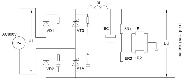
The main circuit of electricity supply device can be simplified as Fig. 1. VT1 and VT4 constitute a pair of bridge arm, and VT2 and VT3 constitute the other pair of bridge arm.13L is inductance, while 19C is the circuit capacitance.
The average value of the output DC voltage is [10]:
Effective value of output voltage is:
Fig. 1The main circuit of the device
2.2. Harmonic analysis in the circuit
Single-phase bridge rectifier circuit average output voltage and harmonic voltage are [11]:
The ratio of the amplitude of the nth harmonic voltage to the AC voltage amplitude of the single-phase bridge circuit is:
The phase angle of the nth harmonic is:
Effective value of the harmonic voltage is:
The ripple coefficient of the voltage is:
Voltage total harmonic distortion rate is:
3. Simulation and results
The simulation model of single-phase full-bridge half-controlled rectifier circuit based on MATLAB 9.1.0 is shown in Fig. 2.
Fig. 2Simulation model of the rectifier circuit
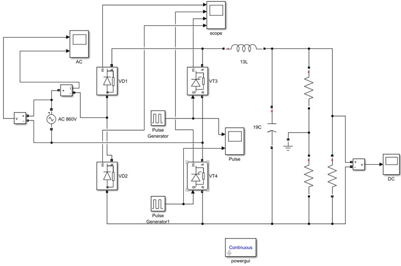
Table 1Key parameter of circuit
Component | Parameters |
AC 860 V | Peak amplitude 860*sqrt (2) V; Frequency 50 Hz |
13L | Inductance 9.8e-3H |
Load R | R= 1 Ohms |
VD1, VD2 | Forward voltage Vf 0.8 V; Resistance Ron 0.001 hms |
VT3, VT4 | Forward voltage Vf 0.8 V; Resistance Ron 0.001 hms |
Generator | Pulse width 0.25 %, period 0.02; phase delay 55° |
The key parameters of components in simulation are shown in Table 1.
Parameters of the model have been set, and the algorithm Ode23tb has been selected. Simulation time continues 0.5 s. The waveform of AC link, output voltage, pulse waveform, VD1, VT4, VD 2and VT3 have been shown in Fig. 3-Fig. 9, respectively. Fig. 10 shows the results of harmonic analysis.
In Fig. 3, we can see that, the waveform of voltage in AC link is sinusoidal wave, while current waveform is saltatorial, because of thyristors’ break-over and cut-off in a period. Fig. 4 is normal output voltage waveform in DC link. According to the requirement, voltage fluctuates between 570 V and 630 V. In Fig. 5, the first pulse of VT4 triggers at 0.003 s, and then VT4 conducts. After 0.01 s, generator of VT3 acts. Owing to these thyristors work with interval,
Fig. 3AC link current and voltage
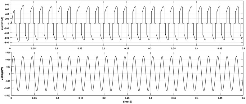
Fig. 4Normal waveform of output voltage
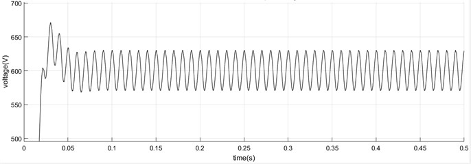
Fig. 5Pulse generator
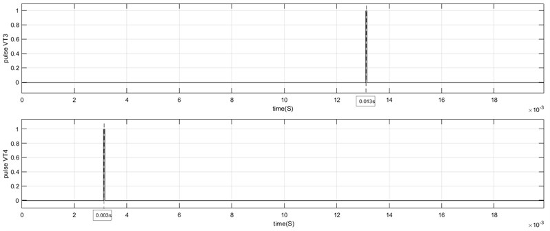
Fig. 6Current and voltage waveform of VD1
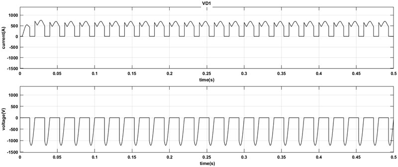
Fig. 7Current and voltage waveform of VT4
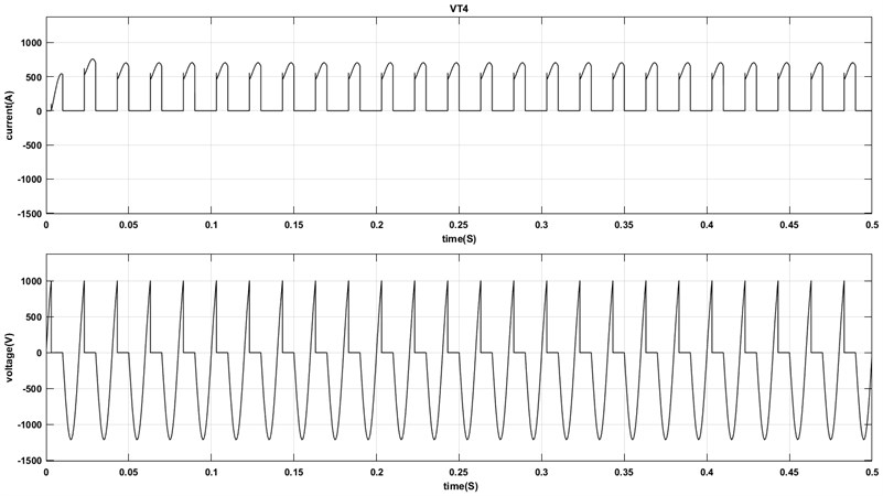
Fig. 8Current and voltage waveform of VD2
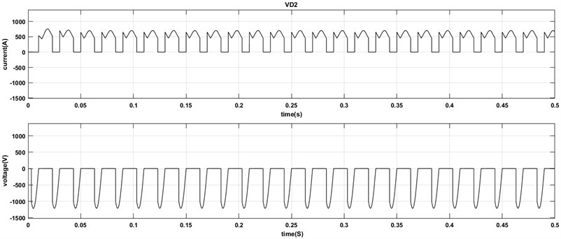
Fig. 9Current and voltage waveform of VT3
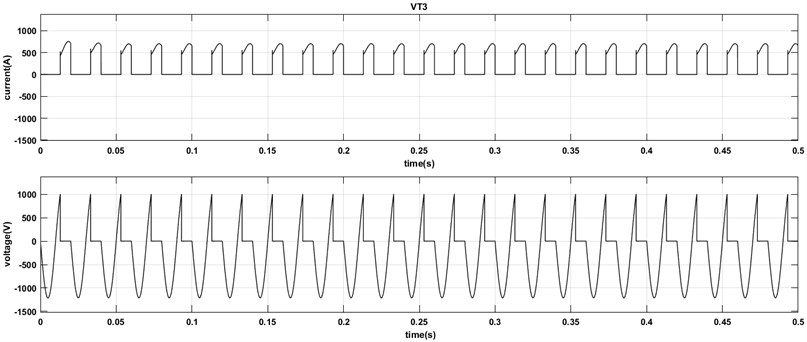
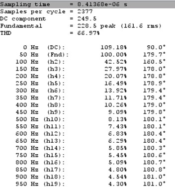
In Fig. 6-Fig. 9, waveform of VD1and VD2, VT3 and VT4 are similar with each other respectively, except phase difference. Fig. 6 and Fig. 8 shows that, diode can sustain negative voltage while current is 0, but when the voltage is 0, the current is positive. Fig. 7 and Fig. 9 shows that, voltage in thyristor likes the sin wave but is cut off when this element conducts, at this period the current is significant nonzero values. As shown in the Fig. 10, harmonic analysis with MATLAB, the THD is 66.97 %.
Fig. 10Harmonic analysis
4. Conclusions
In this paper, first, we analyze the theory of single-phase full-bridge half-controlled rectifier circuits, involving output voltage value and harmonic analysis. And then, we simplify the main circuit of device and build the accurate Simulink model with MATLAB/Simulink environment. Each parameter has been validated to ensure the accuracy of the model. After model establishment, using the MATLAB/Simulink tool simulate and obtain the results, which have been consistent with the theoretical analysis. Using this model, parameters of the circuit can be changed flexibly, which can be used to analyze fault condition and prognostic of main circuit.
References
-
Mohagheghi S., Harley R. G., Habetler T. G., Divan D. Condition monitoring of power electronic circuits using artificial neural networks. IEEE Transactions on Power Electronics, Vol. 24, Issue 10, 2009, p. 2363-2367.
-
Mohagheghi S., Harley R. G., Habetler T. G., Divan D. A static neural network for input-output mapping of power electronic circuits. IEEE International Symposium on Diagnostics for Electric Machines, Power Electronics and Drives, Cracow, 2007, p. 329-334.
-
Cai Chi, et al. A Fault Diagnosis method used for the three-phase full-bridge rectifier circuit. IEEE International Symposium on Computer, Consumer and Control, 2016.
-
Choi Sanghun, Saeedifard M. An educational laboratory for digital control and rapid prototyping of power electronic circuits. IEEE Transactions on Education, Vol. 55, Issue 2, 2012, p. 263-270.
-
Wu Yi, et al. Multiple parametric faults diagnosis for power electronic circuits based on hybrid bond graph and genetic algorithm. Measurement, Vol. 92, 2016, p. 365-381.
-
Tan Han Hong, Zhao X. A simulation research on single phase bridge full control resistive load rectifying circuit based on MATLAB. International Conference on Advanced Materials and Information Technology Processing, 2016.
-
Guo Quan, et al. Research on Modeling and simulation of power electronic circuits based on MATLAB. Applied Mechanics and Materials, Vols. 687-691, 2014, p. 3106-3109.
-
Su Wen-Jing, Zhu Hu Simulink in rectifier circuit application and simulation. Journal of Ningbo Polytechnic, Vol. 2, 2007, p. 5-7.
-
Jia Zhou, Wang Jinmei The study on single phase bridge controlled rectifier circuit at the based of MATLAB. The World of Power Supply, Vol. 6, 2009, p. 33-35.
-
Xie Peng, et al. The Simulation Study of Single-phase and Voltage-type Inverter Circuit for Half-Bridge Based on MATLAB. Electronic Technology, 2015.
-
Xie Tao, et al. The Modeling and Simulation of Single-Phase Bridge Type Rectifying Circuit Based on MATLAB. Electronic Technology, 2014.
