Abstract
This paper presents a digital implementation of modified synchronous reference frame in which the Phase Locked Loop (PLL) is customized to get the angle for the reference frames from the supply voltage by Enhanced Phase Locked Loop (EPLL). The extracted harmonics currents are given to an Artificial Neural Network based Space Vector Pulse Width Modulation (ANNSVPWM) which has better switching control and reduced stress on the switches to cancel the distortions at the Point of Common Coupling (PCC). The algorithm was modelled and simulated by Matlab/Simulink to validate the results. The experimental verification is carried on Field Programmable Gate Array (FPGA) Spartan board to check the effectiveness of the control strategy being implemented and the results conclude that the Total Harmonic Distortion (THD) values are below the required levels of power quality standards.
1. Introduction
Owing to the increased usage of power electronic equipments for the control of electrical drives and implementation of sophisticated control systems in industries it is inevitable that harmonics are generated by these loads, the supply is made more distorted and harmonics produced by these nonlinear loads are added to the electrical system which makes our supply more polluted. The order and magnitude of the harmonics depend on the configuration and system impedance. These harmonics cause undesirable effects on the electrical equipments such as increased reactive power consumption [1], reduced power factor, increased losses in the electrical device which leads to more heating and reduced life of the product, computers develop error due to data loss or control process in an industry to fail. These power quality problems must be mitigated and should be within the levels specified by IEEE 519 and IEC 61000 which are universal standards for power quality.
For the mitigation of harmonics various techniques has been proposed such as the passive filter or active filter. Passive filters have drawbacks such as resonance problem with the electrical system, the system becomes bulkier, switching of passive elements cause power quality problems and passive elements are used for the reduction of harmonics of particular order, they are designed for lower order odd harmonics whereas the remaining harmonics are present in the system. The rating of the filter must be coordinated with the reactive power need for different load conditions [2]. To prevail over these drawbacks active filters has been proposed in the literature which can eliminate harmonics of any frequencies or of any order. By the purging of harmonics, the reactive power is compensated the power factor of the system is improved and the THD of the system is greatly abridged.
Active filter consists of a Voltage Source Inverter (VSI) which injects current in opposite direction at PCC, for the measurement of harmonics various techniques has been proposed such as instantaneous reactive power (PQ) theory. Synchronous Reference Frame theory (SRF), synchronous detection method, Icosφ algorithm, symmetrical component theory, instantaneous active and reactive compensation theory (dq) [3, 4]. The extracted harmonic currents are given to Pulse Width Modulation (PWM) switching technique to generate pulses for the injection of compensation current by the VSI. Different PWM techniques have been discussed such as the hysteresis band PWM, Sine PWM, space vector pulse width modulation.
In this paper a novel control algorithm for the extraction of harmonics using SRF theory with modification in the PLL with EPLL. The drawback of conventional PLL is under adverse grid conditions the grid voltage is unbalanced or harmonically distorted and due to this high amplitude steady state oscillations occurs in the estimated phase and frequency; this causes degraded performance of the PLL [5]. Using the EPLL control technique the accuracy of the extraction of harmonics is improved and THD value is reduced at PCC. The output of the PLL is at the same frequency as that of the input voltage, the dynamic response of the system is improved, and the EPLL operates satisfactorily in the presence of unbalances and harmonics.
Fig. 1Block diagram of EPLL based shunt active filter
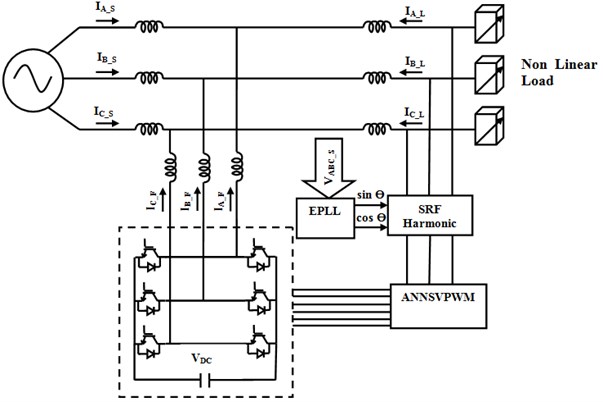
It uses the transformation of all the three phase voltages by reference frame transformation and to compute the positive and negative frames to implement the EPLL. The signals obtained from the output of EPLL are sin and cos angles which are used for the transformations that are synchronized with the fundamental positive sequence component. The computed harmonic content in the three phases is given as input to the ANNSVPWM as shown in Fig. 1.
The ANNSVPWM has to generate pulses for the VSI to generate the compensation current to be injected at PCC to cancel the harmonics. The drawback of conventional Space Vector Pulse Width Modulation (SVPWM) is it has lower switching frequency, the computational complexity is also more and it uses look up table which takes more computation time [6]. In the proposed ANNSVPWM technique the angle and amplitude are computed and given to a multilayer feed forward neural network in which back propagation is used for computing the duty cycles of space sectors used for the generation of PWM pulses for the VSI. It has advantage of faster implementation and the switching frequency of the power switches can also be increased [7]. In this paper the EPLL algorithm along with ANNSVPWM is implemented on a digital FPGA Spartan board which has advantages of faster implementation, the switching frequency of the inverter is also increased.
2. Modified SRF based harmonic extraction
For the extraction of harmonics from the load current various algorithms have been proposed in the literature, the most popular is synchronous reference frame theory (SRF) and it has advantage of ease of execution, robust performance for ideal conditions when the load current is harmonically less distorted [8]. In unbalanced and distorted load conditions SRF method of harmonic current extraction is less effective. To trounce these drawbacks EPLL has been proposed in this paper. The load current and source voltage are measured by means of current and potential transformer. The measured three phase load current are converted in to two axis stationary coordinate system using Clarke transformation:
Fig. 2Block Diagram of Modified Synchronous Reference Frame based PLL
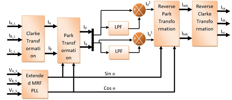
The reference frames in the stationary coordinate system are transformed to the synchronously rotating reference frame using Eqs. (4) and (5). The currents Id and Iq represent the direct and quadrature axis of the distorted load current:
The two axes synchronously rotating reference frame is passed through a low pass filter to filter out the average component of the current and pass through the pulsating component of the current present in the load current [9]. The filtered harmonic current is transformed to stationary reference frame as given in Eq. (6) and (7):
The reference current in two axis is transformed in to three axes by reverse Clark transformation. The currents in two-phase coordinates are transformed into three-phase coordinates as given in the Eqs. (8) to (10):
The current in the three phase coordinates represents the extracted harmonic content of the supply currents and the current to be injected to the VSI depends upon the difference between the harmonic content of the signal and the injected current of the active filter.
3. Extended MRF PLL
The angle θ for the Park and Inverse park transformation is generated by the Phase Locked Loop (PLL) which synchronizes the output signal in frequency and phase with the input. In unbalanced and distorted conditions to enable fast and accurate phase and frequency detection EPLL is used for obtaining the instantaneous information of the phase angle and the magnitude of the signal [10]. The PLL detects the phase, filters out the unwanted signal and the oscillations are produced by the voltage controlled oscillator [11]. The input voltages which are unbalanced are transformed into dq synchronous reference frame:
The feedback loop regulates the dq reference frame. The three phase system is taken as unbalanced and harmonically distorted [11]. The positive sequence and negative sequence of the harmonics are present at the input.
In EPLL has two synchronous reference frames rotating in opposite directions at the equivalent angular speed. The fundamental positive and negative sequence components are separated from the fundamental frequency [5]. The error caused by the negative sequence component is eliminated.
Vd gives an estimation of the amplitude of the positive sequence component and Vq gives information of the negative sequence component, both rotating in opposite directions at the equivalent angular speed [12]. Of the input signal. When the frequencies are locked the negative sequence component input voltage appears as disturbance input to the PLL oscillating at twice the fundamental frequency.
4. Artificial neural network based space vector PWM
PWM signals are used for modulating the time duration of the pulses to provide a compensation current in opposition the current harmonics present at PCC [13]. The SVPWM represents the three phase space vector as one rotating quantity which can be easily implemented in digital systems for both transient and steady state conditions [14]. The ANNSVPWM measures the amplitude and angle of the reference frame to generate the gating pulses. The measured harmonic component of the current is fed as input to the ANNSVPWM which acts as a feed forward neural network for nonlinear mapping system. The input is converted in to direct axis and quadrature axis components Vd and Vq. The magnitude and angle are separated by Cartesian to polar conversion of the two axis components [7]. The ANN is used to calculate the time periods for the angular position of the different sectors in the reference frame. The computational burden of customary SVPWM to check the look up table for calculating the time delays is reduced by using ANNSVPWM [6]. The neural network is trained using Eqs. (17-18) and the ANN model is generated and placed using simulink. The turn on time for the three phase inputs are given by the following equations:
f(V*) → Voltage amplitude scale factor.
g(α*) → Turn on Signal at Unit Voltage:
The time of application of the different sectors is found using voltage second principle. The sector is detected by comparing the angle with predefined values. The neural network takes α* as reference voltage position. Multilayer neurons are used in the first and second layer and the number of nodes, the weights are set in the training stage.
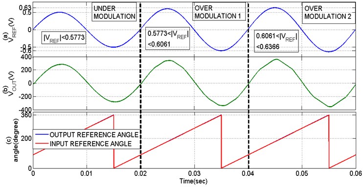
As shown from the Fig. 3 the three different modulation regions are split up into every 0.02 sec. Furthermore, the three different modulation regions limit and the relevant input reference magnitude change response is shown in Fig. 3(a). Based on the input magnitude variation the output of the space vector is linearly varied is depicted in Fig. 3(b). The ANN based theta extraction reduce the computation delay results in the phase angle difference of input and output of the SVPWM is completely eliminated is shown in Fig. 3(c). The input and output reference angle is overlapped as shown in the analysis under different modulation regions of the space vector.
Table 1ANN based SVPWM training
1st Layer | 12 Neuron (Log Sig) | Input Layer | |
2nd layer | 12 Neuron (Log Sig) | Hidden layer | |
3rd Layer | 3 Neuron (Purelin) | Output layer | |
Training Error | 0.53 % | ||
Training Epoch | 98430 | ||
Fig. 3Comparison of ANNSVPWM under different modulation regions
5. Result and discussion
A three phase laboratory prototype model has been developed to validate the results obtained by the simulation using Matlab/Simulink. The hardware is developed using an iron cored source inductor of 150 µH for low frequency, ferrite core made compensation inductor of 2 mH of high frequency. The DC link capacitor is 1500 µF electrolytic type, DC link voltage is 230 V, the voltage source inverter module is an 2 KW smart power module FSB 20 CH, the controller used for the implementation of control technique is FPGA Spartan 6, the nonlinear load connected is a bridge rectifier of 600V, 35 A having a inductor of 24 mH. The sensor used for the measurement of current is CT 15 A / 1 A with a resistance of 220 Ω, 5W connected in parallel, the sensor used for sensing the voltage to be given to the EPLL is LV 25 – P and the hardware is designed for a switching frequency of 10 kHz.
The proposed method was simulated and the output of simulation shows that the nonlinear load draws a distorted load current from the supply mains which have to be filtered by the active filter and converted in to a pure sinusoidal current at PCC. The three phase sinusoidal voltage is applied to the nonlinear load as shown in Fig. 4.
As illustrated in Fig. 5 the load current of the three phases is distorted due to the presence of a bridge rectifier connected which acts as a nonlinear load.
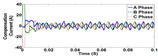
The three phase non sinusoidal load current is analysed to compute the harmonics present in the signal using the proposed harmonic extraction technique using EPLL with ANNSVPWM and compensation currents are injected in to the electrical system at PCC as shown in Fig. 6.
Fig. 4Three phase sinusoidal voltage

Fig. 5Three phase load current
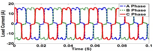
Fig. 6Compensation current
When compensation current is applied at PCC the non-sinusoidal load current is converted in to a sinusoidal wave shape reducing the non-linearity of the source current as shown in Fig. 7.
The harmonics present at PCC are removed by active filtering, the THD present in the load current is within the limits specified in power quality standards and the reactive power and power factor of the system are improved as shown in Fig. 8.
Fig. 7Source current vs load current

Fig. 8PF of the System at PCC

The output of the proposed control algorithm implemented on a FPGA Spartan 6 which has advantages of faster implementation, parallel operation of many process and higher switching frequency. For maximum utilization of the FPGA resources the parameter declaration of bias, the weight of the neural network must be within the specified ranges with the data obtained from the training in Matlab to obtain the required parameter and to declare the maximum and minimum calculation ranges [9].
The ANNSVPWM algorithm is used for calculating the duty cycles of the switches for the different angles of the reference space vector and the computation of harmonics based on modified synchronous reference theory is implemented using EPLL technique for improved accuracy and faster implementation. The source voltage and source current of the proposed hardware for all the three phase output is shown in Fig. 9.
Fig. 9Source voltage and current of three phase
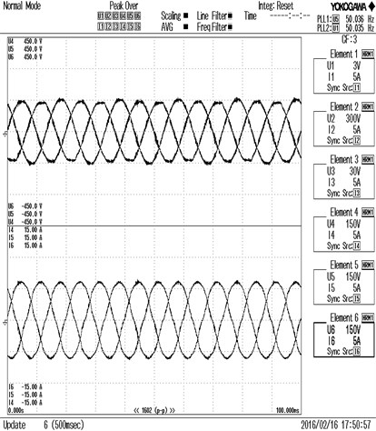
Fig. 10Voltage, source current, compensation current and load current for R phase
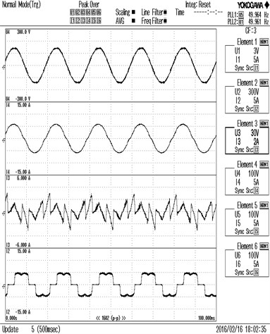
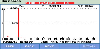
Fig. 11THD of source current
In Fig. 10 the source voltage, source current and compensation current of one phase of the three phase electrical circuit is given. The distorted load current due to the nonlinear loading arrangement is shown in Fig. 10. The non-linearity of the current wave form causes increase in reactive power losses and reduced power factor. These disturbances are removed effectively by injecting compensating current at PCC and the source current is made sinusoidal in shape and the reactive power losses are reduced and the PF of the system is also improved.
The experimental results conclude that the THD of load current of the three phases was 38.4 % before the application of shunt active filter and after the implementation of control algorithm in the proposed hardware the THD is reduced as shown in Table 2, these values are below the required level of power quality standards.
Table 2Tabulation of SAF parameters
Parameters | R Phase | Y Phase | B Phase |
Vrms Voltage | 106.78 | 106.06 | 106.8 |
Irms Current | 4.3794 | 4.3652 | 4.3418 |
PF | 0.9934 | 0.9875 | 0.9950 |
I THD | 1.7 % | 1.8 % | 2.2 % |
V THD | 0.87 % | 0.89 % | 0.88 % |
VDC | 221.76 V | ||
6. Conclusions
The implementation of modified SRF based EPLL and ANNSVPWM based switching of SAF on FPGA Spartan 6 hardware and the output results are verified with the simulation results simulated using Matlab/Simulink. The results confirm that the proposed system has better performance compared to the existing control techniques; the THD of the system is improved and is within the limits specified by various power quality standards. In the hardware the response time was faster and the implementation of control algorithm was done less than a cycle, the PF of the system is improved at PCC and maintained near unity. Filtering of THD is made more accurate by using EPLL technique.
References
-
Xu Lin, Han Yang, Khan M. M., Zhou Lidan, Yao Gang, Chen Chen, Pan Jumin A novel control strategy for dynamic voltage restorer using decoupled multiple reference frame PLL (DMRF-PLL). WSEAS Transactions on Systems, Vol. 8, Issue 2, 2009, p. 261-277.
-
Kesler Metin, Ozdemir Engin Synchronous-reference-frame-based control method for UPQC under unbalanced and distorted load conditions. IEEE Transactions on Industrial Electronics, Vol. 58, Issue 9, 2011, p. 3967-3975.
-
Bhat Abdul Hamid, Agarwal Pramod An artificial-neural-network-based space vector PWM of a three-phase high power factor converter for power quality improvement. Proceedings of India International Conference on Power Electronics, 2006.
-
Bhattacharya Avik, Chakraborty Chandan A shunt active power filter with enhanced performance using ANN-based predictive and adaptive controllers. IEEE Transactions on Industrial Electronics, Vol. 58, Issue 2, 2011, p. 421-428.
-
Pereira Rondineli Rodrigues, da Silva Carlos Henrique, da Silva Luiz Eduardo Borges, Lambert Germano Control of PWM rectifier under grid voltage dips. Bulletin of the Polish Academy of Sciences, Technical Sciences, Vol. 57, Issue 4, 2009, p. 337-343.
-
R. Zahira, Fathima Peer A. A technical survey on control strategies of active filter for harmonic suppression. Procedia Engineering, Vol. 30, 2012, p. 686-693.
-
Xiao Peng, Corzine Keith A., Venayagamoorthy Ganesh Kumar Multiple reference frame-based control of three-phase PWM boost rectifiers under unbalanced and distorted input conditions. IEEE Transactions on Power Electronics, Vol. 23, Issue 4, 2008, p. 2006-2017.
-
Guo Xiao-Qiang, Wu Wei-Yang, GuHe-Rong Phase locked loop and synchronization methods for grid interfaced converters: a review. Przegląd Elektrotechniczny (Electrical Review), Vol. 87, Issue 4, 2011, p. 182-187.
-
Golestan Saeed, Monfared Mohammad, Freijedo Francisco D. Design-oriented study of advanced synchronous reference frame phase-locked loops. IEEE Transactions on Power Electronics, Vol. 28, Issue 2, 2013, p. 765-778.
-
Chaoui Abdelmadjid, Krim Fateh, Gaubert Jean-Paul, Rambault Laurent DPC controlled three-phase active filter for power quality improvement. Electrical Power and Energy Systems, Vol. 30, 2008, p. 476-485.
-
Mikkili Suresh, Panda A. K. Real-time implementation of PI and fuzzy logic controllers based shunt active filter control strategies for power quality improvement. Electrical Power and Energy Systems, Vol. 43, 2012, p. 1114-1126.
-
Erfidan Tarık, ButunErhan Low cost implementation of artificial neural network based space vector modulation. Springer, LNCS, Vol. 3611, 2011, p. 204-209.
-
Kumar Subash C. S., Gopalakrishnan V. Design of synchronous reference frame based harmonic detection and space vector pulse-width modulation based switching of shunt active filter. Australian Journal of Electrical and Electronics Engineering, Vol. 10, Issue 3, 2013, p. 362-370.
-
Zaveri Naimish, Chudasama Ajitsinh Control strategies for harmonic mitigation and power factor correction using shunt active filter under various source voltage conditions. Electrical Power and Energy Systems, Vol. 42, 2012, p. 661-671.

