Abstract
The traditional wheel loader is built without any axle suspension and experiences severe vibration. Three different layouts of hydropneumatic suspension, namely, unconnected strut (UCS), interconnected in roll plane (IC-R) and interconnected in roll and pitch plane (IC-RP), are installed on the wheel loader to improve ride comfort. This study mainly focuses on the damping effect of different layouts of suspensions and investigates whether the suspensions will affect the driving and operation stability of the wheel loader. The multibody model of the wheel loader with hydropneumatic suspension is developed by RecurDyn in co-simulation with MATLAB/Simulink. Detailed analysis was performed as the wheel loader was traveling on a C-class road, turning on a flat road, and scooping and unloading crushed rocks. Results showed that (1) the three layouts of suspensions can greatly reduce the vector sum of weighted acceleration; (2) the UCS suspension affects both the driving and operation stability of the wheel loader, and the IC-R suspension affects the operation stability when the wheel loader scoops and unloads crushed rocks, (3) the IC-RP suspension with anti-roll and anti-pitch functions has little effect on the driving and operation stability of the wheel loader.
1. Introduction
Articulated wheel loader has two separate parts that are connected by a vertical steering pin. The relative yaw angle between these two parts is changed by two hydraulic cylinders when the driver turns the steering wheel. Unlike vehicles designed primarily for transport, the wheel loader is built without any axle suspension. The front wheels are attached directly to the front body, and the rear axle is allowed to oscillate around the longitudinal axis, thus allowing all wheels to maintain contact with the ground. A schematic diagram of wheel loader is shown in Fig. 1. Wheel loaders are engineering vehicles used for various tasks and their working environment consists of irregularly shaped materials such as fragmented rock, sand, or soil. Given the primitive vehicle design and unstructured roads, wheel loaders experience severe vibration and poor stability, which seriously affects the driver's health and operating efficiency [1-3].
Fig. 1Structure outline of a traditional wheel loader

Many studies have shown that designing a vehicle with fully suspended wheel axles is the most efficient way to reduce vibrations [4, 5]. However, relatively fewer studies have attempted to investigate the design and conduct performance analyses of axle suspensions installed on the wheel loaders. This situation may mainly be attributed to the strong couplings between ride comfort and operation stability properties of the wheel loader. The most common loading operations of the wheel loaders are (a) scooping from a pile, (b) traveling to a dump truck, and (c) unloading in a truck, as shown in Fig. 2. The axle load varies widely during loading operation. The load on the front axle will increase approximately three to four times in a loaded wheel loader, whereas the rear axle load decreases to approximately two thirds of the static axle load in an unloaded vehicle. This condition affects the pitching inertia of the vehicle. Hence, a suspension for a wheel loader must be able to handle this large range of axle loads; otherwise, the elastic deformation of the suspension system may affect the operational accuracy of the working device.
Fig. 2Operating process of the wheel loader

Rehnberg [6] developed the virtual multibody models of a wheel loader with and without axle suspensions to investigate the effect of introducing axle suspension on vehicle ride performance. The simulation results revealed approximately 50 % reduction in the longitudinal and vertical accelerations through front and rear axle suspensions. Pazooki [7] described a novel torsio-elastic linkage suspension concept and investigated its ride dynamic characteristics for articulated wheel skidder through field measurements and simulations. In comparison with the unsuspended vehicle, the prototype suspended vehicle resulted in nearly 35 %, 43 %, and 57 % reductions in the frequency-weighted RMS accelerations along the x-, y-, and z-axis, respectively. The addition of an axle suspension system to articulated wheel vehicles could yield significant reductions in the magnitudes of transmitted vibration to the operator seat. However, previous studies paid little attention to the impact of axle suspension systems on vehicle operation and driving stability. Rehnberg [8] only studied the snaking stability of articulated wheel loaders with axle suspension, which showed that an axle suspension may have a slightly destabilizing effect; this effect can be offset by a stiffer or more damped steering system. The axle load of the wheel loaders varies widely during the “scooping-traveling-unloading” cycle; the center of gravity will shift upwards during lifting, whereas the articulated steer frame decreases its stability when turning with laterally displaced center of gravity. Hence, considering the scooping, traveling, unloading, and turning stability after the axle suspension system is added on the articulated wheel loaders is important.
In this paper, three hydropneumatic struts, namely unconnected strut (UCS), interconnected in roll plane (IC-R) and interconnected in roll and pitch plane (IC-RP), are developed to investigate the ride comfort, the driving stability and operation stability of the presented wheel loader. This paper is organized as follows. Section 2 describes the wheel loader with hydropneumatic suspension and builds the multibody simulation model. Section 3 presents the generalized forces for the three hydropneumatic struts. Section 4 describes the simulation conditions. Section 5 analyzes the ride comfort and stability of the wheel loader with different suspension struts. Section 6 presents conclusions.
2. Vehicle modeling
The modern articulated wheel loaders are built without any axle suspension; thus, severe vibration and poor stability is experienced when on an unstructured road. This study proposes a wheel loader with hydropneumatic suspensions for the improvement of ride comfort, as shown in Fig. 3. The hydropneumatic suspensions are installed on the front and rear axles. The axles are subjected to large load when the loader is in operation; thus, non-independent suspension structures are adopted to ensure sufficient strength.
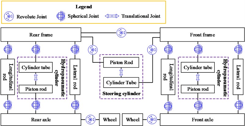
The proposed wheel loader with suspension is modeled using the multibody dynamics software RecurDyn (FunctionBay, Inc., Korea). RecurDyn can give good performance in large-scale multibody problems. Yao [9] built a virtual prototype model of the articulated vehicle by using RecurDyn, which was verified by field experiments. The results showed that the simulation results are consistent with the experimental results. The graphical representation of the front and rear suspension is shown in Fig. 4. The front axle is attached to the front frame using the hydropneumatic cylinder, where one spherical joint connects the front axle to the cylinder rod, and the other connects the cylinder tube to the front frame. The piston rod and the cylinder tube are constrained by a translational joint. Furthermore, longitudinal and lateral rods, which are connected to the front frame and the front axle through spherical joints, are used to carry longitudinal and lateral forces in the axle suspension. The rear axle and the rear frame are connected in the same manner as the front ones. The front and rear frames are constrained by a revolute joint; the relative yaw angle between these two parts is changed by two steering cylinders. In order to compare the impact of suspension on the comfort and stability, the traditional wheel loader without suspension (WS) is also modeled. The front axle is rigidly attached to the front frame, and the rear axle is mounted on a rotating joint allowing the axle to pivot relative to the rear frame.
Fig. 3Structure of the articulated wheel loader with hydropneumatic suspension
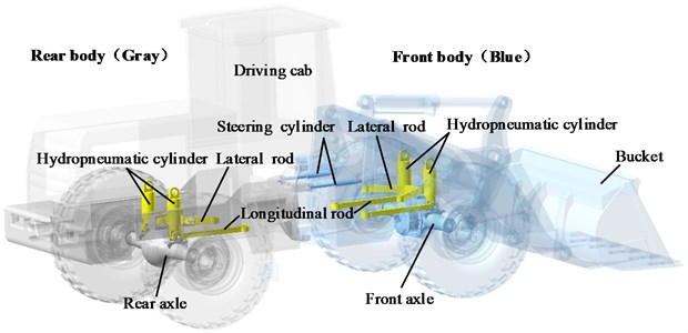
Fig. 4The graphical representation of the front and rear suspension modelled in RecurDyn
The Fiala tire model is applied in this dynamic model, and it described the relationship among the lateral, vertical, and longitudinal forces, the slip angle, and the slip ratio of the tires; this model has been verified by experiments [10]. Table 1 shows the parameters for the Fiala tire model [11]. Table 2 shows the dimensions and specifications of the developed wheel loader model. The center of gravity position and the moment of inertia are all relative to the global coordinate system o-xyz, which is located at the middle of the steering pin, as shown in Fig. 1, and x axis coincides with the forward direction, z axis is parallel to the inverse direction of gravity and y axis is determined by the right-hand rule.
Table 1Fiala tire model properties
Parameter | Value |
Unloaded tire radius | 0.875 m |
Vertical tire stiffness | 4.8×10⁶ N/m |
Longitudinal tire stiffness | 9.7×10⁶ N/m |
Later tire stiffness by slip angle | 2.9×10⁶ N/deg |
Tire radial damping ratio | 0.75 |
Friction coefficient at zero slip | 0.6 |
Coefficient of rolling resistance | 0.08 |
Table 2Parameters of the wheel loader model
Parameters | Meanings and units | Value |
m | Total mass (kg) | 17970 |
ms | Suspended mass (kg) | 14200 |
mu | Unsuspended mass (kg) | 3770 |
G(x,y,z) | Centre of gravity position (m) | (–0.255, 0, 0.233) |
Ixx | Roll moment of inertia (kg∙m2) | 30015 |
Iyy | Pitch moment of inertia (kg∙m2) | 97500 |
Izz | Yaw moment of inertia (kg∙m2) | 98100 |
B | Tread (m) | 2.20 |
lf | Distance between the steering pin and the front axle (m) | 1.53 |
lr | Distance between the steering pin and the rear axle (m) | 1.90 |
The axle load of the wheel loaders varies widely during scooping and unloading. The discrete element method (DEM) is used for simulating the scooping and unloading processes to analyze the effect of the suspension system on the performance of the wheel loader. The DEM is one of the numerical methods for computing the motion of a large number of particles, which are the micrometer-scale size and above. Particles Module in RecurDyn can be used to build particles and the DEM is applied to solve many particles. The scooping and unloading performance of the wheel loader depends on several factors, such as material properties, shapes, and sizes. This study cannot fully cover various factors, thus only the crushed rock as the scooping object of the wheel loader is selected. Table 3 shows the properties of the crushed rock [12].
Table 3Calibrated material properties
Parameters | Value |
Particle radius | 0.03 m |
Particle density | 1518 kg/m3 |
Poisson’s ratio | 0.3 |
Normal stiffness | 1.75×10⁷ N/m |
Friction coefficient | 0.53 |
3. Analytical models of the hydropneumatic suspension systems
Hydropneumatic suspension can achieve the functions of anti-roll, anti-pitch and balance shaft load through different interconnection struts. This paper mainly analyzes the three different forms shown in Fig. 5, namely, unconnected strut (UCS), interconnected in roll plane (IC-R) and interconnected in roll and pitch plane (IC-RP). All the calculations in this section are performed under the following assumptions and conditions [13, 14]:
(1) The influence of the ambient pressure is neglected. This condition is acceptable, because the usual working pressure levels in the cylinders, as well as the pre-charge pressures of the accumulators, are significantly higher than the ambient pressure.
(2) The friction between the piston and the cylinder is also negligible.
(3) All hydraulic pressures do not include pressure losses (e.g., caused by flow restrictors).
(4) The liquid is incompressible.
Fig. 5Layouts of hydropneumatic suspension
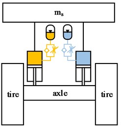
a) UCS
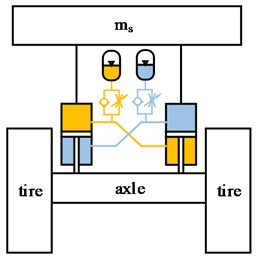
b) IC-R

c) IC-RP
3.1. Analytical model of unconnected strut
Fig. 6 shows the unconnected hydropneumatic suspension, the cylinder is connected to the accumulator. In the compression stroke, the oil flows from the cylinder through the throttle and check valve into the accumulator. In the extension stroke, the oil flows from the accumulator through the throttle valve to the cylinder.
Fig. 6Unconnected hydropneumatic suspension
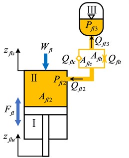
The volume flow rates through the orifices are related to pressure differentials across the orifices in the following manner:
where, Cd is the discharge coefficient; Afl3 is the orifice area and consists of the area of the check valve and throttle valve, Afl3=Aflc+Aflt, the opening pressure of the check valve is Pflc; ρ is the mass density of the fluid; Pfl2 and Pfl3 are the real-time pressures in chamber Ⅱ and chamber Ⅲ, respectively; Pfl23 is the pressure differential across the damping restriction, Pfl23=Pfl2-Pfl3; and the sgn function describes the direction of the fluid flow:
The pressure differentials, Pfl23, due to orifice flows in the left and right suspension units are obtained from Eq. (1) as:
According to the continuity equations, we can obtain that:
The rate of change of the fluid volume in hydraulic cylinder is related to the relative velocity across the respective strut:
where, ˙zfls and ˙zflu are the velocities of the cylinder tube and the piston rod of the front left hydropneumatic cylinder, respectively.
Upon substituting for Qfl3 from Eq. (4), the pressure differentials across the orifices are related to the piston velocities in the following manner:
Before calculating the spring force of the hydropneumatic suspension it is necessary to define some of the various states that a suspension system can be in:
State 0: The pressure in the accumulator is the precharge pressure P0fl3, which is defined during the production process. The gas fills out the complete internal volume V0fl3, of the accumulator.
State 1: Now the static suspension force Wfl is loading the suspension system. The force is sufficient to compress the gas volume in the accumulator isothermally to the volume VIfl3 and the pressure PIfl3.
State 2: Ffl is the dynamic suspension force and oscillates around Wfl. Therefore, the gas volume is compressed (compression) and expanded (rebound) by a polytropic change of state to the volume VIIfl3 and the pressure PIIfl3.
The starting point for the calculation is the correlation of the force Wfl acting onto the surface of the piston:
Assuming static pressure in the connected chambers is identical:
Upon combining Eqs. (7) and (8), the fluid pressure in chamber Ⅲ in state 1 can be expressed as:
On the basis of the isothermal change of state from 0 to 1 it is stated:
Using the state equation for polytropic changes of state:
VIIfl3 can be expressed as:
Upon combining Eqs. (5), (10), (11) and (12), the fluid pressure in chamber Ⅲ in state 2 can be expressed as:
PIIfl3 represents the real-time pressure in chamber Ⅱ, for the following calculation it can be applied that:
Upon combining Eqs. (6), (13) and (14), the fluid pressure in chamber Ⅱ can be expressed as:
The force developed by the hydropneumatic suspension is derived from the force acting on the piston:
3.2. Analytical model of interconnected strut
Although the interconnected suspension IC-R and IC-RP have different suspension struts, the forces developed by each strut can be conveniently derived using a unified form. The mathematical formulations for the strut forces of IC-R is presented as examples, as shown in Fig. 7, while the strut forces of IC-RP could be developed in a similar manner using the generalised model. To facilitate the description, the “front-left,” “front-right,” “rear-left,” and “rear-right” are abbreviated as “fl,” “fr,” “rl,” and “rr” in the subscript of the symbols, respectively. For example, Ffl represents the suspension force of the front-left strut.
Fig. 7Schematic representations of the interconnected hydropneumatic suspension
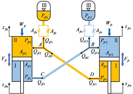
According to the continuity equations, we can obtain that:
where, ˙zfrs and ˙zfru are the velocities of the cylinder tube and the piston rod of the front right hydropneumatic cylinder, respectively.
According to the form of Eq. (15), the pressures in chamber Ⅰ and chamber Ⅱ of IC-R can be expressed as:
The fluid pressure in chamber Ⅲ in state 1 can be expressed as:
Assuming laminar fluid flows through the interconnecting pipes, and negligible entry and exit losses, the volume flow rates through the pipes linearly relate to the pressure differentials in the following manner:
where, QAD is the volume flow rate from chamber Ⅱ of the front left strut to chamber Ⅰ of the front right strut, and QBC is the volume flow rate from chamber Ⅱ of the front right strut to chamber Ⅰ of the front left strut.
The coefficient K in Eq. (20) can be expressed as:
where, D is the diameter of connecting pipes, L is the length of connecting pipes, μ is the dynamic viscosity of fluid.
According to the continuity equations, we can obtain that:
Upon combining Eqs. (20) and (22), the fluid pressure in chamber Ⅰ can be expressed as:
The forces developed by the interconnected hydropneumatic suspension are derived from the forces acting on the pistons:
The suspension characteristics are based on a set of physical parameters such as, static load, charge pressure and volume, orifice area, length and diameter of interconnection pipe. These parameters are presented in Table 4. Each of the parameters are selected based on identical load carrying capacity, static deflection and static stiffness at design ride height.
Table 4Simulation parameters of hydropneumatic suspension
Symbols | Description | UCS | IC-R / IC-RP |
Wfl,Wfr | The static load acting on the front suspension struts | 33600 N | |
Wrl,Wrr | The static load acting on the rear suspension struts | 37000 N | |
μ | Dynamic viscosity of fluid | 0.6 Ns/m2 | |
ρ | Mass density of fluid | 850 kg/m3 | |
Cd | Discharge coefficient | 0.62 | |
n | Polytropic coefficient | 1.3 | |
P0fl3,P0fr3,P0rl3,P0rr3 | The initial charge pressure in the suspensions | 2 MPa | 4 MPa |
V0fl3,V0fr3,V0rl3,V0rr3 | The initial charge volume of gas in the suspensions | 0.0026 m3 | 0.0015 m3 |
Afl1,Afr1,Arr1,Arl1 | Piston rod side area | / | 0.0054 m2 |
Afl2,Afr2,Arr2,Arl2 | Piston head area | 0.01 m2 | 0.01 m2 |
Aflt,Afrt,Arrt,Arlt | Orifice area of throttle valve | 2×10⁻⁴ m2 | 2×10⁻⁴ m2 |
Aflc,Afrc,Arrc,Arlc | Orifice area of check valve | 5×10⁻⁴ m2 | 2×10⁻⁴ m2 |
Pflc,Pfrc,Prrc,Prlc | Opening pressure of check valve | 0.25 kPa | 0.1 MPa |
L | Length of connecting pipes | / | 1.5 m |
D | Diameter of connecting pipes | / | 0.03 m |
The hydropneumatic suspension is modelled using Matlab/Simulink (MathWorks, 2012) and provides the RecurDyn full vehicle model with a suspension force via co-simulation, as shown in Fig. 8. The RecurDyn vehicle model is linked with Simulink and Matlab using the RecurDyn/Communicator interface. RecurDyn vehicle model exports the vehicle dynamics variables (velocities and displacements of the cylinder tubes and piston rods) to Simulink. These variables are then used to calculate the suspension forces which are sent back to Recurdyn via Simulink.
Fig. 8Co-simulation interaction

4. Driving conditions and evaluation
4.1. Driving conditions
4.1.1. Traveling on rough road
The International Organization for Standardization (ISO) has proposed a series of standards of road roughness classification using the Power Spectral Density (PSD) values [15], as shown in Table 5. The road displacement PSD can be described as:
Here, n is the space frequency (m−1) and time frequency f=nv (v is the vehicle speed), n0 is the reference space frequency, G(n) is the road displacement PSD, G(n0) is road roughness coefficient shown in Table 5, w is the linear fitting coefficient, always w= 2. Based on the standard road surface description, the road surface input model has been built through an inform filter by Gaussian white noise and successfully used in many presented works [16, 17]. The equation of road surface input is:
where f0 is low cut-off frequency, f0= 0.065 Hz, G0 is road roughness coefficient, U0 is vehicle speed, ω0 is a Gaussian white noise.
Wheel loaders are engineering vehicles and their working environment consists of irregularly shaped materials such as fragmented rock, sand, or soil, so the C-class road (poor) was selected in this paper.
Table 5Road roughness values classified by ISO (Gn0×10−6)
Road class | Range | Geometric mean |
A (good) | 8-32 | 16 |
B (average) | 32-128 | 64 |
C (poor) | 128-512 | 256 |
D (very poor) | 512-2048 | 1024 |
4.1.2. Turning on a flat road
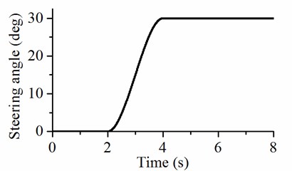
The input of the steering angle is 30°, as shown in Fig. 9. Turning on the flat road could be accomplished by analyzing the steering stability change of forward speed from 5 m/s to 7 m/s while maintaining the steering angle at 30°.
Fig. 9Inputs of the steering angle
4.1.3. Scooping and unloading
Scooping and unloading were performed by the loader working device, as shown in Fig. 10. The loader working has a front-mounted bucket controlled by two mechanisms: one is the lift arm driven by the lift cylinder, and the other is the rotation link driven by the bucket cylinder for rotating bucket. The performance of the working device mainly depends on the position of the nine hinge points of the A-I. Table 6 shows the initial coordinates of the nine hinge points in the coordinate system oxyz. The extensions of the lift and bucket cylinders at initial state shown in Fig. 10 are defined as zero.
Fig. 10Working device of the wheel loader
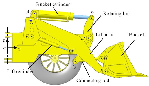
Table 6Initial coordinates of the nine hinge points in the coordinate system oxyz
A | B | C | D | E | F | G | H | I | |
x (mm) | 865.6 | 2701.0 | 752.6 | 2607.4 | 782.2 | 2003.3 | 2179.5 | 3021.3 | 3157.6 |
z (mm) | 1113.2 | 967.0 | 887.6 | 309.5 | 360.2 | –113.8 | –459.4 | –356.1 | –790.0 |
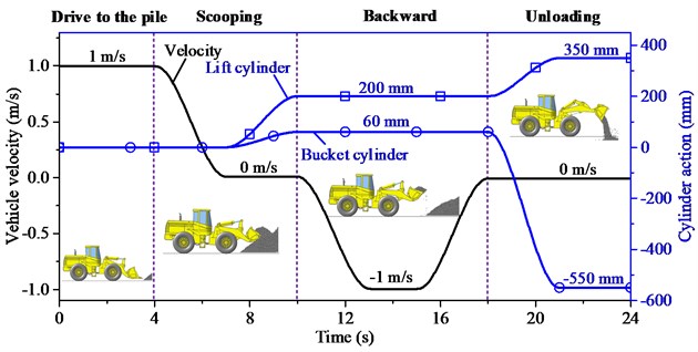
Fig. 11 shows the vehicle velocity, and the amount of expansion and contraction of the lift and bucket cylinders during operation. The entire operation process includes four stages: (1) Drive forward to the pile at the speed of 1 m/s. (2) Insert the bucket into the pile using the traction force of the vehicle; then, extend the bucket and lift cylinders up to 60 mm and 200 mm, respectively, to scoop the crushed rocks. (3) Drive the wheel loader toward the discharge location. (4) After reaching the discharge site, the lift cylinder continues to extend to 350 mm to lift the bucket, whereas the bucket cylinder retracts to –550 mm to flip the bucket for unloading.
Fig. 11Entire operation process
4.2. Evaluation
4.2.1. Ride comfort
The ride comfort is analyzed according to the ISO 2631-1 (1997) standard [18]. Accelerations are measured from the seat index point (SIP), which is located approximately at the same point as the hip pivot point of the driver. The ISO 2631-1 standard defines different methods for measuring the vibration, the basic evaluation method, calculation of the weighted running root mean square (RMS) acceleration, is adopted in this study. The weighted RMS accelerations were calculated as follows:
where aw is the weighted acceleration as a function of time and T is the duration of the measurement.
The vibration total value av was used, because the driver is exposed to vibrations from all directions. It was calculated as follows:
where, axw, ayw and azw are the weighted RMS accelerations along the x-, y-, and z-axis, respectively.
4.2.2. Operation stability
Here we choose the lateral transfer ratio (LTR) as stability index to indicate operation stability of the wheel loader, which is defined as Eq. (29):
where, Fz1, Fz2, Fz3, and Fz4 are vertical forces of the front left, front right, rear left and rear right tires, respectively; FzR and FzL are the total vertical forces of the two right tires and two left tires, respectively.
The LTR varies from 0 to 1, where 0 refers to equal vertical forces on both sides of the vehicle (zero roll), and 1 refers to either the left or right vehicle tires losing contact with the ground [19].
The pitching inertia considerably changes when the wheel loaders scoop and unload the crushed rocks, which may influence the operating stability. For example, the large pitch angle may affect the bucket filling in the scooping process, and the bucket may bump into the compartment of the truck in the unloading process. Thus, the pitch angle of the vehicle and the vertical displacement of the bucket should also be considered in the scooping and unloading processes.
5. Results and discussions
5.1. Responses to ride and stability when traveling on rough road
Figs. 12(a) and (b) present the frequency weighted RMS accelerations when the wheel loader is traveling on a C-class road at the speed of 6 m/s and 11 m/s, respectively. X, Y, and Z represent the longitudinal, lateral and vertical directions, respectively. Figs. 12(a) and (b) show that the three hydropneumatic suspension struts clearly reduce the accelerations in the lateral and vertical directions, respectively. However, no improvement in the longitudinal direction using IC-RP strut is observed. Fig. 12 (c) presents the vector sum of the weighted accelerations. As can be seen, the three suspensions clearly affect acceleration reduction. Under low-speed (6 m/s) condition, the IC-R has the best damping effect, and the vector sum of weighted acceleration is reduced by 49 %. The UCS and IC-RP also reduce vibration by 32 %. Under the high speed (11 m/s) condition, the IC-RP has the best damping effect, and the total vibration value is reduced by 39 %.
Fig. 12Accelerations of the wheel loader with different suspension struts when traveling on C-class road
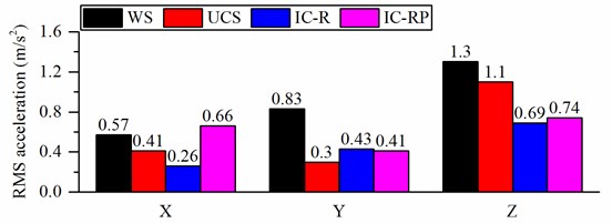
a) RMS acceleration when the forward speed is 6 m/s
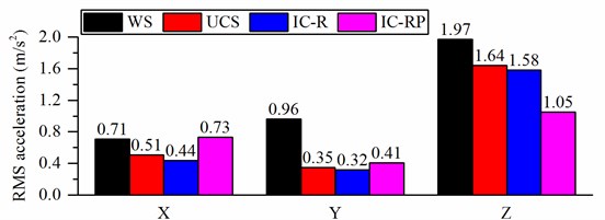
b) RMS acceleration when the forward speed is 11 m/s
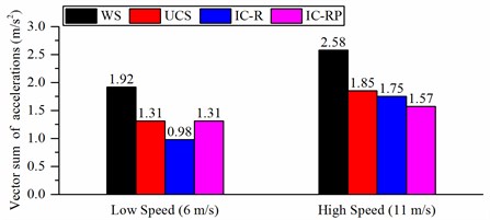
c) Vector sum of the weighted accelerations
5.2. Responses to stability in turning maneuvers
Fig. 13 illustrates the roll angle and LTR of the wheel loader when it turns on a flat road. For the wheel loader without suspension, the changes of the roll angle of the vehicle frame are unnoticeable when turning at different forward speeds. The roll angle increases from 0.25° to 0.35° when the speed increases from 5 m/s to 7 m/s. This slight change will not be felt by the driver in actual driving. For the wheel loader with suspension, the roll angle increases significantly as the speed increases during turning, the roll angle increases from 0.75° to 1.4° for IC-R strut and from 0.7° to 1.3° for IC-RP strut. This increase in roll angle will give the driver a sense of psychological fear, which will affect safe driving. An increase in the roll angle will be greater if the hydropneumatic suspension is not applied with the interconnection type with an anti-roll capability, as shown in Fig. 13(b), the roll angle of the wheel loader with UC strut is more than 10°, which can cause the vehicle to lose stability.
According to Figs. 13(c) and (d), it can be found that the suspensions of IC-R and IC-RP struts have little effect on the LTR and do not increase the risk of vehicle instability, whereas the UCS suspension can affect the steering stability.
Fig. 13Response of the wheel loader with different suspension struts when turning on the flat road
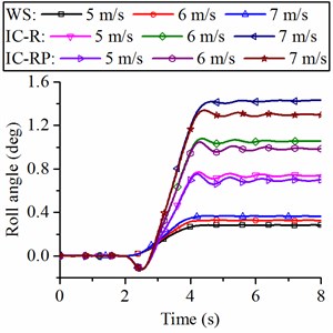
a) Roll angle of the loader with different suspension struts (WS, IC-R and IC-RP)
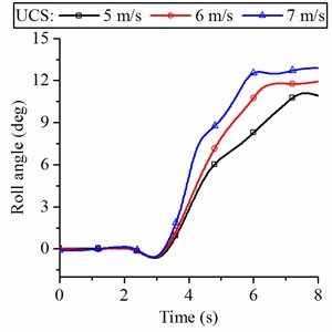
b) Roll angle of the loader with UCS
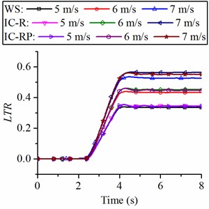
c) LTR of the loader with different suspension struts (WS, IC-R and IC-RP)
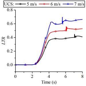
d) LTR of the loader with UCS
5.3. Analysis of the influence of the suspension system on operation performance
Figs. 14(a) and (b) show the pitch angle of the vehicle body, and the vertical displacement of the bucket during the scooping and unloading processes. At the 0 s to 4 s stage, the loader travels toward the pile at a speed of 1 m/s. The pitch angle of the vehicle body is kept at zero. The vertical position of the bucket is −430 mm, which corresponds to the coordinate o-xyz, as shown in Fig. 10.
At the 7 s to 10 s stage, the bucket and lift cylinders begin to protrude, and the bucket moves upward to excavate the material. The suspensions of UCS and IC-R struts greatly influence the pitch angle of the vehicle at this stage Fig. 14(a). However, the pitch angle slightly changes during excavation when the wheel loader has IC-RP suspension, this change is mainly due to the IC-RP form that has a good anti-pitching ability. In addition, the IC-RP suspension has little effect on the vertical displacement of the bucket, as shown in Fig. 14(b), but the suspensions of UCS and IC-R struts largely effect on the vertical displacement of the bucket at this stage. The vertical height of the bucket reaches 760 mm when the loader with IC-RP suspension or without suspension. For the wheel loader with UCS and IC-R suspensions, the bucket height only reaches 670 mm when excavating crushed rocks. The changes in the pitch angle and vertical displacement of the bucket seriously affect the digging performance of the loader, especially in terms of excavation force, excavation efficiency, and full bucket ratio. Furthermore, a large pitch angle can make the driver feel uncomfortable and affect the driver’s operating accuracy.
During the unloading phase (from 18 s to 21 s), the bucket can be raised to 1200 mm when the wheel loader with IC-RP suspension or without suspension, whereas the bucket can only be raised to 1100 mm with UCS and IC-R suspensions. Hence, the suspension also affects the accuracy of the unloading process. In this case, decreasing the height of the bucket lift may cause the bucket to bump into the truck when the loader unloads the material onto the truck.
Fig. 14Responses of the wheel loader with different suspension struts when scooping and unloading crushed rocks
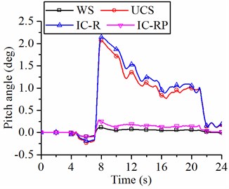
a) Pitch angle
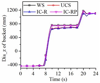
b) Vertical displacement of the bucket
6. Future work
This suspension model aims to investigate the basic effects of adding an axle suspension on the wheel loader; hence, optimization is not performed in terms of the detailed suspension geometry and kinematics. Future works should thus investigate the effects of detailed suspension dimensions and strive to optimize the geometry although a higher modeling fidelity would be required.
7. Conclusions
This study aimed to analyze the effects of hydropneumatic suspension with different struts on the ride comfort, driving stability and operational stability of a wheel loader. Multibody models of a wheel loader with hydropneumatic suspensions have been developed, evaluated, and compared with a traditional wheel loader without suspension. Detailed analysis was conducted under the conditions of traveling on a C-class road, turning on a flat road, and scooping and unloading crushed rocks. The following are the analysis results:
1) The three suspensions with different forms can significantly reduce the vector sum of the weighted accelerations. Under the low speed (6 m/s) condition, the IC-R and IC-RP suspensions can reduce vibration by 49 % and 32 %, respectively. The IC-RP suspension can reduce the total vibration by 39 % under the high speed (11 m/s) condition.
2) Although the IC-R and IC-RP suspensions have anti-roll function, the roll angle of the vehicle reaches 1.3° when the wheel loader turning at the speed of 7 m/s, which may trigger the driver’s fear psychologically, but they do not affect the LTR value when the wheel loader turns on the flat road with different speeds. The UCS suspension without anti-roll function cannot guarantee the steering stability.
3) The IC-RP suspension has little effect on the pitch angle of the vehicle and the vertical displacement of the bucket when the wheel loader is scooping and unloading crushed rocks. However, the wheel loader with UCS and IC-R has a large pitch angle, and the bucket vertical displacement cannot reach the predetermined height during scooping and unloading, which will affect the excavation performance and the driver’s operational accuracy.
IC-RP suspension with anti-roll and anti-pitch functions improves ride comfort while ensuring driving and operation stability of the wheel loader considering vibration reduction, driving stability, and operation stability.
References
-
Zhao X., Michael K., Christian S. Assessment of wheel loader vibration on the riding comfort according to ISO standards. Vehicle System Dynamics, Vol. 51, Issue 10, 2013, p. 1548-1567.
-
Zhao X., Schindler C. Evaluation of whole-body vibration exposure experienced by operators of a compact wheel loader according to ISO 2631-1:1997 and ISO 2631-5:2004. International Journal of Industrial Ergonomics, Vol. 44, Issue 6, 2014, p. 840-850.
-
Cation S., Jack R., Oliver M. Six degree of freedom whole-body vibration during forestry skidder operations. International Journal of Industrial Ergonomics, Vol. 38, Issue 9, 2008, p. 739-757.
-
Ahmadian M. Editors’ perspectives: road vehicle suspension design, dynamics, and control. Vehicle System Dynamics, Vol. 49, Issue 1, 2011, p. 3-28.
-
Pazooki A. Ride and Directional Dynamic Analysis of Articulated Frame Steer Vehicles. Ph.D. Thesis, Concordia University, 2012.
-
Rehnberg A., Drugge L. Ride comfort simulation of a wheel loader with suspended axles. International Journal of Vehicle Systems Modelling and Testing, Vol. 3, Issue 3, 2008, p. 168-188.
-
Pazooki A., Cao D., Rakheja S. Ride dynamic evaluations and design optimisation of a torsio-elastic off-road vehicle suspension. Vehicle System Dynamics, Vol. 49, Issue 9, 2011, p. 1455-1476.
-
Rehnberg A., Drugge L., Trigell A. S. Snaking stability of articulated frame steer vehicles with axle suspension. International Journal of Heavy Vehicle Systems, Vol. 17, Issue 2, 2010, p. 119-138.
-
Yao Z., Wang G., Li X., et al. Dynamic simulation for the rollover stability performances of articulated vehicles. Proceedings of the Institution of Mechanical Engineers, Part D: Journal of Automobile Engineering, Vol. 228, Issue 7, 2014, p. 771-783.
-
Pacejka H. B. Tire and Vehicle Dynamics. Society of Automotive Engineers Inc., Oxford, 2002.
-
Li X., Wu Y., Zhou W., Yao Z. Study on roll instability mechanism and stability index of articulated steering vehicles. Mathematical Problems in Engineering, Vol. 2016, 2016, p. 1-15.
-
Coetzee C. J., Els D. N., Dymond G. F. Discrete element parameter calibration and the modelling of dragline bucket filling. Journal of Terramechanics, Vol. 47, Issue 1, 2010, p. 33-44.
-
Bauer W. Hydropneumatic Suspension Systems. Springer Berlin Heidelberg, 2011.
-
Chaudhary S. Ride and Roll Performance Analysis of a Vehicle with Spring Loaded Interconnected Hydropneumatic Suspension. Ph.D. Thesis, Concordia University, 1998.
-
Mechanical Vibration – Road Surface Profiles – Reporting of Measured Data. International Standards Organization, ISO 8608, 1995.
-
Cao J., Liu H., Li P. State of the art in vehicle active suspension adaptive control systems based on intelligent methodologies. IEEE Transactions on Intelligent Transportation Systems, Vol. 9, Issue 3, 2008, p. 392-405.
-
Yu F., Zhang J. W., Crolla D. A. A study of a Kalman filter active vehicle suspension system using correlation of front and rear wheel road inputs. Proceedings of the Institution of Mechanical Engineers, Part D: Journal of Automobile Engineering, Vol. 214, Issue 5, 2000, p. 493-502.
-
Mechanical Vibration and Shock – Evaluation of Human Exposure to Whole-Body Vibration. Part 1 – General Requirements. International Standards Organization, ISO 2631-1, 1997.
-
Yoon J., Kim D., Yi K. Design of a rollover index-based vehicle stability control scheme. Vehicle System Dynamics, Vol. 45, Issue 5, 2007, p. 459-475.
Cited by
About this article
This study was supported by the National Natural Science Foundation of China (Grant No. 51505177), Science and Technology Development Program of Jilin Province (Grant No. 20160520073JH) and Postdoctoral Science Foundation of China (Grant No. 163808).

