Abstract
The test rig of gas bearing-rotor system was established. The rotor was composed of turbine, compressor and four disks, it was supported by hydrostatic gas bearings. With this test rig, the dynamics of rotor bearing system with different bearing radial clearances were researched. Rotating speed of shaft could be higher with large bearing clearance, but speed soaring and low frequency oscillation occurred were dangerous to the shaft; with small bearing clearance, the speed soaring and low frequency oscillation could be eliminated and the dynamic characteristic was good, but rubbing deceleration was more likely to happen. Make a contrast of the dynamics with different radial clearances, it could be found that the dynamic characteristic of small radial clearance was good, but the threshold of safe amplitude was small, which limited the maximum speed.
1. Introduction
Because of the high speed, low viscosity, low friction power, long life of gas bearing, it has a unique advantage in the high-speed micro-power fields. But owing to the low damping and low carrying capacity, gas-bearing has poor dynamics and stability. Whirl, oscillation and malfunctions may occur in rotors supported by gas bearings [1]. The stability and fault characteristics of high-speed rotating machines supported by gas bearings were widely researched.
In 1965, linear bearing stiffness and damping coefficients were put forward by Lund, the film stability theory was established [2]. In 1966, low frequency vibration was observed by Enrich in experiments, the chaos of high-speed rotor-bearing system was elaborated [3]. The numerical analysis and experimental research of rigid rotor supported by compound bearings were done by Yuta Otsu, it could be found that the instability threshold of the bearing with compound restrictors is higher than the conventional bearings [4]. The stability of rotors supported by hydrostatic bearing compensated by orifices and inherences were compared by Cheng-Hsien Chen, it revealed that the load of bearing compensated by orifices was higher but the damping of it was smaller [5]. An air pressure regulator was employed by Luis San Andrés to control the supply pressure of the bearings, which was useful to reduce or eliminate high amplitudes of rotor motion while crossing the system critical speed [6]. The methods to enhance stability were carried out extensive research. Different methods such as tangential gas supply method, bearing with elastic supports, bearing stiffness anisotropy method were put forward to increase the stability of gas bearing [7]. Flow field calculation of hydrostatic gas bearing, dynamic and static characteristics analysis, coupling calculation and experiments of gas bearing rotor system were carried out by Zhao Guang, in order to improve the stability of high speed gas bearing-rotor system [8].
Designing of supply holes, supporting pattern of bearing, gas supply pressure and so on were carried out extensive research, but the influence of radial clearance on gas bearing wasn’t researched widely. The four disks turbine compressor rotor supported by gas bearing was established. Based on it, the influence of radial clearance on rotor dynamic was researched, some achievements were obtained.
2. Test facility
Rotor-bearing system, data acquisition and analysis system, gas pipeline and control system, and load system were included in the test system. The system was shown in Fig. 1.
The rotor-bearing system was made up of turbine, compressor, four disks and so on. Hydrostatic radial thrust gas bearings were used and placed according to the thrust plates. Parameters of the system were listed in Table 1.
Eddy current sensors were used in data acquisition and analysis system to monitor vibration. Both sides of compressor and turbine were placed sensors to monitor the vertical, horizontal vibration and rotating speed. Gas pipeline and control system could provide high-pressure gas for gas bearings and driving gas for rotating. Load system could achieve load output.
Fig. 1Test equipment and system
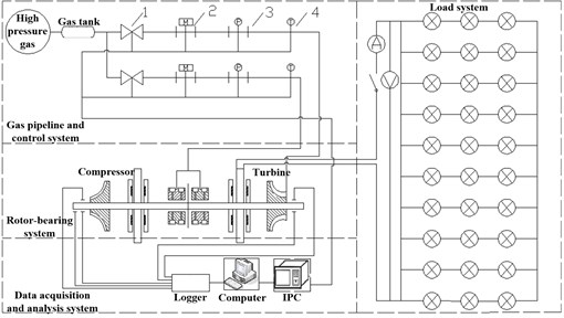
Table 1Parameters of rotor-bearing system
Geometric parameters | Symbol/Unit | Numerical |
Bearing width | L / mm | 36 |
Bearing inner diameter | D / mm | 25 |
Number of radial stomata for bearing | n / 1 | 16 |
Rows of radial stomata for bearing | N / 1 | 2 |
Length of rotor | L / mm | 300 |
Rotor span | Ln / mm | 41 |
Disk diameter | mm | 88 |
Disk thickness | mm | 6 |
3. Experimental phenomena and analysis
3.1. Experimental program
Stability experiments of rotor-bearing system with different radial clearances were designed. Experimental program was listed in Table 2. Supply pressure of bearings are all about 0.7 MPa, and rotor powered by turbine. The only changing parameter was radial clearance.
Table 2Experimental program
Test number | Driving mode | Gas supply pressure of bearing (MPa) | Radial clearance (mm) | ||
Turbine | Compressor | Turbine | Compressor | ||
1 | Turbine drive | 0.697 | 0.695 | 0.0500 | 0.0400 |
2 | 0.690 | 0.700 | 0.0400 | 0.0250 | |
3 | 0.695 | 0.690 | 0.0250 | 0.0400 | |
4 | 0.650 | 0.650 | 0.0075 | 0.0175 | |
5 | 0.680 | 0.670 | 0.0025 | 0.0125 | |
First the dynamic of rotor-bearing system with clearances of 0.0500 mm and 0.0400 mm (turbine and compressor) was tested in test one. In test two, clearances of turbine and compressor were decreased to 0.0400 mm and 0.0250 mm and the stability of system was researched. Clearances of rotor-bearing were continually decreased and test three to five were conducted. The results would be illustrated below.
3.2. Experimental phenomenon
Three-dimensional spectrum of test one was shown in Fig. 2. The abscissa of spectrum is frequency, ordinate is time and color of the picture represents the amplitude of vibration. The maximum speed of test one was 47500 rpm and the speed decreased to 0 rpm at maximum speed owing to rubbing. It was difficult to manually rotate the rotor after the speed decreased to 0 rpm.
Critical speed of test one was 7520 rpm. After critical speed, the speed soaring occurred at point A and reached 12115 rpm. At point B, the violent speed soaring occurred. Between A and B, namely section one, rich frequency components appeared.
Fig. 2Three-dimensional spectrum of test one
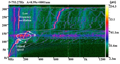
Fig. 3Spectrogram of section one
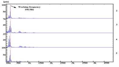
Fig. 4Bifurcation of section one
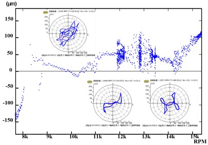
Fig. 5Bifurcation of low frequency oscillation
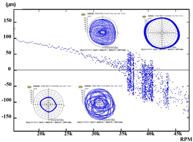
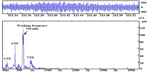
Spectrogram of section one was depicted in Fig. 3. The working frequency was 198.5 Hz, and the harmonic components such as 3/4X, 1/2X, 6/5X and 10/3X were contained in section one, clipping occurred in time domain signal. It could be concluded that rubbing happened in section A. Bifurcation diagram of section one was shown in Fig. 4. With the bifurcation entered into chaos, the amplitude increased suddenly, and decreased until quit. The orbits were complex and multi-periods.
At point B, speed soared from 15288 rpm to 36202 rpm, speed increasing rate was 1209.3 rpm/s. The low frequency oscillation occurred at 36202 rpm and the frequency was 134.6 Hz. With the increasing of speed, the gas film stiffness increased, which led to the frequency of oscillation was higher than the critical speed. In Fig. 5 the orbits entered into chaos from period one when the low frequency occurred. After exiting oscillation, the orbits back to period one, the amplitude of vibration increased to 160 μm.
Decreasing radial clearance, test two and three were conducted. The three dimensional spectrum of test two was in Fig. 6. The characteristic of test three was similar with two, so the spectrum wasn’t depicted.
At test two, the maximum speed was 42498 rpm, and the rubbing deceleration happened at maximum speed. It could be found that frequency of oscillation was 105.4 Hz and occurred at speed 30147 rpm. The maximum speed was 41176 rpm, and the rubbing deceleration appeared at test three. The oscillation still existed and frequency was 112.7 Hz, occurred at speed 21030 rpm.
Concluding the phenomenon above, it revealed that with decreasing clearances, the speed soar and section one in test one disappeared. But the low frequency oscillation didn’t change much. Experiments with smaller clearances were conducted to research the dynamic characteristics.
Three dimensional spectrum of test four was depicted in Fig. 7. The critical speed of test four was 11819 rpm and maximum speed was 31985 rpm. It could be concluded that through Fig. 7 only working frequency existed and the speed soaring and oscillation disappeared. At the maximum speed, the rubbing deceleration occurred, but the rotor didn’t locked. Critical speed of test five was 10540 rpm and the maximum speed was 27909 rpm. The speed soaring and oscillation disappeared but the rotor locking still existed.
Fig. 6Three dimensional spectrum of test two
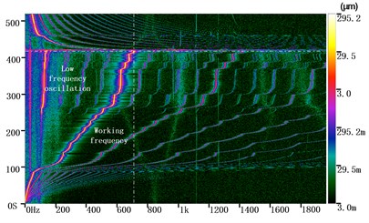
Fig. 7Three dimensional spectrum of test four
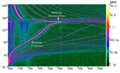
Fig. 8Compare of the characteristics
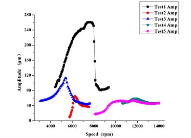
a) Critical speeds
b) Spectral characteristics
3.3. Comparison of spectral
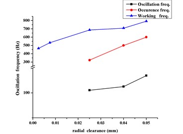
The characteristics of critical speeds were shown as Fig. 8. The critical speed amplitude of test one was big, this led to energy accumulation when pass through critical speed, the speed soaring at point A occurred because of the energy release after critical. When the amount of unbalanced mass decreased, the speed soaring after critical speed vanished. What’s more, it could be concluded that with decreasing clearance, the critical speed increased, but critical speeds of test two and three showed opposite trend, future research was needed to explain this phenomenon.
Compare with spectral characteristics of different radial clearances, the low frequency oscillations occurred when the clearance was big, working frequency when the oscillation occurred, frequency of oscillation and stability threshold all decreased with clearance decreasing. When the clearance was small, the rubbing deceleration was easily to happen. It could be concluded that there was an optimal clearance, which could lead to higher stability threshold and avoid the occurrence of oscillation. The optimal clearance would be researched in the future.
Fig. 9Dynamic at deceleration of test one
a) Orbits
b) Spectrum
Fig. 10Dynamic at deceleration of test five
a) Orbits
b) Spectrum
3.4. Vibration characteristics at deceleration point
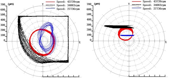
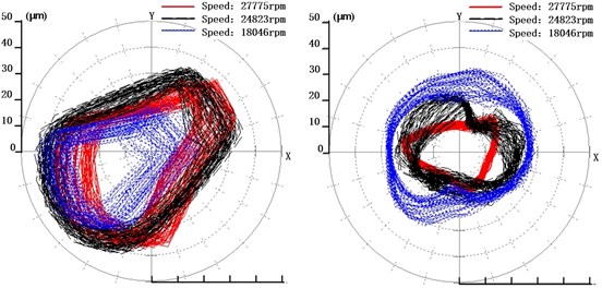
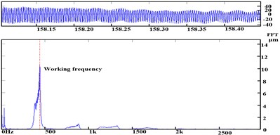
In the orbits of Fig. 9 and 10, different colors represented different time. The red orbits were before rubbing, the black was during rubbing and the blue was after rubbing. What’s more, the left was the orbit of turbine side and the right was the compressor side.
The red orbit in the test one was in period one and the amplitude was small. During the rubbing, the amplitude increased beyond the range of the sensors and the orbits was trimmed. After rubbing, the orbits back into period one and amplitude decreased. During the rubbing deceleration, motion in vertical direction was constrained and the orbit was a line in the compressor side. This indicated that the rotor close to the bearing wall, serious rubbing happened during the deceleration.
During the rubbing deceleration, test two and three both appeared vibration instability. The amplitude of orbits increased beyond the range of sensors, and the orbits were trimmed as test one. At test four the increasing of amplitude could still be observed but it didn’t beyond the limit of sensors. The orbits of them were all similar with test one, so they weren’t listed here. Amplitude of test five didn’t change too much and the orbits still in period one. Test one to there all had harmonic components, this indicated that instability of dynamic was the major reason to result in rubbing deceleration. Test four and five only working frequency existed and the amplitude was small, this indicated that owing to clearance decrease system couldn’t endure the amplitude, stability threshold decreased.
4. Conclusions
This paper established the rotor-gas bearing system and researched the dynamics of rotor-bearing system with different radial clearances. The conclusions were listed as follows:
With decreasing of bearing radial clearance, the speed soaring and low frequency oscillation during speed up vanished. This indicated that small radial clearance was beneficial to stability of rotor-bearing system.
The stability threshold decreased at small radial clearance, the rubbing deceleration occurred when the amplitude was small. When the clearance was big, the instability of dynamics led to rubbing, but when the clearance was small, it is the small clearance that couldn’t endure the amplitude of working frequency. There is an optimal clearance which can eliminate oscillation and lead to a higher maximum speed.
Reducing imbalance mass is useful to limit the speed soaring occurred when pass through critical speed, the energy accumulation is small owing to small amplitude.
References
-
Hamrock B. J. Fundamentals of Fluid Film Lubrication. McGraw-Hill, New York, 1994.
-
Lund Jorgen W. The stability of an elastic rotor in journal bearings with flexible, damped supports. Journal of Applied Mechanics, Vol. 32, Issue 4, 1965, p. 911-920.
-
Ehrich F. E. Sub-harmonic vibration of rotors in bearing clearance. ASME Paper No. 66-MD-1, 1966.
-
Yuta Otsu, Kei Somaya, Shigeka Yoshimoto High speed stability of a rigid rotor support by aerostatic journal bearings with compound restrictors. Tribology International, Vol. 44, Issue 1, 2011, p. 9 17.
-
Chen C.-H., Tsai T.-H., et al. The comparison in stability of rotor-aerostatic bearing system compensated by orifices and inherences. Tribology International, Vol. 43, Issue 8, 2010, p. 1360 1373.
-
Luis San Andrés, Keun Ryu Hybrid gas bearings with controlled supply pressure to eliminate rotor vibrations while crossing system critical speeds. Journal of Engineering for Gas Turbines and Power, Vol. 130, Issue 6, 2008, p. 062505.
-
Ma Wenqi, Yu Hechun, Sun Ang Research situation of gas-bearing rotor system. Lubrication Engineering, Vol. 35, Issue 6, 2010, p. 121-125.
-
Zhao Guang, Liu Pannian, et al. Research on gas film force of aerostatic gas bearing and its coupled dynamics with rotor. Journal of Aerospace Power, Vol. 27, Issue 2, 2012, p. 472-480.
-
Han Dongjiang, Yang Jinfu Experimental research on the dynamic characteristics of gas bearing-flexible rotor system. Journal of Vibroengineering, Vol. 16, Issue 5, 2014, p. 2363-2374.
