Abstract
In order to decrease the power consumption of current piezoelectric stack actuator for incus-body driving type middle ear implant (MEI), a new MEI’s piezoelectric actuator with a flextensional amplifier was proposed. To aid the design process of this actuator, a human middle-ear mechanical model, which incorporated the viscoelastic properties of middle ear soft tissues, was established using finite element method. And the validation of this model was confirmed by comparing the model-predicted results with temporal bone experimental data. Then, based on this model, a coupling mechanical model of the flextensional piezoelectric actuator and the human ear was constructed and used to study the equivalent sound pressure level and power consumption of the actuator. The results show that the hearing compensation performance of the piezoelectric actuator was improved by introducing the flextensional amplifier, and the power consumption of the actuator was reduced significantly.
1. Introduction
Hearing loss is one of the most common diseases worldwide. Besides, due to the increase in aging population, the number of people affected by hearing loss is still steadily increasing. Thus, it is more important than ever to treat hearing loss. There are two main types of hearing loss: the conductive hearing loss and the sensorineural hearing loss. With the continuous enrichment of audiology theory and the rapid development of ear surgery, the majority of patients with conductive hearing loss can improve the hearing through operation. But there is still lack of effective treatment for patients with sensorineural hearing loss, most of these patients can only use conventional hearing aids to improve hearing [1]. However, traditional hearing aids have some inherent deficiencies, such as ear canal occlusion, limited amplification, sound distortion, discomfort, and acoustic feedback [2]. To solve these problems, many institutions began to investigate the middle ear implants (MEIs), which compensate hearing loss by their implanted actuators’ mechanical vibration [3].
From 1990, some types MEIs been investigated or developed in the world. According to the different stimulating positions of their actuators, MEIs can mainly be divided into three types: the incus-body driving [4-6], the round-window driving [7-9] and the incus-long-process driving [10-12]. Among them, as the incus-body driving type MEI, which has its actuator attached to the incus body, is one of the widely investigated types due to its minor damage to the structure of the human middle ear system. So far, this type of MEI consists of an electromagnetic actuator or a piezoelectric diaphragm actuator. Compared with the electromagnetic actuator, the piezoelectric diaphragm actuator has demonstrated many advantages including wider bandwidth, ease of fabrication, more compatible with external magnetic environment and lower power consumption. Nevertheless, due to its specific structure, the piezoelectric diaphragm actuator cannot generate enough output at high frequencies [13]. This property makes the piezoelectric MEI cannot compensate severe sensorineural hearing loss efficiently, since this type of hearing loss usually severe at high frequencies [1]. In order to overcome the shortcoming of the piezoelectric diaphragm actuator, Wang et al. [13] proposed a novel incus-body driving type MEI which used a piezoelectric stack to fabricate its actuator. And their temporal bone experimental results show that the piezoelectric stack actuator does have a better hearing loss compensation performance at high frequencies. However, the power consumption of this novel piezoelectric actuator is relatively large, which can’t meet the portable requirement of the MEI.
Accordingly, to reduce the power consumption of the piezoelectric stack actuator for the incus-body driving type MEI, a new flextensional piezoelectric actuator was proposed in this paper. Based on human ear anatomic structure and a constructed mechanical model, the main parameters of the actuator were ascertained to generate sufficient excitation force for patients with severe sensorineural hearing loss. The results show the new MEI’s piezoelectric actuator not only maintains the advantages of higher output gain at high frequencies, but also greatly reduces the power consumption.
2. Structure of the flextensional piezoelectric actuator
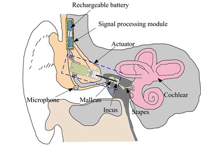
The overall schematic of the incus-body driving type MEI is shown in Fig. 1. The MEI mainly consists of a microphone for receiving an acoustic signal from outside, a signal processing module for receiving the signal from the microphone and generating a corresponding electric signal, an actuator for outputting a vibration to the incus body in response to the electrical driving signal from the signal processing module, and a rechargeable battery for supplying the power to the whole system.
Fig. 1Schematic of the middle ear implant
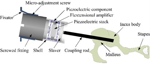
The actuator is the most important component of the MEI, since it provides a direct mechanical stimulation to the ossicular chain. Fig. 2 shows the structure of our proposed flextensional piezoelectric actuator, which mainly includes a fixator, a screwed fitting, a micro-adjustment screw, a piezoelectric component, a salver, a shell and a coupling rod. And the piezoelectric component is composed of a flextensional amplifier and a piezoelectric stack. During the surgery, this actuator is implanted into the body of the mastoid chamber. And the fixator part is fixed on the skull by the bone nail, and supports the whole actuator. One side of the screwed fitting is fixedly connected with the base of the piezoelectric component, the other side is connected to the fixator. The salver is settled in the shell and is fixedly connected with the base part of the coupling rod. The geometry of the salver walls is consistent with the inner wall of the shell of the piezoelectric component, thereby forming a sliding pair, which makes the output displacement direction of the coupling rod coincide with the one of the piezoelectric component. One end of the coupling rod is linked by the salver, the other end is attached to the incus body.
The piezoelectric component is the key part in the whole mechanical structure of the actuator; therefore, it is mainly designed in this paper. As mentioned before, the piezoelectric component is mainly composed of a piezoelectric stack, which is placed in the flextensional amplifier as shown in Fig. 2. Under the action of a driving voltage, the piezoelectric stack can do telescopic motion, and the motion is boosted by the flextensional amplifer and transmitted to the incus body by the coupling rod, which will drive the movement of the ossicular chain to compensate hearing loss.
Fig. 2Configuration of the flextensional piezoelectric actuator
3. Design parameters
3.1. Dimensions of the fextensional piezoelectric actuator
The fextensional piezoelectric actuator is surgically implanted into the mastoid region of the temporal bone. Because of the limited space for human temporal bone mastoid, the dimensions of the actuator should be restricted. However, small dimensions will increase the requirements for manufacturing process. Considering above two factors, the cross-sectional area of the piezoelectric stack is set to 1 mm2 (1 mm×1 mm) with a total height of 2 mm. And the material of this piezoelectric stack is selected as lead zirconate titanate (PZT-4) ceramics considering its common use and low cost. To further reduce the power consumption of the piezoelectric stack actuator, a flextensional amplifier is introduced into the actuator, as shown in Fig. 3. When the piezoelectric stack produces a delta x deformation under a driving voltage, the flextensional amplifier will produce a delta y displacement. The relationship between these two displacements is shown in Eq. (1). G is the gain of the displacement magnification, and its value can be derived from Eq. (2) [14]:
where L is the cavity length of the flextensional amplifier, h is the unilateral inner concave depth of the flextensional amplifier. Considering the restriction of temporal bone mastoid in the implant position, L and h are set to 2.6 mm and 0.2 mm, respectively. Thus, the value of G is calculated to be 6.5.
Fig. 3Schematic diagram of the flextensional piezoelectric actuator
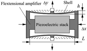
a) Contraction
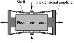
b) Extension
Considering the biocompatibility, titanium alloy was selected as the material of the flextensional amplifier. It had a density of 4430 kg/m3, a Young’s modulus of 116 GPa, and a Poisson’s ratio of 0.32. The outer dimensions of the flextensional amplifier structure were 3 mm in length, 1mm in width and 1.6 mm in height. And the shell wall thickness of the flextensional amplifier was 0.05 mm. The total mass of the piezoelectric component was 20.8 mg.
3.2. The piezoelectric stack’ layer number of the actuator
The piezoelectric stack’ layer number is a key parameter of the piezoelectric actuator, since it determines the output displacement of the actuator under a certain driving voltage. However, as the middle ear system has complicated geometry and extremely small structure, it is difficult to study the layer number’s influence on the actuator’s hearing compensation performance by human temporal bone experiment. Therefore, a human middle-ear biomechanics model must be established to aid this study. Considering the finite element method (FEM) has the advantage of handling complex geometries [15, 16], a finite element human middle ear was established firstly. Then, the layer number of the piezoelectric stack was ascertained based on this model.
3.2.1. The FE model of the middle ear
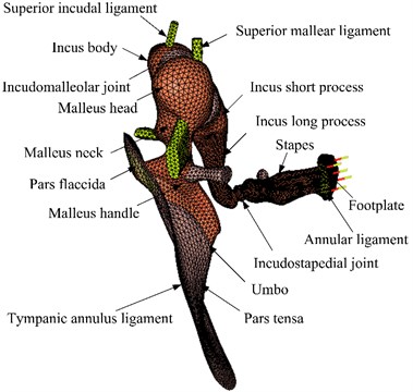
A human middle ear FE model, which was mainly based on our earlier model [17], was constructed as shown in Fig. 4. The Poisson’s ratio of all components of the middle ear was assumed to be 0.3, Young’s modulus and the densities were estimated from the literature reports [18-22] and were listed in Tables 1 and 2. In addition, recent experimental results show that some tissues of the middle ear have viscoelastic material properties, such as tympanic membrane and middle ear soft tissue. Therefore, the viscoelastic properties of the middle ear soft tissues [23] were incorporated into the model. Rayleigh damping parameters were defined to the other components in the middle ear, the damping coefficients were set as α= 0 s-1, β= 7.5×10⁻⁵ s.
Fig. 4The human middle ear finite element model
The relaxation modulus of the middle ear soft tissues can be expressed as Prony series [24]. In this paper, the first order Prony series is used to simulate the viscoelastic properties of human ear soft tissue as shown in Eq. (3) [25]:
where E0 is the Young’s modulus, E1 and τ1 are the viscoelastic material parameters and listed in Table 3, t is the time.
Table 1Material properties of human middle ear components
Components | Our model | Data from literatures |
Eardrum | ||
Density (kg/m3) | 1.2×10³ | 1.2×10³ [18] |
Young’s modulus (N/m2) | ||
Pars tensa | 1.0×10⁷ | 1×10⁷ [18] |
Pars flaccida | 1.0×10⁷ | 1×10⁷ [18] |
Malleus | ||
Density (kg/m3) | ||
Head | 2.55×10³ | 2.55×10³ [19] |
Handle | 3.70×10³ | 3.7×10³ [19] |
Neck | 4.53×10³ | 4.53×10³ [19] |
Young’s modulus (N/m2) | 1.41×10¹⁰ | 1.41×10¹⁰ [20] |
Incus | ||
Density (kg/m3) | ||
Body | 2.36×10³ | 2.36×10³ [19] |
Short process | 2.26×10³ | 2.26×10³ [19] |
Long process | 5.08×10³ | 5.08×10³ [19] |
Young’s modulus (N/m2) | 1.41×10¹⁰ | 1.41×10¹⁰ [20] |
Stapes | ||
Density (kg/m3) | 2.20×10³ | 2.20×10³ [19] |
Young’s modulus (N/m2) | 1.41×10¹⁰ | 1.41×10¹⁰ [20] |
Incudomalleoular joint | ||
Density (kg/m3) | 3.20×10³ | 3.20×10³ [21] |
Young’s modulus (N/m2) | 1.41×10¹⁰ | 1.41×10¹⁰ [21] |
Incudostapedial joint | ||
Density (kg/m3) | 1.20×10³ | 1.20×10³ [21] |
Young’s modulus (N/m2) | 6.00×10⁵ | 6.00×10⁵ [21] |
Manubrium | ||
Density (kg/m3) | 1.00×10³ | 1.00×10³ [21] |
Young’s modulus (N/m2) | 4.70×10⁹ | 4.70×10⁹ [21] |
Table 2Young’s modulus for ligament and muscle components
Components | Young’s modulus (N/m2) | |
Our model | Data from literatures | |
Tympanic annular ligament | 6.0×10⁵ | 6.0×10⁵ [21] |
Lateral mallear ligament | 1.0×10⁵ | 1.0×10⁵ [22] |
Superior mallear ligament | 5.0×10⁶ | 4.9×10⁶ [21] |
Superior incus ligament | 5.0×10⁶ | 4.9×10⁶ [21] |
Anterior mallear ligament | 2.0×10⁶ | 2.1×10⁶ [22] |
Posterior incudal ligament | 6.5×10⁶ | 6.5×10⁶ [21] |
Tensor tympani tendon | 7.0×10⁷ | 7.0×10⁷ [21] |
Stapedial annular ligament | 1.0×10⁵ | 2.0×10⁵ [21] |
Stapedial tendon | 5.2×10⁷ | 5.2×10⁷ [21] |
Table 3The viscoelastic parameters of soft tissues in the human middle ear FE model
Components | E1 | τ1 (μs) |
Tympanic membrane, pars flaccida | 2.29 | 25 |
Tympanic membrane, pars tensa | 5.56 | 25 |
Incudomalleolar joint | 6 | 20 |
Incudostapedial joint | 5.67 | 20 |
Stapedial annular ligament | 13.29 | 24 |
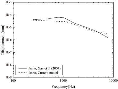
To evaluate our improved middle-ear FE model, experimental data of stapes and umbo displacements obtained from 10 human temporal bones by Gan et al. [26] were utilized for the comparison. They delivered 10 pure-tone sounds of 90 dB SPL near the eardrum in their experiment, and measured the corresponding displacements of the stapes and the umbo using a laser Doppler vibrometer. For validation, we applied the same sound pressure (90 dB SPL) on the lateral side of the eardrum in our middle-ear FE model, and calculated the displacements of the stapes and the umbo across the frequency range of 250-8000 Hz as shown in Fig. 5 and Fig. 6.
Fig. 5 indicates that, comparing with our previous model, the current middle-ear FE model incorporating the viscoelastic properties does improve the model-predicted stapes displacement, especially at higher frequencies. This is attributable to the fact that the Rayleigh damping, which was only used in our previous model, makes the damping of the soft tissues in the middle-ear FE model proportional to the frequency as well as too high at the higher frequencies [27]. Besides, the comparisons in Fig. 5 and Fig. 6 show that our model-predicted results were very consistent with the experimental data. Thus, our constructed human middle ear FE model can be used to assist the design of the MEI.
Fig. 5Comparison of the displacements at the stapes footplate
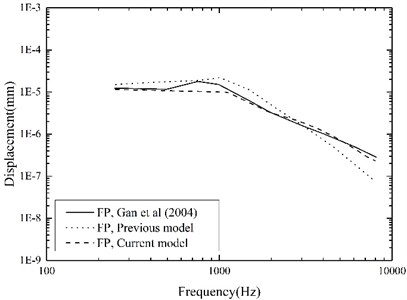
Fig. 6Comparison of the displacements at the umbo
3.2.2. Coupling mechanical model of the human middle ear and the piezoelectric actuator
In order to establish the coupling mechanical model, a FE model of piezoelectric actuator was constructed firstly. The material properties of the piezoelectric stack were listed in Table 4, its polarization direction was the telescopic motion direction of the piezoelectric actuator. The piezoelectric FE model equations can be expressed by Eq. (4) [28, 29]:
where U is nodal displacement, φ is nodal electrical potential, F is the mechanical efforts and Q is the nodal electric loads.
The above equations can also be transformed into the following matrix:
where:
where is mechanical stiffness matrix, is the piezoelectric coupling matrix, is dielectric stiffness matrix, is mass matrix, is mechanical damping matrix, and is derivatives of FE model shape function, and is damping coefficient.
Table 4Material parameters of the PZT-4
Elastic stiffnesses (GPa) | Piezoelectric coefficients (C/m2) | Dielectric constants (×10-10C/V m) | Density (kg/m3) | ||||||||
139 | 77.8 | 74.3 | 115 | 25.6 | 30.6 | 12.7 | –5.2 | 15.1 | 64.6 | 56.2 | 7500 |
Then the flextensional amplifier was introduced into the piezoelectric actuator, and the coupling mechanical model of the human middle ear and flextensional piezoelectric actuator was constructed, as shown in Fig. 7. The flextensional piezoelectric actuator is mainly composed of a screwed fitting, a flextensional amplifier, a piezoelectric stack, a slaver, and a coupling rod. Each components’ function has been described in section 2. And the dimension parameters of the flextensional piezoelectric actuator are listed in Table 5. Since the actuator is implanted in the mastoid cavity, the anatomical dimensions of human temporal bone were also considered during the design of the maximum diameter and the total length of the actuator. Based on 50 human temporal bones’ evaluation, Maassen et al. proved that an 8.5 mm diameter actuator can be implanted in the mastoid cavity [30]. And the maximum diameter of our actuator is 4.5 mm, which is less than the value of Maassen et al.’s actuator. Thus, our designed flextensional piezoelectric actuator can be implanted in the mastoid cavity. In terms of the length of our acuator, it should be noted that, in reality, the position of the coupling rod’s tip can be adjusted according to individual variations in temporal bone structure by turning the micro-adjustment screw between the screwed fitting and the fixator (as shown in Fig. 2). Besides, the coupling rod’s diameter was set to 0.5 mm considering a 0.75 mm hole in the incus body can be created for the coupling rod during the surgery [31].
Fig. 7Coupling mechanical model of the human middle ear and the flextensional piezoelectric actuator
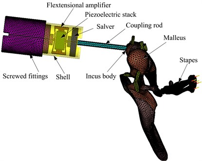
The material properties of the actuator’s other components were the same as that of the flextensional amplifier, that is, its density was 4430 kg/m3, Young’s modulus was 116 GPa, and Poisson’s ratio was 0.32. In the coupling FE model, the piezoelectric stack was meshed by 16603 hexahedral elements. The flextensional amplifier was meshed by 59942 tetrahedral elements. The screwed fitting was composed of three cylinders, a total of 26834 tetrahedral elements were created to mesh it. The slaver, which connected between the coupling rod and the flextensional amplifier, was consisted of two cylinders. A total of 7275 tetrahedral elements were created to mesh the slaver. The shell was meshed by 18115 tetrahedral elements. And the coupling rod was meshed by 5212 tetrahedral elements. Since the tip of the coupling rod was placed in a laser-drilled hole in the incus body and fixed to it by bone cement during the surgery [31, 32], the connection between the coupling rod’s tip and the incus body was modeled by coupling the corresponding FE nodes of them.
Table 5Dimension parameters of the flextensional piezoelectric actuator’s other structures
Components | Diameter (mm) | Length (mm) |
Screwed fittings | ||
Small cylinder | 1.2 | 0.4 |
Medium cylinder | 3.2 | 0.6 |
Large cylinder | 4 | 4.5 |
Slaver | ||
Small cylinder | 1.2 | 0.4 |
Large cylinder | 3.2 | 0.6 |
Shell | 3.6 | 4.2 |
Coupling rod | 0.5 | 6 |
3.2.3. The determination of the piezoelectric stack’s layer number
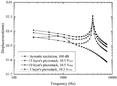
High sound intensity will pain the patients [33], thus stapes displacement driven by the acoustic excitation of 100 dB SPL is often used as the MEI’s hearing compensation standard [12, 33]. This value was also taken as the design standard in this paper, and the maximum driving voltage of the piezoelectric actuator was set to 10.5 [34]. Based on the established coupling mechanical model, the effect of the piezoelectric stack’s layer number on the actuator’s performance was obtained as shown in Fig. 8. It shows that a 10 layers’ piezoelectric stack for the flextensional piezoelectric actuator was sufficient to stimulate the stapes displacement equivalent to the one excited by 100 dB SPL at the tympanic membrane. Therefore, the layer number of the actuator’s piezoelectric stack was determined to be 10.
Fig. 8Stapes displacements driven by the acoustic excitation and the actuator excitation
3.3. Equivalent sound pressure level of the actuator
In the field of middle ear implant, the equivalent sound pressure level is usually used to evaluate its hearing compensation behavior [13, 35]. We also utilized this index to study the performance of our proposed flextensional piezoelectric actuator. The equivalent sound pressure level was calculated by Eq. (6):
where is the stapes displacement under actuator excitation, and is the stapes displacement under acoustic excitation of 100 dB SPL at tympanic membrane.
Fig. 9Equivalent sound pressure level of the flextensional piezoelectric actuator
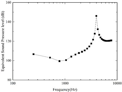
Our model-predicted result was shown in Fig. 9. It demonstrates that our designed flextensional piezoelectric actuator can generate about 100 dB SPL equivalent sound pressure under the driving voltage of 10.5 below 1 kHz, 109 dB at 2 kHz, 146 dB at 4 kHz. The equivalent sound pressure level of the actuator significantly increased from 1 kHz to 4 kHz, and this increase was more significant at 4 kHz. Considering the sensorineural hearing loss is most severe at high frequencies [1], it is very beneficial to the patient's hearing compensation.
3.4. The power consumption of the actuator
Middle ear implant belongs to implanted devices, so its power consumption should be restricted. Therefore, the power consumption of the piezoelectric actuator was also analyzed. Since this piezoelectric actuator works far below its resonance frequency, its behavior can be approximated to that of a capacitor [13]. And its capacitance can be estimated by summing each single layer’s capacitance as follows:
where is the absolute permittivity in free space, 8.85419×10⁻¹² C/V m, is the relative permittivity of the dielectric, is the electrode surface area, is the layer number of the piezoelectric stack, and is the single layer thickness. According to the material properties and structural size of the actuator’s piezoelectric stack, the capacitance value is calculated to be 0.71 nF by the Eq. (7). To simplify the power comsumption estimation for the piezoelectric actuator, we neglected the influence of the external force [36]. Experimental results showed that this simplification induced a difference less than 3 % [36], which meets the accuracy requirements of our study. When the actuator is excited with a sine voltage , its current and corresponding power consumption at a frequency are given by:
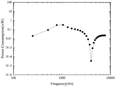
Based on our constructed coupling mechanical model, the required driving voltage for the piezoelectric actuator to stimulate an equivalent displacement of 100 dB SPL was derived firstly, and then the corresponding power consumption of the actuator was calculated by Eqs. (8-9). Fig. 10 shows our model-predicted result. It indicates that to stimulate the vibration of ossicles to the equivalent of 100 dB SPL, the maximum power consumption of our designed actuator is about 0.33 mW (at 1 kHz), which is reasonable for middle ear implants. According to Wang et al.’s report [13], the power consumption of their designed piezoelectric stack actuator was about 0.7 mW under the driving voltage of per volt at 1 kHz. However, the power consumption of our designed actuator was only about 0.003 mW under the driving voltage of per volt at 1 kHz, which showed a significant reduction in the actuator’s power consumption after the introduction of the flextensional amplifier.
Fig. 10Power consumption of the flextensional piezoelectric actuator
4. Conclusions
To solve the problem of high power consumption of the piezoelectric stack actuator for the incus-body driving type middle ear implant, a novel flextensional piezoelectric actuator was proposed and designed in this paper. The proposed actuator consisted of a fixator, a screwed fitting, a flextensional amplifier, a piezoelectric stack, a slaver, a shell and a coupling rod, can be implanted into the mastoid cavity by a surgical procedure similar to Otologics MET ossicular stimulator. To aid the design of the actuator, a human middle ear finite element model, which considers the viscoelastic properties of its soft tissues, was established and verified. Our study demonstrates that the incorporation of the viscoelastic properties of its soft tissues does improve the model-predicted stapes displacement at high frequencies. Then, based on this improved model, a coupling FE model of the human ear and the flextensional piezoelectric actuator was constructed. And the coupling FE model was utilized to aid the design of the actuator, and analyze the actuator’s equivalent sound pressure level and power consumption.
In consideration of the anatomical dimensions of human mastoid cavity, the flextensional piezoelectric actuator was minimized to a 4.5 mm diameter. The layer number of the piezoelectric stack was set to 10 based on the calculation of the coupling FE model. The results show that the designed actuator, which is driven by a voltage of 10.5 Vrms, can generate equivalent sound pressure of about 100 dB SPL, and compensate higher level hearing loss. Besides, the actuator presented a superior performance at higher frequencies, which benefits its compensation for sensorineural hearing loss since the most common sensorineural hearing loss is a high-frequency hearing loss. In terms of the power consumption, the designed piezoelectric actuator has a maximum value of 0.33 mW at 1 kHz for exciting an ossicular vibration equivalent to 100 dB SPL. This value is much less than that of electromagnetic middle ear implants. Moreover, under the driving voltage of per volt at 1 kHz, the power consumption decreased significantly from previous piezo-stack actuator’s 0.7 mW to our proposed actuator’s 0.003 mW. The study of this paper will be beneficial to structural optimization for middle ear implant and further study on fully-implantable middle ear hearing devices.
In the subsequent study, we will fabricate the flextensional piezoelectric actuator and build an experimental platform, which mainly consists of human temporal bone, laser vibrometer, and data acquisition system, to test its actual hearing compensation performance.
References
-
Moore B. Cochlear Hearing Loss. 2nd Edition, John Wiley and Sons, Chichester England, 2007.
-
Meister H., Lausberg I., Kiessling J., Walger M., Von W. H. Determining the importance of fundamental hearing aid attributes. Otology and Neurotology, Vol. 23, Issue 4, 2002, p. 457-462.
-
Azadarmaki R. Middle ear implants: a review of fully implantable and semi implantable devices. Otorinolaringol, Vol. 64, Issue 4, 2014, p. 167-177.
-
Liu H. G., Rao Z. S., Huang X. S., Cheng G., Tian J. B., Ta N. An incus-body driving type piezoelectric middle ear implant design and evaluation in 3d computational model and temporal bone. Scientific World Journal, 2014, p. 121624.
-
Zenner H. P., Leysieffer H. Total implantation of the implex tica hearing amplifier implant for high-frequency sensorineural hearing loss: the tübingen university experience. Otolaryngologic Clinics of North America, Vol. 34, Issue 2, 2001, p. 417-446.
-
Kontorinis G., Giesemann A. M., Witt T., Goetz F., Schwab B. Controlling the position and the dislocation of the middle ear transducer with high-resolution computed tomography and digital volume tomography: implications for the transducers’ design. European Archives of Oto-Rhino-Laryngology, Vol. 269, Issue 4, 2012, p. 1103-1110.
-
Goll E., Dalhoff E., Gummer A. W., Heyd A., Wildenstein D., Arnold H., Schraven S. P., Kaltenbacher D., Schächtele J., Schäfer A., Burkhardt C., Tavakoli K., Brenk U., Pojtinger A., Remer U., Wesendahl T., Winter M., Zenner H. P. Concept and evaluation of an endaurally insertable middle-ear implant. Medical Engineering and Physics, Vol. 35, Issue 4, 2013, p. 532-536.
-
Kaltenbacher D., Schächtele J., Goll E., Burkhardt C., Arnold H., Dalhoff E., Zenner H. P. Design study of a miniaturized displacement transducer (mdt) for an active middle ear implant system. Biomedical Microdevices, Vol. 16, Issue 6, 2014, p. 805-814.
-
Dong H. S., Seong K. W., Puria S., Lee K. Y., Cho J. H. A tri-coil bellows-type round window transducer with improved frequency characteristics for middle-ear implants. Hearing Research, Vol. 341, 2016, p. 144-154.
-
Gan R. Z., Dai C., Wang X., Nakmali D., Wood M. W. A totally implantable hearing system – design and function characterization in 3d computational model and temporal bones. Hearing Research, Vol. 263, Issues 1-2, 2010, p. 138-144.
-
Ball G. R. The vibrant soundbridge: design and development. Advances in oto-rhino-laryngology, Vol. 69, 2010, p. 1-13.
-
Hong E. P., Kim M. K., Park I. Y., Lee S. H., Roh Y., Cho J. H. Vibration modeling and design of piezoelectric floating mass transducer for implantable middle ear hearing devices. Ieice Transactions on Fundamentals of Electronics Communications and Computer Sciences, Vol. E90-A, Issue 8, 2007, p. 1620-1627.
-
Wang Z. G., Abel E. W., Mills R. P., Liu Y. Assessment of multi-layer piezoelectric actuator technology for middle-ear implants. Mechatronics, Vol. 12, Issue 1, 2002, p. 3-17.
-
Shih W. Y., Shih W. H., Aksay I. A. Scaling analysis for the axial displacement and pressure of flextensional transducers. Journal of the American Ceramic Society, Vol. 80, Issue 5, 1997, p. 1073-1078.
-
Yu J. F., Chen C. I. Modeling the dynamic characteristics of human ossicles. Journal of Vibroengineering, Vol. 14, Issue 4, 2012, p. 1494-1499.
-
Xu D., Liu H. G., Zhou L., Cheng G., Yang J. H., Huang X. S., Liu X. L. The effect of actuator and its coupling conditions on eardrum-stimulated middle ear implants: A numerical analysis. Proceedings of the Institution of Mechanical Engineers Part H: Journal of Engineering in Medicine, Vol. 230, Issue 12, 2016, p. 1074-1085.
-
Zhou L., Feng M. L., Wang W., Tong H., Liu J. P., Gao L., Huang X. S. Study on the role of ossicular joint using finite element method. Journal of Mechanics in Medicine and Biology, Vol. 16, Issue 4, 2016, p. 1650041.
-
Gentil F., Parente M., Martins P., Garbe C., Jorge R. N., Ferreira A., Tavares J. M. The influence of the mechanical behaviour of the middle ear ligaments: a finite element analysis. Proceedings of the Institution of Mechanical Engineers Part H Journal of Engineering in Medicine, Vol. 225, Issue 1, 2011, p. 68-76.
-
Kirikae I. The Structure and Function of the Middle Ear. University of Tokyo Press, Tokyo, Japan, 1960.
-
Herrmann G., Liebowitz H. Mechanics of Bone Fractures. Academic Press, New York, 1972, p. 772-840.
-
Gan R. Z., Sun Q. L., Feng B., Wood M. W. Acoustic-structural coupled finite element analysis for sound transmission in human ear--pressure distributions. Medical Engineering and Physics, Vol. 28, Issue 5, 2006, p. 395-404.
-
Gan R. Z., Sun Q. L., Jr D. R., Chang K. H., Dormer K. J. Three-dimensional modeling of middle ear biomechanics and its applications. Otology and Neurotology, Vol. 23, Issue 3, 2002, p. 271-280.
-
Zhang X. M., Gan R. Z. A comprehensive model of human ear for analysis of implantable hearing devices. IEEE Transactions on Biomedical Engineering, Vol. 58, Issue 10, 2011, p. 3024-3027.
-
Machiraju C., Phan A. V., Pearsall A. W., Madanagopal S. Viscoelastic studies of human subscapularis tendon: relaxation test and a Weichert model. Computer Methods and Programs in Biomedicine, Vol. 83, Issue 1, 2006, p. 29-33.
-
Zhang J., Tian J. B., Ta N., Huang X. S., Rao Z. S. Numerical evaluation of implantable hearing devices using a finite element model of human ear considering viscoelastic properties. Proceedings of the Institution of Mechanical Engineers Part H Journal of Engineering in Medicine, Vol. 230, Issue 8, 2016, p. 784-794.
-
Gan R. Z., Wood M. W., Dormer K. J. Human middle ear transfer function measured by double laser interferometry system. Ontology and Neurotology, Vol. 25, Issue 4, 2004, p. 423-435.
-
Zhang X., Gan R. Z. Finite element modeling of energy absorbance in normal and disordered human ears. Hearing Research, Vol. 301, Issue 7, 2013, p. 146-155.
-
Lerch R. Simulation of piezoelectric devices by two and three-dimensional finite elements. IEEE Transactions on Ultrasonics Ferroelectrics and Frequency Control, Vol. 37, Issue 3, 1990, p. 233-247.
-
Ostergaard D. F., Pawlak T. P. Three-dimensional finite elements for analyzing piezoelectric structures. IEEE Ultrasonics Symposium, Williamsburg, USA, 1986, p. 639-644.
-
Maassen M. M., Lehner R. L., Müller G., Reischl G., Lüdtke R., Leysieffer H., Zenner H. P. Adjusting the geometry of implantable hearing aid components to human temporal bone. I: Electromechanical transducer. HNO, Vol. 45, Issue 10, 1997, p. 840-846.
-
Jenkins H. A., Atkins J. S., Horlbeck D., Hoffer M. E., Balough B., Arigo J. V., Alexiades G, Garvis W. US phase I preliminary results of use of the otologics MET fully-implantable ossicular stimulator. Otolaryngology – Head and Neck Surgery, Vol. 137, Issue 2, 2007, p. 206-212.
-
Leysieffer H., Baumann J. W., Müller G., Zenner H. P. An implantable piezoelectric hearing aid transducer for inner ear deafness. II: Clinical implant. HNO, Vol. 45, Issue 10, 1997, p. 801-815.
-
Park S., Lee K. C. Design and analysis of a microelectromagnetic vibration transducer used as an implantable middle ear hearing aid. Journal of Micromechanics and Microengineering, Vol. 12, Issue 5, 2002, p. 505-511.
-
Laursen W. Breaking the sound barrier. Engineering and Technology, Vol. 1, Issue 3, 2006, p. 38-41.
-
Wang Z. G., Mills R. P., Luo H. L., Zheng X. L, Hou W. S., Wang L. J., Brown S. I., Cuschieri A. A micropower miniature piezoelectric actuator for implantable middle ear hearing device. IEEE Transactions on Bio-Medical Engineering, Vol. 58, Issue 2, 2011, p. 452-458.
-
Brennan A. M. C., Mcgowan A. M. R. Piezoelectric power requirements for active vibration control. Proceedings of SPIE, The International Society for Optical Engineering, Vol. 114, Issue 9, 1997, p. 1542-1570.
Cited by
About this article
This work supported by the Fundamental Research Funds for the Central Universities (2017QNA19), the Top-notch Academic Programs Project of Jiangsu Higher Education Institutions, and the Priority Academic Program Development of Jiangsu Higher Education Institutions.
Author’s contributions are as follows. Houguang Liu: drafting the article and analyzing the data. Mengli Wang: design of the work and modeling the coupling mechanical model. Xinsheng Huang: modeling the human middle ear FE model. Jianhuang Yang: data analysis. Lei Zhou: modeling the human middle ear FE model.

