Abstract
In this paper, the design and fabrication of the novel single-mode piezoelectric actuator with asymmetric electrodes are presented. The accomplishment of this study is to enlarge the vibrating amplitude of the pusher on the piezoelectric actuator by finding the optimal design factors combination of the piezoelectric actuator. By using finite element analysis software, this study simulated the vibration mode and amplitude of piezoelectric actuators. The Taguchi method was used to design the parameters of the novel piezoelectric actuators. From the simulation experiment results, the optimal dimensions of the piezoelectric plate are 20×10×1 mm with 12 mm exciter electrode length. This paper also presents a discussion regarding the influence that the design parameters had on the actuator amplitudes. Based on optimal design parameters, this study produced a novel piezoelectric actuator and tested the thrust force, confirming that actuators provide a greater thrust force than that of traditional actuators.
1. Introduction
Compared with electromagnetic actuators, piezoelectric actuators have many advantages, including large output torques, no gearbox or brake mechanism required, bearing-less, quick response, no backlash, high positioning resolution, absence of magnetic fields, simple structure, linear direct driving, small volume, low power consumption and high positioning accuracy. That is why piezoelectric actuators are widely used in the industry. Many applications using piezoelectric actuators can be found in our daily life such as the pick-up system, the atomizing device, the medical nebulizer, the zooming system and the image stabilization system in the digital camera.
An piezoelectric linear motor for light pick-up element application was presented in 1993. The ultrasonic linear motor was used to drive a light pick up element of CD-ROM. The ultrasonic linear motor feature of an inner square hole could combine extensional and bending mode. This method makes the possible independently excitation of both modes [1]. A new design of micro-nebulizer, integrating a piezoelectric actuator, micro-nozzle plate, and the cavity of the micro pump to achieve a high-quality atomizing effect was presented in 2008 [2-3]. Another cymbal-shaped high power micro-actuator for nebulizer application was presented in 2010. The ring-type piezoelectric plate and cymbal-shaped micro nozzle plate were used in the medical micro-nebulizer. The cymbal-shaped feature of the micro nozzle plate could focus the energy on the center of it and induce a large output force, which provides the cymbal-shaped micro-actuator with high power to spray medical solutions of high-viscosity produce ultra-fine droplets and increase the atomization rate [4-5]. In addition, some piezoelectric motors also could be used to moving lens and the image sensor in the zooming and of the digital camera. A piezoelectric element based smooth impact drive mechanism (SIDM) was presented in 1997 [6]. The mechanism was a linear actuator that utilized the rapid expansion or contraction of a piezoelectric element and the friction between a rod which was attached to the piezoelectric element and a mobile body. The proposed actuator, small and capable of being driven with high precision, may be used to swing the lens or image sensor in image stabilization system which could compensate the hand shake effect [7-8]. A butterfly-shaped ultra slim piezoelectric linear motor for zooming mechanism application was presented in 2011. The wing-type piezoelectric plate was used in thin electric products such as cell-phones or PDAs. The wing-type feature of the coupling tip with elastic plate could combine longitudinal and transverse vibration mode, which provides the butterfly motor minimize the thickness [9]. A 3D piezoelectric actuator with multi-degree of freedom for machine vision application was presented in 2013. The proposed actuator was principally aiming to overcome the visual spotlight focus angle of digital visual data capture transducer, digital cameras and enhance the machine vision system ability to perceive and move in 3D [10].
More and more piezoelectric actuators were developed for certain application in recent years. However, the core characteristics required of piezoelectric actuators are the same. Actuators at these scales require high output forces, accuracy, low response times, a simple design and simple operation [11]. The piezoelectric ultrasonic motors can be divided into two categories: standing wave ultrasonic motors (SWUM) and traveling wave ultrasonic motors (TWUM), since the key differentiation in the design of piezoelectric ultrasonic actuators is the method by which the stator converts the motion of the piezoelectric elements to the elliptical stator tip motion. The SWUM rely on the standing waves to produce motion and it is simple to design and build. The TWUM produce motion by means of the superposition of standing waves in the stator. A single-mode piezoelectric actuator for ultrasonic linear motor was developed in 2005 [12]. The friction element, as the driving tip, was attached at the midpoint of the long edge of the piezoelectric plate. The two-dimensional standing wave would occur at the midpoint of the long edge of the piezoelectric plate when the actuator was excited asymmetrically. The superposition of the two-dimension standing wave would produce the cyclic motion. With a proper preload, the piezoelectric actuator would push the linear slider. In the theory, a piezoelectric actuator would have better performance if the pusher on the piezoelectric actuator would have the larger vibrating amplitude. However, it is difficult to design a high performance piezoelectric actuator with asymmetric electrodes since each dimension of the piezoelectric plate will inflect the vibrating amplitude of the pusher on the piezoelectric ultrasonic actuator.
2. Design concepts
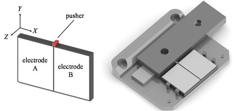
The conventional piezoelectric actuator and the linear stage driven by it are shown as Fig. 1. The actuator consists of a piezoelectric plate polarized in the Z direction and a pusher attached on long edge of the piezoelectric plate. The electrodes are set on the large surfaces (X-Y planes) of the plate. There are two symmetric electrodes, as the exciter electrodes, on one surface and each electrode covers one half of the surface. There is only one electrode, as the common drain, on the opposite surface. The pusher is attached at the mid-point on the long edge of the piezoelectric plate.
Fig. 1Conventional piezoelectric actuator and the linear stage driven by it
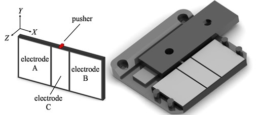
A novel piezoelectric actuator with asymmetric exciter electrode is developed in this study since the larger exciter electrode is expected. The basic design concepts of the novel piezoelectric actuator and the linear stage driven by it are shown as Fig. 2. Comparing with conventional piezoelectric actuator in Fig. 1, the electrodes on the front surface of the piezoelectric plate are divided into A, B and C three parts. The other surface still has only one electrode as a common drain, and the pusher is attached on the long edge of the piezoelectric plate.
Fig. 2Novel piezoelectric actuator and the linear stage driven by it
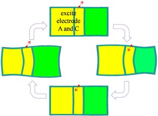
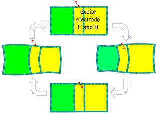
The vibration modes of the novel piezoelectric actuator with asymmetric electrodes are shown as Fig. 3. When the actuator is excited by both of electrode A and electrode C on the front surface with the electrode B is left floating, the vibration mode of piezoelectric actuator is shown as Fig. 3(a). The pusher will vibrate along the +X and +Y direction under this operating mode. When the actuator is excited by both of electrode C and electrode B on the front surface with the electrode A is left floating, the vibration mode of piezoelectric actuator is shown as Fig. 3(b). The pusher will vibrate along the -X and +Y direction under this operating mode. The output performance such thrust and speed would be better if vibrating amplitude of the pusher is lager. Therefore, it is very important to investigate the design parameters of the piezoelectric actuator that affect the vibrating amplitude of the pusher.
Fig. 3Operation modes of the novel piezoelectric actuator with asymmetric electrodes
a)
b)
3. Simulation experiments and results
Taguchi method, kind of design of experiment, is a statistical method developed by Dr. Taguchi to improve the quality of a product or a manufacturing process. It has been used to improve quality of products in industries for a long time. It is usually used to obtain the optimal combination of design factors by tools such as S/N ratio and orthogonal arrays. In this study, the Taguchi method is used to find out the optimal design factors of the piezoelectric actuator by the simulation experiments [13]. The PZT material properties are provided by the manufacturing company of PZT in Taiwan (Eleceram Technology Co., Ltd. and Internet Web is www.eleceram.com.tw). Those material properties as d31, electromechanical coupling coefficient, quality factor, and density were 171 pm/v, 0.34, 1800, and 7.75 g/cm3, respectively.
The detailed method for the simulation experiments in this study including three steps: modal analysis, harmonic analysis, and design factors optimization. First, the exciting frequency of the piezoelectric plate can be fine by the modal analysis. Second, the harmonic analysis can show the amplitude of pusher of the piezoelectric actuator. Finally, the optimal combination of design factors can be obtained by the Taguchi method. In this study, the “vibrating amplitude of the pusher on the piezoelectric plate” is chosen to be the quality characteristic. By a brainstorming in early design stage, all possible design parameters that affect the “vibrating amplitude of the pusher on the piezoelectric plate” were considered. The four chosen design factors and their levels for the experiment are shown in Table 1. An L18 orthogonal array is used to set the levels of design factors.
Table 1The design factors and levels table (original design)
Factor | Level 1 | Level 2 | Level 3 |
Length (B) | 12 mm | 16 mm | 20 mm |
Width (C) | 8 mm | 10 mm | 12 mm |
Thickness (D) | 1 mm | 1.5 mm | 2 mm |
Electrode length (E) | 0.4 L | 0.5 L | 0.6 L |
The larger vibration amplitude of pusher is expected because a piezoelectric actuator with larger vibration will have better output performance. In this study, the quality characteristic is larger-the-better. We seek to maximize the vibrating amplitude of the pusher on the piezoelectric plate. The larger-the-better S/N ratio, based on the reciprocal of the smaller-the-better loss function, is defined by:
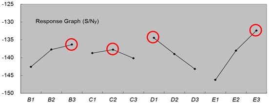
Table 2 and Table 3 are the factor effects responses tables. The factor effects plots are shown as Fig. 4 and Fig. 5. The S/Nx and S/Ny are the S/N ratio of the quality characteristics in X-direction and Y-direction respectively. Among of the factors and levels, it is obvious that each factor is influential. Therefore, all the factors are considered as the significant factors. The biggest S/N ratio, both in X-direction and Y-direction, will occur with following combination of factors: B3, C2, D1, and E3. The third level of factor B is 20 mm (the length of piezoelectric plate). The second level of factor C is 10 mm (the width of piezoelectric plate). The first level of factor D is 1 mm (the thickness of piezoelectric plate). The third level of factor E is 12 mm (the electrode length of piezoelectric plate). Therefore, the optimal combination of control factors B, C, D, and E are B3, C2, D1, and E3. This is also the combination of design factors of the 17th experiment in the L18 orthogonal array experiments.
Table 2The S/Nx ratio response table
Levels | Factors | |||
Length (B) | Width (C) | Thickness (D) | Electrode length (E) | |
1 | –163.40 | –150.53 | –144.32 | –157.38 |
2 | –145.15 | –150.62 | –154.85 | –150.34 |
3 | –144.90 | –152.29 | –154.27 | –145.72 |
Table 3The S/Ny ratio response table
Levels | Factors | |||
Length (B) | Width (C) | Thickness (D) | Electrode length (E) | |
1 | –142.58 | –138.72 | –134.45 | –146.24 |
2 | –137.74 | –137.75 | –139.00 | –138.02 |
3 | –136.35 | –140.18 | –143.20 | –132.40 |
Fig. 4The factor effects response plot of S/Nx
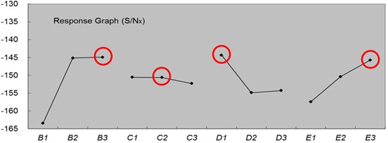
Fig. 5The factor effects response plot of S/Ny
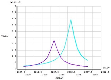
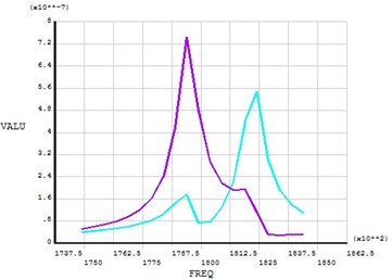
The simulation results of the original design and optimal design are shown as Fig. 6(a) and Fig. 6(b) respectively. After the simulation experiments and the design optimization process, the vibrating amplitude of the pusher on the piezoelectric plate in the X-direction is from 0.63 μm reducing to 0.54 μm and the vibrating amplitude of the pusher on the piezoelectric plate in the Y-direction is from 0.37 μm raising to 0.73 μm.
Fig. 6a) The simulation results of original design, b) The simulation results of optimal design
a)
b)
4. Fabrication and testing
The vibrating amplitudes of the pusher in the X-direction and in the Y-direction along the length of piezoelectric plate are shown as Fig. 7. It appears that the vibrating amplitudes vary along the length direction of piezoelectric plate in the figure. The pusher should be set on the points with maximum vibrating amplitude. On the other hand, the fixture should be set on the points with minimum vibrating amplitudes. After seeking the two curves in the Fig. 7, it appears that the maximum amplitude, both in the X-direction and in the Y-direction, of the piezoelectric actuator occurs at the position of 10 mm. Therefore, the pusher is set at this position. The minimum amplitudes, both in the X-direction and the Y-direction, of the piezoelectric actuator occur at the positions of 4 mm and 16 mm. Therefore, the two fixtures are set at these positions. Fig. 8 shows the detail dimensions of the piezoelectric actuator. The dimensions of the piezoelectric plate are 20×10×1 mm and the dimensions of electrodes on the front surface of the piezoelectric plate are 8 mm, 4 mm, and 8 mm.
Fig. 7The vibrating amplitudes in the X-direction and the Y-direction along the length of piezoelectric plate
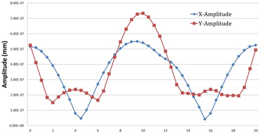
Fig. 8The detail dimensions of the piezoelectric actuator with asymmetric electrode
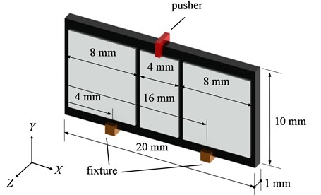
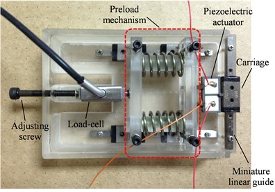
Fig. 9 is linear stage using the novel piezoelectric actuator. The linear stage consists of a force piezoelectric actuator, a miniature linear guide, a uniaxial load-cell, the preload mechanism, and an adjusting screw. The pushers contact with the carriage on the linear guide. The preload mechanism is set on the other side and contacts with the fixtures on the piezoelectric actuator. By adjusting the screw, the preload mechanism will press the piezoelectric actuator toward the direction of linear guide to produce a proper preload between the pushers and the carriage. The preload can be measured by the load-cell.
Fig. 9The linear stage using the novel piezoelectric actuator
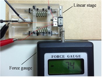
In this study, the thrusts force of novel piezoelectric actuator and the conventional piezoelectric actuator are measured. The drive signal generated by a function generator is supplied to the piezoelectric actuator through a power amplifier and an oscilloscope is used to monitor the drive signal. A force gauge is used to measure the thrust force of the linear stage as the piezoelectric actuator is excited. Fig. 10 shows the thrust measurement experiments.
Fig. 10Thrust measurement experiments
The resonance frequency of piezoelectric actuator obtained by simulation is about 222 kHz. The actual operating frequency is about 218 kHz after the actuator is assembled in the linear stage. After initial testing, the appropriate preload of 215 g is chosen. Too large or small preload will influence the normal operating of the actuator. The thrusts forces of the linear stage with the preload of 215 g and the drive voltage 30 Vpp are shown in Table 4. From the results in the table, the average thrust forces of the conventional piezoelectric actuator and novel piezoelectric actuator are 69.4 g and 97.8 g, respectively. The thrust force of novel piezoelectric actuator is larger than the thrust force of conventional piezoelectric actuator by 40 %. From the above experimental results, it appears that the novel piezoelectric actuator can provide a larger thrust force.
Table 4Thrusts of the conventional and the novel piezoelectric actuators (215 g preload, 30 Vpp exciter voltage)
Test 1 (g) | Test 2 (g) | Test 3 (g) | Test 4 (g) | Test 5 (g) | Ave. thrust (g) | |
Conventional design | 64 | 68 | 72 | 73 | 70 | 69.4 |
New design | 101 | 93 | 99 | 96 | 100 | 97.8 |
5. Conclusions
In this paper, the design and fabrication of the novel piezoelectric actuator with asymmetric electrode are presented. The main purpose of this study is to find the optimal design factors of the piezoelectric plate that have the largest vibrating amplitude of the pusher on the piezoelectric actuator. From the simulation experiment results, the main factors to influence the vibrating amplitude of the pusher on the piezoelectric actuator are the length of the piezoelectric plate and the electrode length. The optimal dimensions of the piezoelectric plate are 20×10×1 mm with 12 mm electrode length. The vibrating amplitude of the pusher on the conventional piezoelectric actuator in the X-direction and Y-direction are 0.63 μm and 0.37 μm respectively. After the design optimization process, the vibrating amplitude of the pusher on the novel piezoelectric actuator in the X-direction and Y-direction are 0.54 μm and 0.73 μm respectively. Moreover, the novel piezoelectric actuator is also used to develop a linear stage in this study. Some thrusts measurement experiments are carried out. From the experiment results, the novel piezoelectric actuator can provide a greater thrust force than that of conventional actuators under the same preload. Comparing with the thrust force of conventional piezoelectric actuator, the thrust force of novel piezoelectric actuator is larger than the thrust force of conventional piezoelectric actuator by 40 %.
References
-
Takehiro Takano, Yoshiro Tomikawa, Manabu Aoyagi, Toshiharu Ogasawara, Akira Yabuki Ultrasonic linear motors for application to driving a light pick-up element. Ultrasonic Symposium, Vol. 1, 1993, p. 445-448.
-
Sheng-Chih Shen, Yu-Jen Wang, Yung-Yue Chen Design and fabrication of medical micro-nebulizer. Sensors & Actuators A, Vol. 144, 2008, p. 135-143.
-
Pan C. T., Shiea J., Shen S. C. Fabrication of an integrated piezo-electric micro-nebulizer for biochemical sample analysis. Journal of Micromechanics and Microengineering, Vol. 17, 2007, p. 659-669.
-
Shen S. C. A New cymbal-shaped high power microactuator for nebulizer application. Microelectronic Engineering, Vol. 87, 2009, p. 89-97.
-
Strayer B. A., Dunn-Rankin D. Toward a control model for manipulating the breakup of a liquid jet. Atomization and Sprays, Vol. 11, 2001, p. 415-431.
-
Ueyama M., Kuwama M., Nagata H. Lens barrel having a piezoelectric actuator for moving optical elements. U.S. Patent 5,675,444, 1997.
-
Kanbara T. Electro-mechanical transducer lens drive mechanism for a vibration compensating lens system. U.S. Patent 5,768,016, 1998.
-
Chang S. J., Wang Y. J., Chen Y. C., Wu T. F. Image-stabilization driving device. U.S. Patent 7,800,651, 2010.
-
Won-Hee Leea, Chong-Yun Kanga, Dong-Soo Paik, Byeong-Kwon Ju, Seok-Jin Yoon Butterfly-shaped ultra slim piezoelectric ultrasonic linear motor. Sensors and Actuators A, Vol. 168, 2011, p. 127-130.
-
Shafik M., Nyathi B., Fekkai S. An Innovative 3D ultrasonic actuator with multidegree of freedom for machine vision and robot guidance industrial applications using a single vibration ring transducer. International Journal of Engineering and Technology Innovation, Vol. 3, Issue 3, 2013, p. 168-179.
-
Watson B., Friend J., Yeo L. Piezoelectric ultrasonic micro/milli-scale actuators. Sensors & Actuators A, Vol. 152, 2009, p. 219-233.
-
Oleksiy Vyshnevskyy, Sergej Kovalev, Wladimir Wischnewskiy A novel, single-mode piezoelectric plate actuator for ultrasonic linear motors. IEEE Transaction on Ultrasonics, Ferroelectrics, and Frequency Control, Vol. 52, Issue 11, 2005, p. 2047-2053.
-
Hung-Lung Lee, Shyang-Jye Chang, Sheng-Jye Hwang, Francis Su, Chang S. K. Computer-aided design of a TSOP II LOC package using Taguchi’s parameter design method to optimize mold-flow balance. Journal of Electronic Packaging, Vol. 125, 2003, p. 268-275.
About this article
The authors would like to thank Ministry of Science and Technology (MoST) for their financial supports to the project (granted number: NSC 101-2221-E-224-009).
