Abstract
A systematic method to analyze the trajectory of hook block for polar crane in nuclear power plant (NPP) is proposed, in which dynamic equations of the system and the compatibility conditions for drum parameters are presented. Properties and formulations of the variables involved in these equations are studied in detail. A method to describe the rope-pulley system is given and a numerical method is derived to solve the positions and velocities of the common tangents that consistent with the reeving ropes between spatial pulleys. Based on these displacements and velocities, the angular speeds of pulleys are given to solve the difficulty to confirm the rotating directions of pulleys in some rope-pulley systems. A numerical example contrasting the dynamic model with corresponding static model is demonstrated to validate the systematic method. The proposed method is largely universal and can be a reference for designing and analyzing of polar cranes in NPP.
1. Introduction
Nowadays varieties of cranes are widely used in industrial manufacture. With the rapid development of the modern science and technology, the expansion of industrial production and the improvement of automation, the requirements of crane are also growing, which makes the modern crane developed more durable, specialized and reliable. In particular working circumstance such as nuclear power plant, the polar cranes should locate the load in a high precision while replacing the reactor fuel or maintaining the heavy equipments. Taking some type of polar crane in service for example, the lateral displacement of the load should not be more than 5 mm while lifting 10 m height. To meet the accurate and reliable requirements, one should know how the load moves while the crane works.
There are many researches about cranes at present. Took the trolley moving into account, the controls of the load-deflections were studied in some literatures [1-3], while in literatures [4-6] the dynamic responses of the crane structure were discussed. These studies solved many problems on operation schemes and structural designs of the cranes, however, most of them simplified the rope-sheave system as a pendulum or double pendulum system, or considered the plurality of ropes as a flexible cable. In fact, the load’s movement is determined by the interactions between ropes and pulleys in the hoisting system. Though many achievements on the interactions have been accumulated, much work about combining the achievements with the large hoisting system of specific characteristics remains to be finished.
McDonald [7, 8] presented a pulley element for exact analysis of cables rolling on pulley, in which the internal forces and the tangent stiffness matrix corresponding to an equilibrium configuration are provided. Based on this study, further work aiming at the possible application to practical cable systems is advanced [9] and the finite element analysis with three-node element are conducted [10]. However, the pulley element was treated as a plane problem while deriving the internal force equilibrium in their researches. Aufaure [11, 12] presented a finite element formulation for a length of cable passing through a pulley to study the deformation and dynamic behavior of structures, which treated the pulley as a particle and neglected many details. Zhou [13] developed sliding cable elements and pulley models using the massless spring approach for the analysis of parachute systems. Ju [14] proposed a parameterized super element formulation for modeling the multiple-pulley cables; however, there was no further study about the movement of the pulley. Based on the concentrated-mass theory with multi-degree of freedom, Wang [15] analyzed the rope wound along helix and established a parametric model which is applicable to the case of less pulley. Hong [16] presented a program method to analyze the motion of complex cable-pulley mechanism, which could obtain the relationships of each variable; however, the method could not be applied to spatial rope-pulley system. In addition, most of the studies mentioned in this paragraph ignored the effect of pulley efficiency, which resulted in different tension values at two sides of a pulley [17, 18].
For the rope-pulley system, the load trajectory is determined by the hoisting speed, the layouts of the pulleys and the reeving ways of the ropes. Taking physical structure of the mechanism into account, a systematic method for analyzing the load trajectory of rope-pulley system is presented in the paper. In addition, the paper is organized as follows: In Section 2, the motion description and the dynamic equations are proposed. Section 3 gives the solution strategy for the tangent points and its velocities. In Section 4, the relationship of tensions at two sides of a pulley is discussed in detail. In Section 5, the compatible condition of rope length is supplement to solve the tangent points on drum. In Section 6, a method to solve the angular speeds of pulleys is proposed. In Section 7, a numerical example is given to demonstrate the application of the proposed method.
2. Dynamic equations for hook block
Generally, the hoisting mechanism of the polar crane in NPP consists of drum, fixed pulleys, movable pulleys mounted on hook block and ropes reeving through the pulleys. The rope outlet usually connects to the drum. For different engineering demands, the reeving way between rope and pulleys is different. Fig. 1(a) shows a reeving way as the rope goes through pulleys with one end connected to a drum, while the other dead-ended at a fixed point. Fig. 1(b) shows a reeving way as the rope branch goes through pulleys with two ends anchored to the two sides of the drum separately. The load ascends or descends in accordance with the drum winding or releasing the rope. It is obvious that the rotating directions of pulleys in Fig. 1(a) are clear; however, in Fig. 1(b) with separate rope branch the rotating directions of pulleys are difficult to confirm and should be solved firstly.
Fig. 1Schematic view of the polar crane in NPP
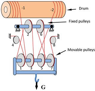
a) Rope-pulley system with two rope branches
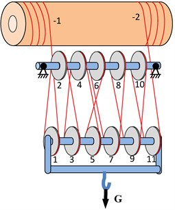
b) Rope-pulley system with separate rope branch
The external force on the hook block contains load weight, own gravity and contact forces between the ropes and the movable pulleys. Sum of these contact forces are approaching to the total tensions of the ropes connecting to the movable pulleys. However, the directions of the rope tensions probably change as the load hoisting, and the trajectory of the load would naturally be out of vertical and cause a lateral deflection. In fact, the trajectory is determined by the mechanic design, the layouts of the drum and pulleys, and the reeving ways of ropes. The bigger accelerator of the hook block causes a bigger deflection in general. Therefor as the system working, the operators should strive for a slow speed to keep the motion smooth for the hook block.
To describe the load trajectory, we create a reference coordinate system (e1,e2,e3) with origin located at the centroid of the hook block and (e1,e2,e3) is the initial coordinate system, which is the same direction with the global coordinate system. The corresponding current coordinate system is denoted by (e'1,e'2,e'3). The unit vectors e1, e2 and e3 toward the front, the right and the upward respectively as shown in Fig. 2. Regarding the hook block as a rigid body, its position can be described by the origin displacement u and the axial rotation θ at any given time. u and θ can be expressed in component forms as follows:
where u1 denotes the fore-and-aft trajectory, u3 denotes the right-and-left trajectory and h is the hoisting height.
Fig. 2Motion and stress of the hook block
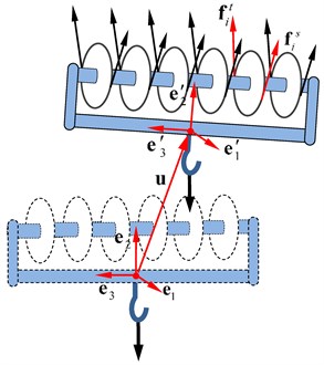
The variable θ describes the entire rotation of the hook block and it is so small that the relevant transforming matrix, which transforms a vector from the current coordinate system to the global coordinate system, can be approximated to [19]:
where E is 3×3 identity matrix and ˜θ is a skew symmetric matrix corresponding to θ:
Here and in after, ˜θ means the corresponding skew symmetric matrix of vector θ.
Denoting the mass of the load by mL, the hook block by mh, the external forces on the hook block includes the gravity (mL+mh)g, the tensions fti and fsi at both sides of each movable pulley as shown in Fig 2. Assuming the direction of the load weight on mount point of the hook block is vertical downward, the dynamical equation for the hook block can be obtained:
where ¨u, ˙ω are acceleration and rotating acceleration of the hook block respectively and:
J is rotational inertia of the hook block, ˉJi is rotational inertia relative to the shaft hi of the movable pulley i and ωi is the angular speed of the pulley. qc is the centroid vectors of the hook block, and qti, qsi are the vectors from qc to the contact points between the pulley i and the spatial ropes at the tight-side of the pulley and the slack-side of the pulley respectively in the current coordinate system. At initial, they are constant and denoted by ˉqc, ˉqti, ˉqsi respectively. Then we have the relations between the two sets of vectors:
It can be seen that the directions of the forces in Eqs. (5)-(6) are determined by the position of hook block and updated with the pace of load hoisting. If we remove the terms of velocities ω, ωi and accelerations ¨u, ˙ω in Eqs. (5)-(6), nonlinear equations for static model to solve the equilibrium path of the load will be obtained.
3. Tangent point between spatial pulleys and its velocity
In hoisting process, the rope starts to contact the pulley at the slack-side point and to leave the pulley at the tight-side point. The positions of the slack-side and tight-side points, which determine the application points and directions of rope tensions, are essential parameters to describe the rope-pulley system. Comparing to the load, the rope connecting two pulleys has a very small mass and can be considered as a straight line in space. Besides, the width of the pulley groove is quite small in contrast with the hoisting height. Therefore, we can treat the pulleys as spatial circles and the ropes as common tangents between the circles to solve the tangent points, which are the slack-side points and tight-side points.
Fig. 3Common tangent of two spatial pulleys
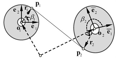
As shown in Fig. 3, we suppose two spatial circles with radii r1 and r2, denote their centers by the vectors o1, o2 respectively in the global coordinate, and establish the reference coordinates (e1,e2) and (ˉe1,ˉe2) in each circle’s surface. e3=e1×e2 and ˉe3=ˉe1×ˉe2 are the normal vectors of these circles. r1, r2 are the radius vectors from the circle centers to the corresponding tangent points. Generally, the distance between the two centers is bigger than the sum of the two radii. To describe the tangent point, the orientation angle is introduced as follows: taking circle o1 for example, a line coinciding with e1 rotates from e1 to the tangent point in the circle and sweeps out an angle β1; β1 is the orientation angle of the tangent point, whose range is [0,2π]. If we order x1=cosβ1, y1=sinβ1, x2=cosβ2 and y2=sinβ2, the radius vectors will be:
Since the common tangent is perpendicular with the radius vectors, we have:
Thus, the equation for common tangent is:
where the coefficient aij=ei∙ˉej,p1k=(o1-o2)∙ek,p2k=(o1-o2)∙ˉek. This is a nonlinear equation group hardly to get the analytical solution; meanwhile it is difficult to solve the numerical solution.
There are four types of common tangent between two spatial pulleys, separately called the common tangent of right external, left external, right internal and left internal corresponding to k= 1, k= 2, k= 3, and k= 4 as shown in Fig. 4. Therefor there are four solutions for the nonlinear Eq. (14) and it is meaningless that the solution is inconsistent with the type of the common tangent. To get the specified solution, we should take the initial value approximate to the specified solution as much as possible.
Fig. 4Types of the common tangent between pulleys
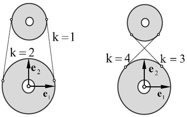
While the two spatial pulleys are coplanar or paralleled to each other, the equation for common tangent has analytical solutions. Then we take the corresponding analytical solution as the initial value to solve Eq. (14) for the specified solution. The method is proved feasible and effective. Thus, four initial values corresponding to the types of common tangent are written out as follows.
As for the external tangent, we have β2=β1, as shown in Fig. 5. Then, the common tangent of right external (k= 1):
Fig. 5External common tangent of pulleys
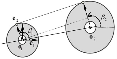
The common tangent of left external (k= 2):
where ρr=r2-r1, ρp=√p-ρ2r and p=p211+p212+p213.
As for the internal tangent |β2-β1|=π, we have the common tangent of right internal (k= 3):
The common tangent of left internal (k= 4):
where ρr=r2+r1, ρp=√p-ρ2r.
Taking Eqs. (15)-(18) as the initial value of Eq. (14), one can obtain the numerical solution consistent with the reeving way between the rope and pulleys.
The reeving way of each rope branch can be described by a matrix organized by two rows. The first row stores the numbers of the pulleys through which the rope reeves in sequence, while the second row stores the corresponding tangent types as shown in Fig. 4. For example, as to the hoisting system shown in Fig. 1(b) one could take the following matrix to describe the reeving way:
where –2 denotes right side of the drum. The left side of the drum is the starting point of the rope and does not appear in the matrix.
By the method above, the positions of the tangent points can be obtained. However, angular speed of the pulley in Eq. (6) should be solved as the plus-minus sign of the angular speed determines whether the side of the pulley is slack or tight. To solve the angular speed of the pulley, one should also know the velocities of the tangency points firstly. Obviously, the velocities are composed of the velocities following the reference coordinate on the pulley and the velocities relative to the coordinate and can be written as follows:
where ˙o1, ˙o2 are the center velocities of pulleys in global coordinate; ω1, ω2 are the rotational velocities of the body on which the pulley mounted; ˙β1, ˙β2 are the change rates of the orientation angles; t1, t2 are the tangent directions in the circles’ surface and can be expressed as follows:
In Eq. (14) we have that ˙y1=x1˙β1,˙x1=-y1˙β1,˙y2=x2˙β2,˙x2=-y2˙β2, and ˙w=t1∙m2˙β1+t2∙m1˙β2; therefore denoting q12=o1-o2 and ˙q12=˙o1-˙o2, one can obtain the change rates of the orientation angles by performing differentiation on the first two equations in Eq. (14):
Thus, it shows that the velocities of the tangent points in Eq. (20) have linear relationships with velocities and rotational velocities of the pulleys. Without loss of generality, if circle o1 represents fixed pulley, then ˙o1=0, ω1=0, while circle o2 represents movable pulley and ˙o2=˙u+ω×q2, ω1=ω∙q2 denotes the vector from centroid of the hook block to the center of the movable pulley.
4. Transmission of tensions at two sides of pulley
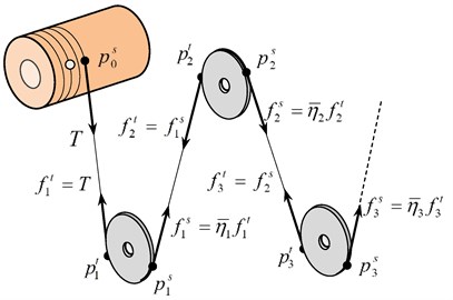
The rope in the branch can be divided into two parts: ropes wrapped on pulleys and ropes in space. Dividing points of the two parts are slack-side points psi and tight-side points pti as shown in Fig. 6. Generally, the pulley rotates slowly and the frictional force between the pulley and rope is big enough to prevent relative slip. In hoisting process, the rope transmits the rope tensions fsi and fti to the pulley.
The rope changes from straight line to curve at the slack side of the pulley, and changes from curve to straight line at the tight side. Because of the rope’s some resistance to deformation, there is a small transition curve between the straight line and the curve. The transition curve diminishes the distance between the straight rope and the pulley center at the tight side while extends the distance at the slack side. The diminished distance is denoted by δri, while the extended distance is approximated to δri, as shown in Fig. 7.
Fig. 6Slack-side point and tight-side point of the pulley
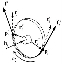
Fig. 7Stiffness resistance of rope
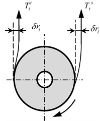
Regarding the pulley as a rigid body, the moment Mi on the pulley’s shaft hi can be written out as follows based on the dynamical equation for rigid body:
where rsi and rti are the vectors from the pulley’s center to the slack-side point and the tight-side point respectively. In the right sides of Eq. (23), the last term describes the gyro effect of the pulley which can be neglected as the hoisting speed is low and the inertia moment of the pulley is small relative to the hook block.
In the surface of the pulley, the corresponding tangent components of the rope tensions are:
Dot-multiplying both sides of Eq. (23) by the unit vector hi leads to the equation for moment equilibrium in direction of the pulley’s shaft:
In fact, the left term of the equation is resisting moment which is caused by friction between the pulley and the shaft and can be expressed by the frictional resistance coefficient ηf as follows:
In practical engineering, the value of ηf is usually between 0.014 and 0.0145 [20]. Mf is the moment that transmitted to the hook block. By ordering Mf=0 in Eq. (26), the increment of the tension at tight side can be obtained:
where the increment Tti-Tsi is caused merely by stiffness effect of the rope, and ηe is the stiffness resisting coefficient which is usually between 0.0055 and 0.06 in practical engineering [20]. And the relation between ηe and δ is:
Taking account of all the resistances, the relationship of the tensions at both sides of the pulley will be derived by Eqs. (26)-(29) as follows:
where η is efficiency coefficient.
According to Eqs. (24)-(25)and the previous analysis, the tensions at both sides of pulley satisfy the following expression:
where nsi, nti are the corresponding directions of the rope tensions.
Without considering rope mass, the tensions of the rope in space are equal at every point, and the rope tensions at both sides of pulleys satisfy Eq. (31) as shown in Fig. 8. Therefore, giving the tension of the rope connected the drum we can obtain the tension of each rope in space in sequence.
Fig. 8Directions of tensile forces and transitive relationships
5. Compatible condition of rope length
The common drum has a groove of helical line for the polar crane in NPP as shown in Fig. 9 and it is difficult to confirm the trajectory of the rope tangent point on the drum. In this section, compatible conditions of rope length are proposed to solve the trajectories of the rope tangent points with regard to duplex drum.
Fig. 9Rope length winded by the drum
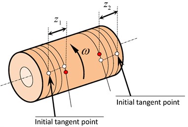
If the longitudinal displacement of the tangent point is zk (k= 1 stands for the left side of drum, k= 2 stands for the right side of drum), the length of the rope winded by the drum is:
where rd is the drum radius, d is the pitch of rope groove on the drum.
The total rope length in the branch is:
where n is the number of the ropes in space and li is the corresponding rope length which can be derived by the coordinates of tangent points; m is the number of the pulleys and si is the length of the rope wrapped on pulley i. si can be written out by multiplying the pulley radius ri by the wrap angle αi:
The wrap angle of pulley i can be expressed by the orientation angles as follows:
Taking the hoisting mechanism with separate rope branch as shown in Fig. 1(b) for example, the length of rope winded by the drum should equal to the length that reduced in the branch. Then we have:
where L0 is the initial length of the rope in the branch.
Though z1, z2 denote the longitudinal displacements on the same drum, they are not equal to each other strictly as the tangent points on the drum may move up and down in a certain range along the helical line. However, they can be expressed in the fellow forms:
where ϕ is the rotational angle of the drum, and β01, β02 are the initial orientation angles of the rope entries on the drum; β1, β2 are the current orientation angles of the rope entries and can be solved basing the method in Section 3 by treating the cross-sections of the drum as spatial circles.
By eliminating ϕ in Eq. (37), the relation between the two longitudinal displacements is derived as follows:
Eqs. (36) and (38) compose a pair of nonlinear equations that can be used to solve z1 and z2.
6. Angular speed of pulley
The rope speed is an important parameter for the selection of wire rope, the pulley design and the power system of drum, and cannot be estimated by multiplying factor for the hoisting system requiring precise control. Based on the velocities of tangent points obtained in Section 3, a method to resolve the rope speeds and the angular speeds of pulleys along the rope branch is proposed in this chapter.
Fig. 10Rope speed and angular speed of pulley
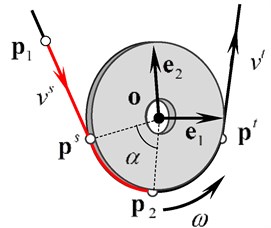
As shown in Fig. 10, the pulley of radius r and center o is described by the frame (e1,e2) in the surface of the pulley. ps, pt are the tangent points at the slack side and the tight side respectively. The rope for crane should have very high tensile strength, so it is reasonable to neglect the rope extension, which means that the length of the rope between any two points remains unchanged. Taking point p1 on the rope in space and point p2 on the adjacent rope wrapped on pulley for example, the rope length between the two points can be denoted as:
where l1 is the length of the rope in space between the two points and can be expressed as follows:
where ns is the unit direction vector of the rope and can be expressed by the tangent points. The change rate of l1 is:
where vs=˙p1∙ns is the rope speed at slack side of the pulley; ˙ps is the velocity of the tangent points.
l2 is the length of the rope wrapped on the pulley between p1 and p2, which can be expressed as follows:
where α is the wrapped angle;β2, βs are the orientation angles of p2, ps respectively. As p2 is consolidated on the pulley, the change rate of β2 is equal to the angular speed ω of the pulley. The change rate of l2 can be written as follows:
By the previous analysis, we know that ˙l1+˙l2=0. Then we can obtain:
The equation is the relationship of the angular speed ω and the rope speed vs at slack side of pulley. Similarly, the rope speed vt at tight side of the pulley can be expressed as follows:
And the difference between vs and vt is:
Using the change rates of the tangent points, the transitive relationship of the rope speeds at two sides of the pulley can be obtained by Eq. (46). In the rope branch, the rope speed is equal to zero if one end of the rope anchors to a fixed point; otherwise if the rope with an end connected to the drum, the rope speed can be solved from Eq. (44) in which ω becomes the angular speed of the drum and can be derived as follows:
where ˙z is the longitudinal velocity of the drum.
Therefore, starting from the end of the branch, one can obtain the rope speeds and the angular speeds of the pulleys successively by Eqs. (44)-(46).
7. Numerical example
In this section, a numerical example for a type of polar crane in NPP is given to verify the application of the methodology presented in this paper. As shown in Fig. 1(b), the hoisting mechanism has duplex drum with groove pitch 18 mm and separate rope branch; the global coordinate (X, Y, Z) is established as X towards front, Y towards up and Z towards left. The initial parameters including the diameters and positions of the drum and pulleys are displayed in Tables 1-2. Among the parameters, the positions of the movable pulleys are given in the hook-block-fixed coordinate, which was in the same direction with the global coordinate at initial. The efficiency coefficient of pulley is chosen as 0.98 as well as the frictional resistance coefficient is 0.01455. The weight of the hook block is 4800 Kg and the mount point is (0, –439, 0) mm in the hook-block-fixed coordinate.
Table 1Initial parameters of drum
Drum | Diameter (mm) | Pitch (mm) | Center coordinate (mm) | Direction of center trajectory |
Left | 1500 | 30 | (–1430, 640, 1800) | (0, 0, –1) |
Right | 1500 | 30 | (–1430, 640, –1800) | (0, 0, 1) |
Table 2Initial parameters of pulleys
Pulley | Number | Diameter (mm) | Center coordinate (mm) | Direction of rotate shaft |
Fixed pulley | 2 | 710 | (0, 0, 415) | (0, 0, 1) |
4 | (0, 0, 210) | |||
6 | (0, 0, 0) | |||
8 | (0, 0, –210) | |||
10 | (0, 0, –415) | |||
Movable pulley | 1 | 800 | (0, 550, 515) | (0, 0, 1) |
3 | 710 | (0, 550, 315) | ||
5 | 710 | (0, 550, 105) | ||
7 | 710 | (0, 550, –105) | ||
9 | 710 | (0, 550, –315) | ||
11 | 800 | (0, 550, –515) |
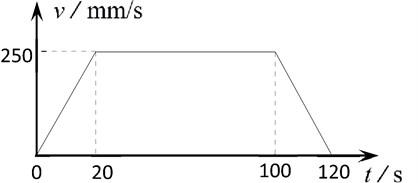
Through the analysis in this paper, there are seven unknown parameters in Eqs. (5)-(6): the kinematic parameter u1, h, u3, θ1, θ2, θ3 and the tension T of the drum, where the tension T is not easy to measure especially for the duplex drum. At the same time, the hoisting height h is an important and visually parameter and it can be formed a relationship of one-to-one mapping with time. Hence, we choose the hoisting height h as a known parameter to solve the model and describe the load trajectory. The hoisting speed versus the time was assumed as a trapezoidal curve as shown in Fig. 11, and a load of 100 t to arise 25 m at the initial position of (0, –30, 0) m was studied.
Fig. 11Hoisting speed versus time
The comparison of the proposed dynamic model and the corresponding static model for the centroid trajectories of the hook block versus hoisting height are plotted in Fig. 12-13.
It can be seen that: (1) The change trends of the two models are consistent and the hook block swings around the equilibrium path in the dynamic model. The initial amplitude is about two times the distance from the initial position to the equilibrium position. The amplitude and period are becoming smaller as the hook block get nearer to the fixed pulleys. (2) In addition to the hoisting acceleration, the swing amplitude also has a great relationship with the initial position. The results show that the initial position diverged more from the equilibrium path in fore-and-aft direction than that in right-and-left direction, which caused the bigger swing amplitude in fore-and-aft direction. (3) Because the directions of ropes diverge from the vertical while the crane hoisting, the force in the lateral direction increases and the trajectory deflection relative to the initial equilibrium position gets bigger and bigger.
Fig. 12Trajectory of hook block in fore-and-aft direction

Fig. 13Trajectory of hook block in right-and-left direction

Because of the roughly right-and-left symmetrical measurements of the rope-pulley system, the positions of the pulleys and the reeving way of the rope, the rope speeds and tensions are symmetrical generally. Because the ropes are nearly vertical in the system, values of these pulleys’ velocities are near to the multiplying factors relative to hoisting speed as shown in Fig. 14. Fig. 15 shows the angular speed of pulley 6, which is not equal to zero strictly. By calculation, the angular speed is greater than zero, which suggests that the rope tension at after side of the pulley is bigger than that at front side of the pulley in the proposed model.
Fig. 14Linear velocities of some pulleys

Fig. 16 shows that the rope tension at right side of the drum is bigger than that at left side of the drum, which is consistent with the rotation direction of pulley 6. While the hoisting speed is constant, the tensions have a small decreased tendency as a result of the tangent points moving from both sides to the middle on the drum. After that, the tensions get bigger as the hook block is closing to the fixed pulleys. The orientation angles of the tangent points on the drum become bigger as shown in Fig. 17, which suggests that the tangent points move upward as the crane hoisting.
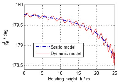
The orientation angles at the slack side and the tight side of pulley 6 are shown in Fig. 18 and Fig. 19 respectively based on both the dynamic and static model. It is observed that the orientation angle at slack side has big change relatively as the reeving way between pulley 6 and pulley 5 is inner common tangent and diverges more from vertical.
Fig. 15Linear velocity of pulley 6

Fig. 16Tensions of drum
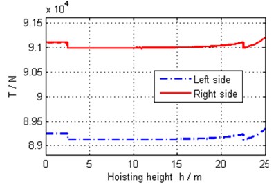
Fig. 17Orientation angles of tangency points on drum
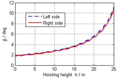
Fig. 18Orientation angle at slack side of pulley 6
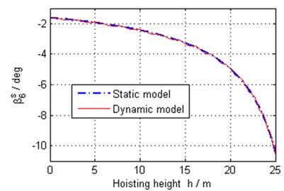
Fig. 19Orientation angle at tight side of pulley 6
8. Conclusions
While the polar crane in NPP works, the load trajectory is usually unavoidable to swing around the equilibrium path, which is not a vertical line strictly. To locate the load precisely, the mechanic design especially the layouts of the drum and pulleys as well as the reeving way of the rope branch should be considered. In this paper, a systematic method to analyze the trajectory of the hook block for polar crane in NPP is proposed, and some crucial parameters such as the rope tensions, the common tangent of spatial pulleys, and the angular speeds of pulleys are resolved. These parameters closely related to property and performance of rope-pulleys system should be considered in the designing of the crane that requires high precision to locate the load.
By analyzing the load trajectory, we can see that the swing amplitude of the load trajectory relates to the initial position and the trajectory deflections get bigger in general as load hoisting. The proposed method has a common adaptability and some parameters provided in this paper can be utilized as a reference for relevant designing of the hoisting system of crane.
References
-
Kim Y. S., Hong K. S., Sul S. K. Anti-sway control of container cranes: inclinometer, observer, and state feedback. International Journal of Control Automation and Systems, Vol. 2, Issue 4, 2004, p. 435-449.
-
Kim C. S., Hong K. S. Boundary control of container cranes from the perspective of controlling an axially moving string system. International Journal of Control, Automation and Systems, Vol. 7, Issue 3, 2009, p. 437-445.
-
Belunce A., Pandolfo V., Roozbahani H., et al. Novel control method for overhead crane’s load stability. Procedia Engineering, Vol. 106, 2015, p. 108-125.
-
Sun G., Kleeberger M., Liu J. Complete dynamic calculation of lattice mobile crane during hoisting motion. Mechanism and Machine Theory, Vol. 40, Issue 4, 2005, p. 447-466.
-
Park K. P., Cha J. H., Lee K. Y. Dynamic factor analysis considering elastic boom effects in heavy lifting operations. Ocean Engineering, Vol. 38, Issue 10, 2011, p. 1100-1113.
-
Pu H., Xie X., Liang G., et al. Analysis for dynamic characteristics in load-lifting system of the crane. Procedia Engineering, Vol. 16, Issue 1, 2011, p. 586-593.
-
Mcdonald B., Peyrot A. Analysis of cables suspended in sheaves. Journal of Structural Engineering, Vol. 114, Issue 3, 1988, p. 693-706.
-
Mcdonald B., Peyrot A. Sag-tension calculations valid for any line geometry. Journal of Structural Engineering, Vol. 116, Issue 116, 1990, p. 2374-2386.
-
Bruno D., Leonardi A. Nonlinear structural models in cableway transport systems 1. Simulation Practice and Theory, Vol. 7, Issue 3, 1999, p. 207-218.
-
Wei J., Xu W. Cable-pulley element to analyses pulley sliding on cable. Acta Mechanica Sinica, Vol. 37, Issue 3, 2005, p. 322-328, (in Chinese).
-
Aufaure M. A finite element of cable passing through a pulley. Computers and Structures, Vol. 46, Issue 5, 1993, p. 807-812.
-
Aufaure M. A three-node cable element ensuring the continuity of the horizontal tension; a clamp – cable element. Computers and Structures, Vol. 74, Issue 74, 2000, p. 243-251.
-
Zhou B., Accorsi M. L., Leonard J. W. Finite element formulation for modeling sliding cable elements. Computers and Structures, Vol. 82, Issues 2-3, 2004, p. 271-280.
-
Ju F., Choo Y. S. Dynamic analysis of tower cranes. Journal of Engineering Mechanics, Vol. 131, Issue 1, 2005, p. 88-96.
-
Wang J., Cao G., Wang Y., et al. A novel driving strategy for dynamic simulation of hoisting rope with time-varying length. International Journal of Modeling Simulation and Scientific Computing, 2013, https://doi.org/10.1142/S1793962313500098.
-
Hong D. W., Cipra R. J. A method for representing the configuration and analyzing the motion of complex cable-pulley system. Molecular Ecology Resources, Vol. 125, Issue 2, 2003, p. 7732-7741.
-
Lee K. H., Choo Y. S., Ju F. Finite element modelling of frictional slip in heavy lift sling systems. Computers and Structures, Vol. 81, Issue 30, 2003, p. 2673-2690.
-
Ju F., Choo Y. S. Super element approach to cable passing through multiple pulleys. International Journal of Solids and Structures, Vol. 42, Issue 11, 2005, p. 3533-3547.
-
Qi Z. Dynamics of Multibody Systems. Science Press, Beijing, 2008, p. 145-148, (in Chinese).
-
Zhang Q., Zhang R. Structure and Design of Engineering Crane. Chemical Industry Press, Beijing, 2008, p. 37-46, (in Chinese).
About this article
This work was supported by the National Natural Science Foundation of China, P. R. China (No. 11372057).

