Abstract
This paper established a computational model for the flow field of landing gear and extracted the velocity and vorticity distribution of flow field. A lot of shedding vortexes presented around the torque arm and pillar of landing gear and had the greatest impact on the flow field around the landing gear. Then, the aerodynamic noise of landing gear was measured in an anechoic chamber. The working noises of landing gear were more than background noises of landing gear. Their change trends were similar. Obvious peak frequencies presented at the front end of noise spectrum. In addition, peak frequencies increased with the increase of flow velocity. There were multiple peak frequencies on the curve of spectral characteristics. These frequencies were from pure sound in noises. Pure sound did not change with the change of flow velocity. The difference value of total sound pressure level of working noises and background noises was less than 10 dB. However, the difference value was bigger and bigger with the increase of flow velocity. When flow velocity was more than 50 m/s, background noises were over 10 dB lower than the total sound pressure level of working noises. Thus, it showed that the aerodynamic noise source of landing gear could be effectively recognized by experimental equipment. In addition, the total sound pressure level of aerodynamic noises of landing gear also increased with the increase of flow velocity and was directly proportional to the 6th power of flow velocity. The main noise source in experiments was dipole source. Finally, aerodynamic noises were obtained by AML model of landing gear, and compared with experimental results, showing consistent value and change trend. It showed that the computational model of noises was reliable. Based on the computational model of noises, this paper studied the contribution of pillar and torque arm of landing gear to radiation noises. Results showed that the pillar of landing gear was the main reason for radiation noises. In the future, pillar noises will be reduced through conducting structural design for the pillar of landing gear or applying sound package, further reducing radiation noises.
1. Introduction
Aircraft noises are composed of engine noises and airframe noises. Airframe noises contain high-lift equipment noises and landing gear noises. With the development of high-bypass engines and the progress of a series of engine noise reduction projects, engine noises will decrease to the same level and even a lower level than airframe noises. Then, airframe noises will be the main noise source of aircraft noises [1, 2]. When an aircraft parks and keeps its flap closed, landing gear noises can be 25 % of aircraft noises [3]. However, experimental research and numerical simulation become very difficult due to many factors including the complex geometric shape of landing gear, strong interaction with fluids [4, 5], wide-range acoustic band, wide spreading range, and relatively low energy. So far, the problem of landing gear noises has still been one of difficulties in studying airframe noises.
At present, methods of studying the aerodynamic noise of landing gear are mainly numerical computation and experimental test. The method of numerical computation refers to determining the distribution of unsteady pressure on the surface of landing gear based on fluid mechanics and obtaining noise distribution through acoustic software. Souliez [6] used CFD to compute the flow field of a simplified four-wheel landing gear and found that pillar system greatly affected landing gear noises, but the complexity of landing gear structure restricted further research. Li [7] found that the upstream pillar would have the phenomenon of vortex shedding through simulating the flow field of landing gear and additional noise would be caused due to the interaction between shedding vortexes and the flow field of downstream pillar. Spalart [8] found that the accuracy of computational results depended on the selected turbulence model through numerical simulation. Long [9] conducted numerical simulation analysis and experimental research on noises of the single-wheel landing gear of an aircraft, analyzed the generation mechanism, spectral characteristics and directivity of noises and evaluated the contribution of various parts to total noises, but he conducted serious simplified treatment for the landing gear. Li [10] completed the test on the aerodynamic noise of main landing gear of A340 in a wind tunnel, analyzed the generation mechanism of pure sound in noises and adopted different noise reduction methods to control noises. Dobrzynski [11] studied the noise characteristics of landing gear of A320 model and A340 model in a wind tunnel and reduced the noise of landing gear by 3 dB through installing a fairing. However, the wind tunnel blockage percentage of the model should not exceed 5 % in order to obtain the accurate measurement of aerodynamic noises in wind tunnel experimental research [12]. On the other hand, the measurement model of aerodynamic noises should be large as much as possible in order to be similar to the real shape, especially approximate Reynolds number, which was contradictory to the requirement of blockage percentage. To try to obtain experimental results approximating Reynolds number of the real shape, people adopted various measures to weaken wind tunnel blockage, like opening test sections and slotted walls [13]. Improvement of tunnel walls could not completely eliminate the interference and the remaining tunnel wall effect had to be amended [14].
Aiming at the problems of existing research, this paper combined with the experiment and numerical simulation of landing gear and studied the radiation noise and panel contribution of landing gear, which clearly made sense for reducing the radiation noise of landing gear.
2. Numerical computation of flow field of landing gear
Virtual. Lab direct boundary element module was adopted to compute the flow noise of landing gear. Firstly, the surface pressure fluctuation of landing gear was output based on unsteady numerical computation. Then, AML method was used to compute the aerodynamic noise of landing gear [15, 16]. AML acoustic-vibration coupling method was adopted to study the aerodynamic noise of landing gear: 1) Adopted Reynolds-average method to solve internal unsteady flow and transferred the wall pressure fluctuation data of landing gear to the wall meshes of structure; 2) Built AML model of landing gear in acoustic software; 3) Mapped the pressure fluctuation into the AML model and realized the coupling between flow field and structure to solve aerodynamic noises.
2.1. Mesh generation and flow field computation
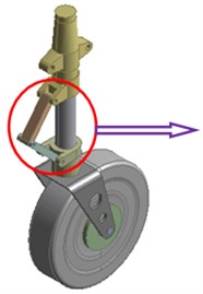
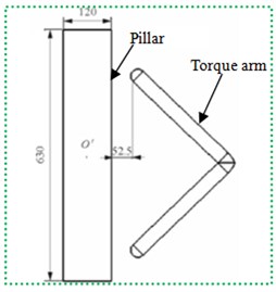
Fig. 1(a) presented the geometric model of landing gear. The model was made up of a torque arm, pillar and wheel. The torque arm was in front of the pillar. The round of interface of torque arm to the cross section of column was defined as the origin of coordinate O, as shown in Fig. 1(b). In the case of establishing computational model, some detail features which had little impact on flow field were neglected. The length and diameter of the pillar were 630 mm and 120 mm, respectively.
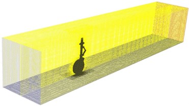
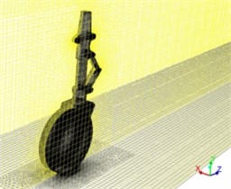
According to geometric model in Fig. 1, detail features were neglected to establish the mesh model of landing gear. Meanwhile, the computational domain for the flow field of landing gear was built according to the mesh model, as shown in Fig. 2. The rectangular region with 7D×20D×7D was selected as the computational domain. D was the height of pillar of landing gear. The origin was 7D away from the inlet, 13D away from the outlet and 3.5D away from left and right sides. The plane of inflow was set as velocity inlet. The outlet was set as pressure outlet. Other planes of computational domain and the surface of model were set as wall surfaces. Structured meshes were established according to model data. The distance between the mesh node of the first layer of boundary layer and wall surface was determined by a dimensionless parameter y+. In the numerical simulation in this paper, the distance between the mesh node of the first layer and the model was set as 0.01 mm. 20 layers were extended externally to generate the boundary layer according to the external expansion ratio of 1.1. Mesh size in the far field could be adjusted according to mesh quality. Finally, the number of structured meshes in the computational domain was 3.647.293 and the number of nodes was 3.794.621.
Fig. 1Geometric model of landing gear
a) Geometric model
b) Torque arm and pillar
Fig. 2Detailed description of computational domain for the flow field of landing gear
a) Computational domain for the flow field of landing gear
b) Meshes around the landing gear
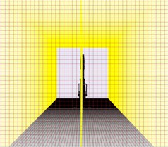
c) Symmetric plane of landing gear
Solver Fluent based on finite volume was used for solution. Unsteady flow was adopted to simulate the flow situation around the landing gear when the landing velocity of the aircraft was 50 m/s. Under the velocity, air around the model could be considered as incompressible gas. Its density was ρ= 1.225 kg/m3; dynamic viscosity was μ= 1.789×10⁻⁵ N·s/m2; kinematic viscosity was ν= 1.460×10⁻⁵ m2/s; Reynolds number was 4.1×10⁵; Mach number was 0.147. The computational time step was 1.3×10⁻⁴ s. Large eddy simulation was used for solution. The coupling between pressure and velocity adopted Simple algorithm. Space and time adopted second order accuracy.
2.2. Analysis on the computational results of flow field
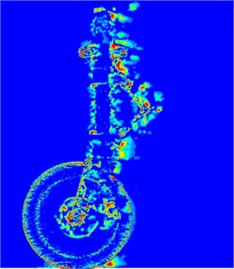
According to Nyquist Sampling Theories, the frequency of simulation analysis was 25000 Hz. The selected sample length was 4096. The resolution ratio of frequency-domain analysis was 12.2 Hz. When overlapping ratio was 50 %, fast Fourier transform was conducted for 5 samples to obtain overall average. The purpose of overall average was to reduce the random noise error of signals. Due to the computational time, the number of samples adopted by simulation was less than that collected by experiments. In the process of signal processing, Hanning window was added in the case of signal processing and the impact of Hanning window on the density amplitude of pressure spectrum was modified in order to reduce leakage error in the frequency domain because of truncated signals in the time domain. According to the established model and set parameters, the flow velocity and vorticity distribution of fluids around the landing gear were obtained, as shown in Fig. 3 and Fig. 4. It could be seen from Fig. 3 that fluid firstly acted on the pillar of landing gear and the flow velocity of fluid around the torque arm of landing gear was larger than that in other positions. Fig. 4 showed that fluid around the landing gear had many shedding vortexes.
Fig. 3Velocity distribution of fluids around the landing gear
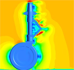
a)t= 0.1 s
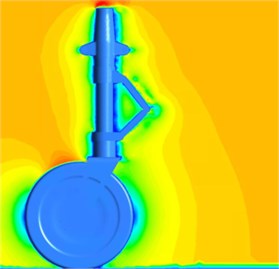
b)t= 0.2 s
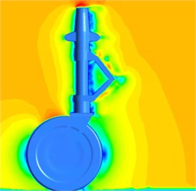
c)t= 0.3 s
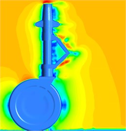
d)t= 0.4 s
3. Experiments of the flow noise of landing gear
To avoid the impact of the environment on experimental results, experiments were conducted in an anechoic chamber. As shown in Fig. 5, the installation method of experimental landing gear kept the same with that of numerical simulation. Landing gear was installed by clip on the pillar and the pillar was fixed on the ground by linear clip. To reduce the disturbance of pillar and clip on signals, pillar, clip and other objects before experiments were parceled by sound-absorbing sponge. The volume of the laboratory was 125 m3. Experimental frequency was 0 Hz-5000 Hz. The experimental landing gear was installed on the experimental platform of open wind tunnel. The size of outlet of the wind tunnel was 270 mm×330 mm. Turbulence in the center of inflow was less than 1 %. The microphone adopted a 1/2-inch capacitance sensor. The diameter of the microphone was 13.2 mm. Dynamic test range was 30 dB-140 dB. The position of sound source was defined as the origin of coordinate. X-axis was in the direction of airflow; z-axis was in the direction vertical to the ground; y-axis was determined by left-hand rule. The microphone was on one side and top of the landing gear. The acquisition equipment of experimental data was PAK vibration and noise test system produced by BBM Company. Data acquisition equipment could collect the data of multichannel vibration or acoustic signals and cooperate with PAK software in computer to transmit, save and process data real-timely and present results.
Fig. 4Vorticity distribution of fluids around the landing gear
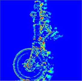
a)t= 0.1 s
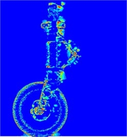
b)t= 0.2 s
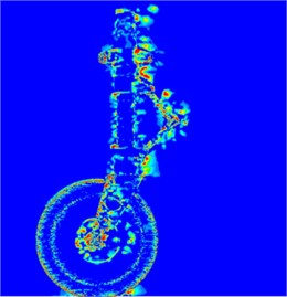
c)t= 0.3 s
d)t= 0.4 s
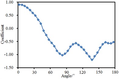
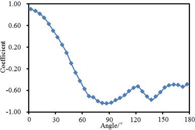
Through experiments on aerodynamic noises, the pressure coefficient in the symmetric plane of landing gear could be measured. The position facing inflow was 0° and the position back to inflow was 180°. Fig. 6 showed the pressure coefficient of landing gear close to the wing and ground side. As shown from the figure, pressure coefficient gradually decreased with the increase of angle before 90°. Between 90° and 120°, pressure coefficient showed an obvious peak value. The peak value of pressure coefficient was –0.57 on the ground side and –0.53 on the wing side. Between 120° and 150°, pressure coefficient showed an obvious valley value. The valley value of pressure coefficient was –1.2 on the ground side and –0.78 on the wing side.
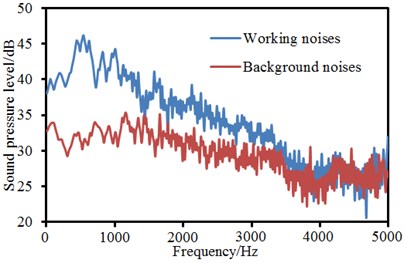
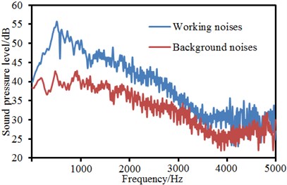
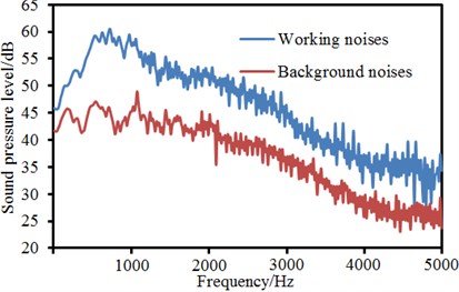
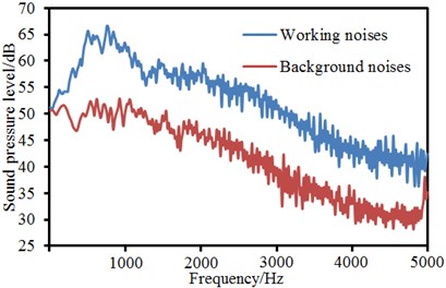
To study the aerodynamic noise of landing gear under different fluid velocities, wind velocity was set as 30 m/s, 40 m/s, 50 m/s, 60 m/s, 70 m/s and 80 m/s respectively in the wind tunnel to measure the working noise of landing gear. In addition, wind velocity was set as 30 m/s, 40 m/s, 50 m/s, 60 m/s, 70 m/s and 80 m/s respectively to measure the background noise of experiments after the landing gear was removed. Observation point 5 was taken as an example. A comparison between working noises and background noises under all wind velocities was made, as shown in Fig. 7. The noise generation mechanism of landing gear and its noise characteristics were analyzed. As shown from Fig. 7, working noises of landing gear were more than background noises. Their change trends were similar. There were obvious peak frequencies at the front end of noise spectrum. In addition, peak frequency increased with the increase of inflow velocity. Additionally, multiple peak frequencies presented on the curve of spectral characteristics. These frequencies were from pure sound in noises. The pure sound did not change with the change of inflow velocity. Fig. 8 showed a comparison between working noises under different wind velocities. It could be seen from the figure that working noises of landing gear under different wind velocities were similar.
Fig. 5Experimental process of the aerodynamic noise of landing gear
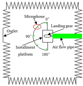
Fig. 6Experimental pressure coefficient of landing gear
a) Ground side
b) Wing side
Table 1 presented a comparison of total sound pressure level of working noises and background noises under all velocities. As shown from Table 1, the difference value of total sound pressure level of working condition and background noises was less than 10 dB when inflow velocity was 30 m/s and 40 m/s. However, the difference value became bigger and bigger with the increase of inflow velocity. When inflow velocity was more than 50 m/s, the difference value of total sound pressure level of working condition and background noises was more than 10 dB. Thus, it showed that the aerodynamic noise source of experimental landing gear could be effectively recognized by experimental equipment. From Table 1, it could also be seen that total sound pressure level increased with the increase of inflow velocity. In addition, sound power was directly proportional to the 6th power of inflow velocity. According to Lighthill acoustic theories, the total sound powers of monopole, dipole and quadrupole sources were directly proportional to the 4th, 6th and 8th power of inflow. Results showed that the main noise source of aerodynamic noises in experiments was dipole source.
Fig. 7Working noises and background noises of landing gear under different velocities
a) Velocity = 30 m/s
b) Velocity = 40 m/s
c) Velocity = 50 m/s
d) Velocity = 60 m/s
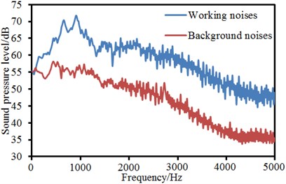
e) Velocity = 70 m/s
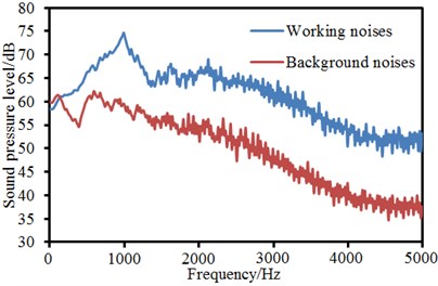
f) Velocity = 80 m/s
Fig. 8Comparison of working noises of landing gear under different velocities
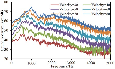
Table 1A comparison of total sound pressure levels under different velocities
Velocity / (m/s) | Sound pressure level / dB | Errors / dB | |
Working noises | Background noises | ||
30 | 61.71 | 54.63 | 7.08 |
40 | 68.59 | 60.01 | 8.58 |
50 | 75.55 | 64.79 | 10.76 |
60 | 84.21 | 72.16 | 12.05 |
70 | 89.90 | 75.77 | 14.13 |
80 | 95.67 | 80.70 | 14.97 |
4. Numerical computation of aerodynamic noises of landing gear
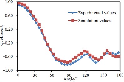
Fig. 6 showed the experimental pressure coefficient of landing gear and compared it with the pressure coefficient of numerical computation, as shown in Fig. 9. The experimental results were very similar to results of numerical computation. Pressure coefficients of peak and valley values were approximate. It indicated that the computational model of flow field in this paper was reliable.
Fig. 9Comparison of pressure coefficients of landing gear between experiment and simulation
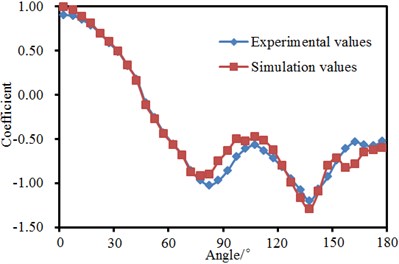
a) Ground side
b) Wing side
Fig. 10Computational model for the aerodynamic noise of landing gear
a) AML model
b) Field point model
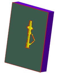
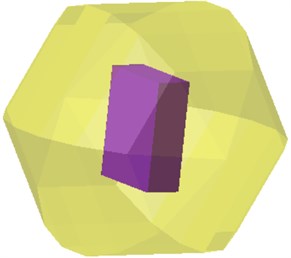
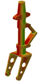
Studying the aerodynamic noise of landing gear only by means of experiments would increase cost and reduce efficiency. Therefore, this paper attempted to use AML coupling method to compute the aerodynamic noise of landing gear. Results of flow field were imported into Virtual. Lab. According to the structural model of landing gear, the coupling surface of landing gear with AML model was built, as shown in Fig. 10(a). AML coupling surface was coupled with the flow field results of landing gear. In this way, flow field results could be mapped to AML coupling surface. The acoustic meshes of landing gear could obtain all flow field results and thus compute the acoustic-vibration coupling of landing gear. After AML model of landing gear was built, experimental field points in Fig. 5 were taken as reference model to build the field point model of aerodynamic noises of landing gear, as shown in Fig. 10(b). Finally, the numerical computation model for the aerodynamic noise of the landing gear contained 102.452 elements and 128.745 nodes. The computed upper frequency limit was set as 5000 Hz and step length was 20 Hz. In this way, contours for the aerodynamic noise of landing gear could be obtained, as shown in Fig. 11. It could be seen from Fig. 11 that the aerodynamic noise of landing gear was mainly distributed in the pillar and torque arm.
Experimental and numerical simulation results of aerodynamic noise at field point R1 and R2 in Fig. 5 and Fig. 10(b) were extracted, as shown in Fig. 12. As shown from Fig. 12, the aerodynamic noise of the landing gear was similar between numerical simulation and experimental results. The maximum error was no more than 4 dB. Simulation and experiments were consistent in peak frequency, which indicated that the computational model for the aerodynamic noise of landing gear in this paper was reliable. The aerodynamic noise of landing gear under different velocities was also computed numerically and one-third octave was processed, as shown in Fig. 13. R1 was at the upper part of landing gear; R2 was at the top of landing gear; R3 was at the lower part of landing gear. As shown from Fig. 13, the aerodynamic noise of landing gear gradually increased with the increase of wind velocity.
Fig. 11Contours for the aerodynamic noise of landing gear
a) 500 Hz
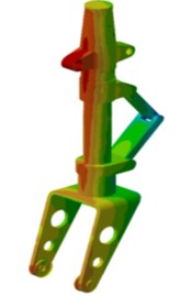
b) 1000 Hz
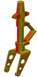
c) 1500 Hz
Fig. 12Comparison of radiation noises of landing gear between experiments and simulation
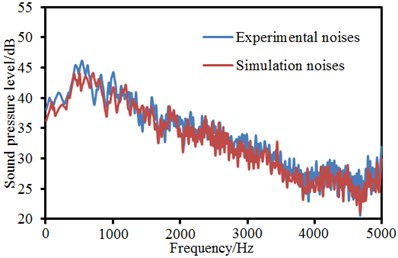
a) Field point R1
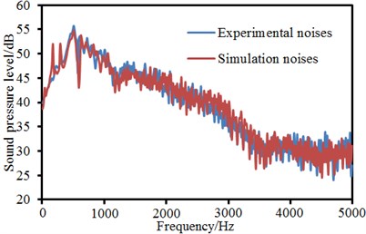
b) Field point R2
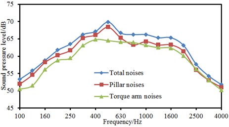
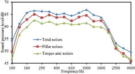
Parts including pillar and torque arm of landing gear were divided into different panels to analyze the panel contribution of aerodynamic noises of landing gear, as shown in Fig. 14. As shown from Fig. 14, the pillar noises of landing gear obviously made greater contributions to total noises than torque arm noises when the analyzed frequency was lower than 1600 Hz. When the analyzed frequency was more than 1600 Hz, pillar noises made similar contribution with torque arm noises. In addition, peak value on the sound pressure level curve of total noises of landing gear was caused by pillar. Therefore, it showed that the pillar of landing gear had the biggest impact on the radiation noise of landing gear. In the future work, pillar noises could be reduced through conducting structural design for the pillar of landing gear or applying sound package.
Fig. 13Numerical computation results for the noise of landing gear under different velocities
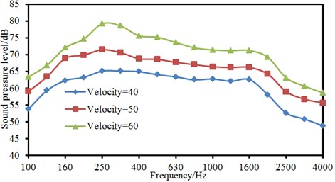
a) Field point R1
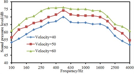
b) Field point R2
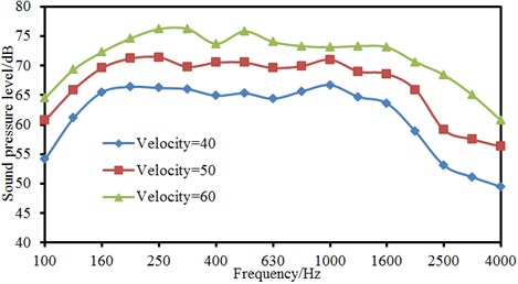
c) Field point R3
Fig. 14Analysis on the panel contribution of aerodynamic noises of landing gear
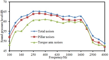
a) Field point R1
b) Field point R2
c) Field point R3
5. Conclusions
This paper established a computational model for the flow field of landing gear and extracted the velocity and vorticity distribution of flow field. A lot of shedding vortexes presented around the torque arm and pillar of landing gear and had the greatest impact on the flow field around the landing gear. Then, the aerodynamic noise of landing gear was measured in an anechoic chamber. The working noises of landing gear were more than background noises of landing gear. Their change trends were similar. Obvious peak frequencies presented at the front end of noise spectrum. In addition, peak frequencies increased with the increase of flow velocity. There were multiple peak frequencies on the curve of spectral characteristics. These frequencies were from pure sound in noises. Pure sound did not change with the change of flow velocity. The difference value of total sound pressure level of working noises and background noises was less than 10 dB. However, the difference value was bigger and bigger with the increase of flow velocity. When flow velocity was more than 50 m/s, background noises were over 10 dB lower than the total sound pressure level of working noises. Thus, it showed that the aerodynamic noise source of landing gear could be effectively recognized by experimental equipment. In addition, the total sound pressure level of aerodynamic noises of landing gear also increased with the increase of flow velocity and was directly proportional to the 6th power of flow velocity. The main noise source in experiments was dipole source. Finally, aerodynamic noises were obtained by AML model of landing gear, and compared with experimental results, showing consistent value and change trend. It showed that the computational model of noises was reliable. Based on the computational model of noises, this paper studied the contribution of pillar and torque arm of landing gear to radiation noises. Results showed that the pillar of landing gear was the main reason for radiation noises. In the future, pillar noises will be reduced through conducting structural design for the pillar of landing gear or applying sound package, further reducing radiation noises.
References
-
Casalino D., Diozzi F., Sannino R. Aircraft noise reduction technologies: a bibliographic review. Aerospace Science and Technology, Vol. 12, Issue 1, 2008, p. 1-17.
-
Dobrznsi W. Almost 40 years of airframe noise research: what did we achieve? Journal of Aircraft, Vol. 47, Issue 2, 2010, p. 353-367.
-
Monclar P. Technology programs for landing gear systems. AIAA/CEAS International Air and Space Symposium and Exposition, Dayton, 2003.
-
Boorsma K., Zhang X., Molin N. Landing gear noise control using perforated fairing. Acta Mechanica Sinica, Vol. 26, Issue 1, 2010, p. 159-174.
-
Nie H., Wei X. H. Key technologies for landing gear of large civil aircrafts. Journal of Nanjing University of Aeronautics and Astronautics, Vol. 40, Issue 4, 2008, p. 427-432.
-
Souliez F. J., Long L. N., Morris P. J. Landing gear aerodynamic noise prediction using unstructured grids. International Journal of Aeroacoustics, Vol. 2, 2002, p. 115-135.
-
Li F., Khorrami M. R., Malik M. R. Unsteady simulation of a landing-gear flow field. American Institute of Aeronautics and Astronautics, 8th AIAA/CEAS Aeroacoustics Conference and Exhibit, 2002.
-
Spalart P. R. Detached-eddy simulation. Fluid Mechanics, Vol. 41, 2009, p. 181-202.
-
Long S. L., Nie H., Xue C. J. Simulation and experiment on aeroacoustic noise characteristics of aircraft landing gear. Acta Aeronautica et Astronautica Sinica, Vol. 33, Issue 6, 2012, p. 1002-1013.
-
Li Y., Smith M. G., Zhang X. Identification and attenuation a tonal-noise source on an aircraft’s landing gear. Journal of Aircraft, Vol. 47, Issue 3, 2010, p. 796-804.
-
Dobrzynski W., Chow L. C., Smith M. Experimental assessment of low noise landing gear component design. International Journal of Aeroacoustics, Vol. 9, Issue 6, 2010, p. 763-786.
-
Cheng H. M. Interference and Correction on Wind Tunnel Testing. National Defence Industry Press, Beijing, 2003.
-
Bishop M., Yarusevych S. Mitigating blockage effects on flow over a circular cylinder in an adaptive-wall wind tunnel. Journal of Fluids Engineering, Vol. 133, Issue 8, 2011, p. 081101.
-
Garbaruk A., Shur M., Strelets M., et al. Numerical study of wind-tunnel walls effects on transonic airfoil flow. AIAA Journal, Vol. 41, Issue 6, 2003, p. 1046-1054.
-
Miccoli G., Nizzoli T. Arrayable loudspeaker horn BEM/FMBEM and FEM/AML modeling and analysis. Proceedings of the 20th International Congress on Sound and Vibration, 2013.
-
Sgard F., Brummund M., Viallet G., et al. Prediction of airborne and structure borne sound transmission through hearing protectors using FEM. Proceedings of Internoise, 2014.
About this article
Yaoming Zhou have completed the writing and translation, Yao-long Liu proposed the idea of this paper, experimental test was completed by Shao-wei Li, and the rest authors have checked and submitted this paper.

