Abstract
Numerical simulation and wind tunnel experiment were conducted for flow field and flow noise characteristics of four-wheel landing gear. Under the landing speed, large eddy simulation method was applied to simulate the unsteady turbulent flow field around the landing gear. In addition, vortex-acoustic theory was also employed to compute the intensity and position of sound source, and integral method of FW-H equation was used to solve the sound field generated from different components and their combinations, analyze the noise generation mechanism, spectral characteristics and far-field directivity. Meanwhile, the contribution of each component to the total noise was assessed. The aerodynamic acoustic experiment was conducted for landing gear in the wind tunnel, and a microphone was applied to measure and obtain the spectral characteristics of noise, which was compared with the numerical computation result. As shown from the result, a good agreement was found between the experimental and numerical results. Besides, it was shown from the simulation result that small parts ignored in the computational sound field played a greater impact on prediction result of noise, especially high-frequency noise. As shown from landing gear vorticity and sound pressure distribution, sound source was mainly distributed in the solid surface of various components for the landing gear. Additionally, sound source was also occurred in the vortex shedding positions behind each component. Greater energy and density of the sound source were found in the gap formed between tire and bogie and in the pillar stairs. The tire noise showed maximum contribution to the total noise, followed by the bogie noise, while the pillar noise was minimal. The total noise spectrum was closest to the tire noise spectrum.
1. Introduction
The airframe noise in landing stage was mainly from the landing gear and high lift devices [1, 2]. However, the landing gear noise occupied 25 % of the total aircraft noise when the engine was stopped and the wing was folded [3]. Nevertheless, numerical simulation and experimental research of landing gear noise was difficult due to the complex geometry of landing gear, its strong interaction with surrounding fluids [4-6], as well as wide acoustic band range, extensive spread range and relatively low energy and other factors. The landing gear noise problem has still been one of the difficulties in airframe noise studies so far.
Currently, a lot of researches have been conducted in the aspect of aerodynamic noise regarding the landing gear. Kourbatski [7] presented a computational investigation of the problem of unsteady flow past a rudimentary four-wheel landing gear configuration and associated far-field noise radiation, and numerical values of pressure spectra at selected location on the landing gear were compared with experimental data. Long [8] applied separate vortex method to simulate unsteady turbulent flow field on the basis of front landing gear model of the airplane, extracted the intensity and distribution information of sound source, and solved sound field result by the integral method of FW-H equation. In her conclusion, the greatest impact on far-field radiation noise was played by the tire noise of the landing gear, followed by bogie and pillar. The far-field noise produced by a Rudimentary Landing Gear (RLG) was investigated using Delayed Detached Eddy Simulation (DDES) coupled with a Ffowcs-Williams Hawkings (FWH) integral [9]. Computational results are presented for the RLG geometry using three unstructured grids of quasi-nested refinement. DDES has the potential to become a viable tool for evaluating low noise gear designs during the early design phases before wind tunnel and flight testing have commenced. Liu [10] computed the landing-gear noise using high-order finite difference schemes, and both aerodynamic and aero-acoustic results are compared to wind tunnel measurements and are found to be in good agreement. For Dobrzynski [11], a wind tunnel test was conducted for front landing gear and main landing gear of aircraft A320, the noise source positions was obtained on the basis of microphone array, and the low-noise landing gear was designed on the former basis. Spalart [12] computed the far-field and near-field noise of the landing gear numerically, studied the noise spectrum characteristics of landing gear under different yaw angles, and found that yaw angle affected the landing gear noise quite seriously. The mentioned researches on the landing gear are not deep enough, and the analysis of the components was not conducted. In addition, the research was only conducted based on experiment or simulation separately.
Large eddy simulation was applied in the paper to calculate the flow filed numerically. Then, the acoustic field characteristics on the surface of the landing gear were studied on the basis of flow field results and verified through experiments. Finally, the integral method was employed to study the impact of different components of landing gear on the far-field noise.
2. Theoretical backgrounds
2.1. Flow field calculation
The incompressible viscous flow field could be applied in the external flow field of the landing gear, whose basic equation was as follows:
wherein: ui and uj are flow field speeds around the landing gear, xi and xj are components of the coordinate, ρ represents the air density, p means pressure and μ expresses the aerodynamic viscosity.
Large eddy simulation equations were stillN-S equation of incompressible fluid, and large-scale speed in LES was the filtering speed, which was defined as follows:
wherein: G(x,x',Δ) represents the filter function, which is applied to calibrate large eddy and filter small eddy. Δ means the size of the filter grid. It is assumed that the filtration process can be exchanged with the process of derivation, which can be applied in N-S equation of incompressible viscous fluid. Regardless of G form, the following equation can be always obtained:
wherein: ˉτij=-(¯uiuj-¯ui¯uj) is SGS Renolds Stress, which is a new unknown quantity that needs modeling.
For making equations closed, it is assumed that SGS stress can be expressed as the following equation in accordance with basic SGS model of Smagorinsky:
wherein: μi represents the viscosity coefficient of the subgrid turbulence and ˉSij means the strain tensor component under the solving scale. ˉSij is defined as the following equation:
As LES could only make transient calculation with a higher requirement for the initial flow field, the calculation of steady flow field was firstly solved by the application of standard k-ε turbulence model, whose equations were shown below:
wherein: k represents the turbulent kinetic energy, ε is the turbulent dissipation rate, μt is the turbulent viscosity coefficient, μt=Cμρk2/ε, and Cμ is the constant of turbulence. Under normal circumstances, Cμ= 0.09. C1, C2, σk, and σε are empirical constants. C1= 1.47, C2= 1.92, σk= 1.0 and σε= 1.33 were extracted for the calculation in the paper.
2.2. Computation of sound field
Sound field simulation was based on FW-H equation, as shown in Eq. (10). The sound radiation source was represented by the right three terms in FW-H equation, wherein the first term represented the turbulent stress of the fluid itself, with quadrupole characteristics; the second term expressed the divergence of unsteady force exerted on certain interfaces, with dipole characteristics; and the third term was the unsteady mass flow entering into the fluid, with monopole characteristics:
+∂∂t{[ρ0υn+ρ(un-υn)]δ(f)},
wherein: a0 is the speed of sound, p' is the fluctuating sound pressure, Tij is the stress tensor of Lighthill, and Pij is a stress tensor of the compressible fluid. ui is the velocity component of fluid in the direction of xi, un is the normal velocity of fluid on the surface of f=0. υn is the normal component of velocity on the object surface. H(f) expresses generalized function of Heaviside and δ(f) is nowhere continuous function. Without any volume integral, all sound sources within the integral plates can be calculated by FW-H equation. The part surface was defined as the integral plate in the simulation herein.
3. Computation of noise on landing gear surface
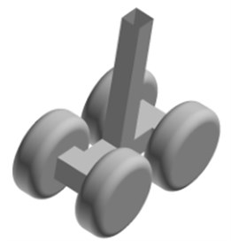
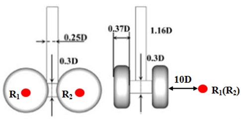
Great difficulties for geometry modeling, mesh generation and aerodynamic noise computation would be caused by the details in the landing gear. Therefore, the details of the simulation model needed to be simplified under the premise of the remained main features of the sound field, as shown in Fig. 1. Such simplification retained the most structures of the real landing gear and only leaved out small components, but it would not have a significant influence on the calculation result. At present, the reported models of the landing gear were basically shown in Fig. 1. They could be considered as standard models. For instance, the model of the landing gear based on simplification in literature [7-13] numerically computed the aerodynamic noise of the landing gear and obtained some meaningful conclusions. The tire diameter of the landing gear was D. The axial distance of front and rear tires was 1.16D, pillar width and length were both 0.25D, distance between tires was 0.88D, bogie height and width were both 0.3D, and tire width was 0.37D. On the basis of the sizes, the established three-dimensional model of the landing gear was shown in Fig. 2. The sizes of four wheels of the landing gear were remained consistent and symmetrical with respect to the bogie.
Fig. 1Sizes of main parts of landing gear
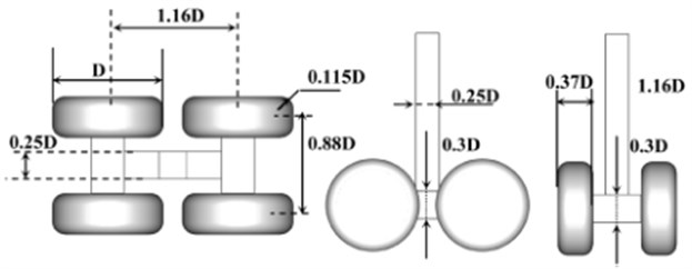
Fig. 2Geometric model of landing gear
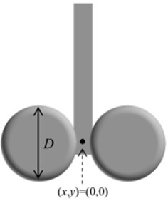
In the calculation process of flow field for the landing gear, the calculation domain needed to be divided firstly. The pillar axis was 3.5D away from the entrance and 6.5D away from the exit. The incoming flow surface was defined as the speed inlet, the entrance plane was defined as the free outlet, and other surfaces and model surfaces were all defined as the wall. The established three-dimensional solid model was converted to the common output format, and then imported into the mesh generation software GRIDGEN. According to the database of the geometric model, the structured grid was created as shown in Fig. 3(a). A total of 1,458,961 hexahedral elements were included in the computational domain. As shown in Fig. 2, the tire and bogie of the landing gear were rigidly connected. 4 tires were connected with both sides of the bogie. In the process of generating meshes, mesh generation was firstly conducted for the tire. Mesh size was 2 mm. Then, mesh generation was conducted for the bogie. Mesh size was also 2 mm. Finally, the tire and bogie were rigidly connected to form the model as shown in Fig. 3(b).
Fig. 3Computational domain and local grid of landing gear
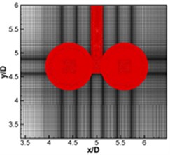
a) Computational domain of landing gear
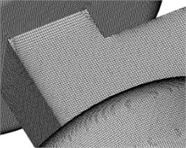
b) Local elements
Based on the aerodynamic characteristic of the landing gear, the SPL contours can be obtained. SPL contours of the landing gear at 600 Hz and 800 Hz were extracted as shown in Fig. 4, which showed that the sound pressure at 600 Hz was significantly greater than that at 800 Hz.
Fig. 4SPL contours of landing gear
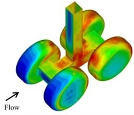
a) 600 Hz
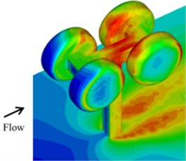
b) 600 Hz
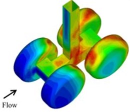
c) 800 Hz
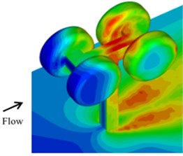
d) 800 Hz
4. Experimental verification for numerical calculation results
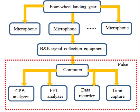
Wind tunnel test was conducted for the landing gear to verify the accuracy concerning numerical simulation of the landing gear noise, as shown in Fig. 5. The landing gear was fixed in the wind tunnel with the certain amount of incoming flow applied oppositely. The full-size model of the landing gear in an airplane was used as the test sample, which was mounted on the wind tunnel ground. Microphone was placed near the landing gear to obtain the sound pressure signals, and the experimental time was 2 s, and each test was conducted for three times. Finally, the average value was the final result. The experimental process was shown in Fig. 6. When the signal was obtained, it was imported into the computer. Then, the signal was processed by pulse software to the sound pressure level.
Fig. 5Wind tunnel tests of landing gear
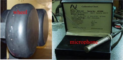
Fig. 6The experimental process
The test result was compared with the numerical simulation result, as shown in Fig. 7. It was indicated the basically consistent overall trend between the simulation and experimental results, as well as certain differences existing in terms of values.
Fig. 7SPL comparison between simulation and experiment
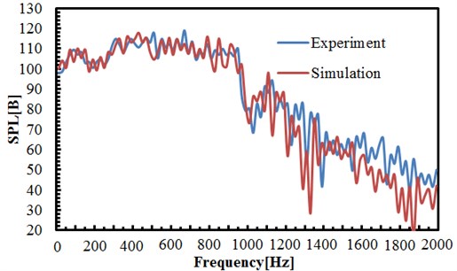
The simulation model produced its sound through the interaction of the uniform incoming flow and airflow. However, since the wind-ward area of the model had the ratio of 23 % against the opening test of the wind tunnel in the experiment, the experimental flow field was of greater difference with the uniform incoming flow, and the experimental test conditions was considerably different from the actual landing condition, which was therefore an important source of errors existing in the simulation and experimental measurement results. Some model details were ignored in the geometrical modeling of the simulation model, but they had mainly generated high-frequency sound waves, thus causing errors in the high frequency band. Generally speaking, the landing gear noise calculated through such model was reliable.
5. Analysis of noise characteristics for landing gear components
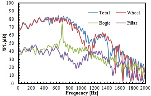
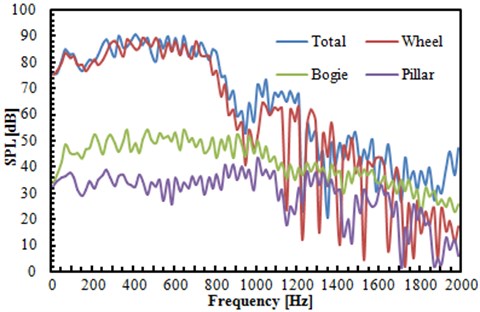
Solid surfaces of bogie, tires, pillar and the whole landing gear were selected as the integral surface, as shown in Fig. 8. The noise generated by components and the entire landing gear model was calculated in the far field. The position of R1 and R2 was as shown in Fig. 9. They were 10D away from the tire on the right-hand side horizontally and faced the center of front and back tires directly. The measurement points R1 and R2 in the far field were taken as the example to illustrate the noise characteristics of various components as well as the contribution of various components to the total noise. The spectral simulation curves of each component at two points were shown in Fig. 10.
Fig. 8Integral surface of various components for landing gear
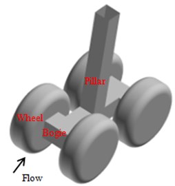
Fig. 9Position of the observation point R1 and R2
In the lateral position R1, the narrow-band peak was appeared in the spectral curve of bogie at about 696 Hz, with the peak change of 20 dB. In the position R2, the characteristics of broadband noise were presented in the spectrum of bogie, without apparent narrow-band peak value. As shown from the simulation result, the sound source with the frequency of about 696 Hz was included in the bogie noise, including certain directivity. As shown from the sound source localization, strong sound source was presented in the gap between bogie and tire, indicating that the sound source in the bogie was generated from the cavity formed by the fluid passing through the gap between bogie and tire, which could also be seen in Fig. 4. Due to the reflection of tire surface on the cavity noise, the sound waves generated from the sound source was mainly spread towards both sides of the tire. Therefore, in the lateral position, strong energy and apparent peak of noise can be recognized in the narrow-band peak; while in the position right behind landing gear, small energy and unapparent peak of noise were found in the narrow-band peak. When the analyzed frequency changed from 1100 Hz to 1800 Hz, SPL curve of various components presented a large fluctuation. It was mainly because the analyzed frequency band was high frequency for the landing gear. The modal density of the landing gear at the high frequency band was relatively higher. Various components had serious resonance under the action of fluid, which was manifested as a large fluctuation in SPL curve.
Fig. 10SPL comparison regarding different integral surfaces in points R1 and R2
a) SPL comparison regarding different integral surfaces in point R1
b) SPL comparison regarding different integral surfaces of point R2
As shown from Fig. 10, the total noise frequency was closest to tire noise frequency of the model. Firstly, SPL of each component was transformed into sound pressure. Secondly, the average sound pressure of various components at observation points was obtained and average SPL was further computed. The average noise of various components generated at two points was listed in Table 1. It was seen that the tire noise had the maximum contribution to the aerodynamic noise of the entire model, followed by bogie noise contribution, but pillar noise made lowest contribution to the noise of the entire model.
Table 1Average SPL of various components at points R1 and R2
Point | Pillar | Bogie | Wheel | Total |
R1 | 35.61 | 38.23 | 73.33 | 74.42 |
R2 | 32.35 | 40.44 | 72.19 | 73.21 |
6. Conclusions
The near-field and far-field noises of the landing gear were studied based on wind tunnel test and numerical simulation. Small components of simulation model had a significant influence on the prediction result of high-frequency noises. However, the computational result of the numerical model was basically the same with the experimental result. The flow noise of the landing gear could be effectively computed. In addition, it could be seen from sound pressure distribution of the landing gear that strong sound source was mainly distributed in the solid surface of various components of the landing gear. A lot of sound source was also in the position of vortex shedding at the back of various components. The energy and density of sound source were relatively larger at the position of a gap formed by the tire and wheel fork and on the steps of the bogie. Finally, an analysis was conducted on the contribution of various components of the landing gear. Results found that the tire noise of the landing gear made the great contribution to the overall noise, followed by the noise of wheel fork. Bogie noises made the smallest contribution to the overall noise. The frequency spectrum of the overall noise was the closest to that of tire noises. Therefore, the subsequent studies will take optimization measures to reduce the aerodynamic radiation noise, including adopting sound package, new materials or the redesign of structures. The actual structure of the landing gear could be redesigned through these studies to effectively improve the radiation noise brought by the landing gear when airplanes were in the process of landing and take-off, which had a great application value to aeronautical engineering.
References
-
Qiao W. Y., Xu K. F., Wu Z. W. Noise radiation of large-scale commercial aircraft in take-off and landing. Acta Aeronautica et Astronautica Sinica, Vol. 29, Issue 3, 2008, p. 534-541.
-
Dobrzynski W. Almost 40 years of airframe noise research: what did we achieve. Journal of Aircraft, Vol. 47, Issue 2, 2010, p. 353-367.
-
Monclar P. Technology programs for landing gear systems. AIAA/CEAS International Air and Space Symposium and Exposition, 2003, p. 1-9.
-
Boorsma K., Zhang X., Molin N. Landing gear noise control using perforated fairings. Acta Mechanical Sinica, Vol. 26, Issue 1, 2010, p. 159-174.
-
Nie H., Wei X. H. Key technologies for landing gear of large civil aircrafts. Journal of Nanjing University of Aeronautics and Astronautics, Vol. 40, Issue 4, 2008, p. 427-432.
-
Lazos B. S. Mean flow features around the inline wheels of four-wheel landing gear. AIAA Journal, Vol. 40, Issue 2, 2002, p. 193-198.
-
Kourbatski K. A., Viti V., Menter F., et al. Rudimentary landing gear noise predictions using scale-resolving simulations: Part 1 – Incompressible approach. AIAA Paper, Vol. 463, 2013.
-
Long S. L., Nie H., Xue C. J. Simulation and experiment on aero-acoustic noise characteristics of aircraft landing gear. Acta Aeronautica et Astronautica Sinica, Vol. 33, Issue 6, 2012, p. 1002-1013.
-
Langtry R. B., Larssen J. V., Winkler C. M., et al. DDES and acoustic prediction of rudimentary landing gear experiment using unstructured finite volume methods. Flow, Turbulence and Combustion, Vol. 91, Issue 3, 2013, p. 717-745.
-
Liu W., Kim J. W., Zhang X., et al. Landing-gear noise prediction using high-order finite difference schemes. Journal of Sound and Vibration, Vol. 332, Issue 14, 2013, p. 3517-3534.
-
Dobrzynski W., Roland E., Pott-Pollenske M. Research at DLR towards airframe noise prediction and reduction. Aerospace Science and Technology, Vol. 12, Issue 1, 2008, p. 80-90.
-
Spalart P. R., Shur M. L., Strelets M. K., et al. Initial noise predictions for rudimentary landing gear. Journal of Sound and Vibration, Vol. 330, Issue 17, 2011, p. 4180-4195.
-
Spalart P. R., Shur M. L., Strelets M. K., et al. Reprint of: towards noise prediction for rudimentary landing gear. Procedia IUTAM, Vol. 1, 2010, p. 283-292.
-
Li Y., Smith M., Zhang X. Measurement and control of aircraft landing gear broadband noise. Aerospace Science and Technology, Vol. 23, Issue 1, 2012, p. 213-223.

