Abstract
Since the moving element method (MEM) is an elegant method for solving problems involving moving loads. This paper extends the moving element method to the dynamic response of the water-saturated subgrade surface layer under a high-speed train. The track model is described as the Euler beam to simulate the rail, concrete slab layer and elastic medium to simulate the concrete base layer. The water-saturated subgrade surface layer is characterized by Biot’s dynamic poroelastic theory, and the other subgrade components are regarded as elastic medium. The governing equations are formulated in a coordinate system traveling at a constant velocity, and the associated finite element formulation in a moving frame of reference is derived. The proposed computational scheme is applied to investigate the dynamic characteristics of the water-saturated subgrade surface layer subjected to the moving train load. The effects of various key parameters including the train velocity, permeability, drainage boundary, elastic modulus and rail irregularity on hydro-mechanical response of the saturated subgrade surface layer are carefully analyzed.
1. Introduction
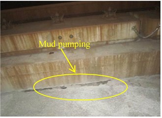
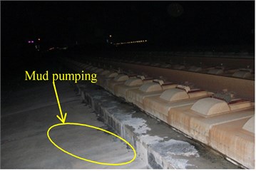
The dynamic responses of road structures induced by moving vehicle loads have drawn a great interest in a number of engineering fields such as civil engineering, transportation engineering and environmental engineering. Recently the high-speed rail development has entered a rapid phase due to China’s enormous investments in its high-speed rail network. During the service life of high-speed railways, the subgrade will be exposed to frequent intense rainfalls and groundwater-level variations, due to the poor drainage conditions, the water content in the subgrade will also change greatly from the optimum water content to the saturation status during the wet season [1]. The water transport is important since it strongly affects the mechanical behavior of subgrade for low permeability saturated soils when subjected to moving traffic loading, and the water flow can lead to internal erosion and particle migration such as mud pumping (Fig. 1) [2]. That is, the pore-water pressure field will be developed as well as the moving water will be produced when the saturated subgrade is subjected to the traffic loads. Thus, it is important to accurately predict the hydro-mechanical behavior of the water-saturated subgrade under moving train load.
Generally speaking, the vibration of solids subjected to moving loads can be divided into two categories: transient-state vibration and steady-state vibration [3]. Regarding the subgrade dynamic vibration of high-speed railway track under moving loads, some researchers treated the subgrade soil as single-phase elastic or elastoplastic medium [4-6], However, the mentioned elastic and viscoelastic models only consider the skeleton of the soil medium, neglecting the effect of water on the dynamic responses. Due to water exits in the subgrade commonly, the saturated poroelastic models are obviously closer to the actual situation than elastic models. Biot [7] pioneered the development of an elastodynamic theory for fluid-saturated poroelastic media. After that, many researchers applied Biot’s theory to deal with the dynamic responses of a fully water-saturated soil under moving loads and studied the dynamic responses of a track-ground or road pavement system subjected to train loads. When studying the above-mentioned dynamic responses of the water-saturated soil, the use of models based on the semi-analytical method [8-12], finite element method (FEM) [13-15], boundary element method (BEM) [16] is commonly observed and extensively documented. The aforementioned methods have their respective drawbacks. Although semi-analytical method is elegant, they may be limited in practical applications involving complex geometry and nonlinear constitutive models of the material. The FEM is a well-known powerful numerical approach that has been widely adopted for modeling a fixed domain. However, the standard FEM method is thus computationally inefficient for the analysis of moving load problem [17]. The difficulties can be overcome by employing a large enough domain size but at the expense of significant increase in a computational time.
Fig. 1Example of mud pumping of subgrade surface layer in Chinese high-speed railway
a) CRTS-I
b) CRTS-II
In an attempt to overcome the above complication encountered by FEM, in recent years, a FEM was developed in a convected coordinate system moving with the load, which can be called the moving element method (MEM) [18]. The key advantage enjoyed by this method is its ability to overcome the problem due to the moving load traveling over a finite domain. Krenk et al. [19] was the first to use the finite element method in moving coordinates to obtain the response of an elastic half-space subject to a moving load. Kok [20] used this method to solve the steady-state moving load problem and analyzed the response in the subsonic range. Koh et al. [18] used the convected coordinates for solving train-track problems, and named the numerical algorithm as the moving element method (MEM), then applied this method to analyze the dynamic response of annular disk [21] and a viscoelastic half space [22]. Zhai et al. [3] solved the Navier equation based on a moving coordinate, and analyzed the transient vibration analysis of railway-ground system under fast moving loads. Very recently, Ang et al. [17] adopted the moving element method to perform dynamic analysis of the railway system considering abrupt change of foundation stiffness. Lei [23] investigated the dynamic behavior of a train and slab track coupling system using the moving element method. The MEM introduces convected coordinates and shows better performance in solving moving-load problems than the FEM.
The MEM is an elegant method for solving problems involving moving loads. To the author’s knowledge, the method has been limited so far to applications involving the dynamic response of the water-saturated soil. The paper is concerned with extending the usage of MEM to deal with problems involving the dynamic response of the saturated subgrade surface layer with the high speed train loading. The train is modeled as an assembly of rigid bodies connected by springs and dampers system. The rail and the concrete slab are modeled as Euler-Bernoulli beams. The Biot’s theory was adopted to describe the saturated subgrade surface layer, and the concrete base layer and other subgrade components are regarded as elastic medium. The governing equations are formulated in a coordinate system traveling at a constant velocity, and the associated finite element formulation in a moving frame of reference is derived. The comparisons of the new numerical results with those from the previous work are presented. The influences of different factors, including the train moving velocity, permeability, drainage boundary, elastic modulus and rail irregularity on hydro-mechanical response of the saturated subgrade surface layer are discussed.
2. Moving finite element model
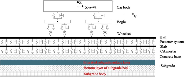
The CRTS-Ⅱ slab ballastless track of the China railway track system is constructed using rails, rail pads, track slabs, CA mortar, concrete support and subgrade bearing layers as shown in Fig. 1. In this study, according to the wheel/rail system coupling dynamics theory [24], a vertical coupling vibration calculation model of the vehicle-slab track-subgrade system, which is shown in Fig. 2, is established. The train is modeled as an assembly of rigid bodies connected by springs and dampers forming a 10 DOF system [25]. The mass of the car, bogies and wheels as well as the longitudinal rotation inertia of car and bogies are included. The calculation of the contact force between the wheel and the rail is described by the nonlinear Hertz contact theory. A train is assumed to move at a constant speed in the positive direction. Assuming that on the rail surface there is a sinusoidal track irregularity, the contact force between the wheel and rail may be expressed as:
where Fc denotes the Hertzian contact force; and Kh the Hertz spring constant; wr, uz and ww denote, respectively, the displacement of the rail at a contact point, rail surface irregularity and wheel displacement in contact with the rail; A and λt denote the amplitude and wavelength of the rail irregularity, respectively.
The rail and slab layer are modeled as Euler-Bernoulli beam elements, and the concrete base layer is described as elastic medium. The rail pads and CA mortar are assumed to act as linear springs and dashpots. The subgrade bearing layers consist of surface and bottom layers of the subgrade bed and subgrade body. As a matter of fact, in addition to the case that the surface layer of the subgrade bed is frequently under the saturated condition relatively, the bottom layer of the subgrade bed and subgrade body are rarely saturated due to the drainage system [26]. Hence, the wet surface layer of the subgrade bed is modeled as water-saturated porous media, the bottom layer of the subgrade bed and subgrade body are considered as a dry and elastic layer where there are no water.
Fig. 2Vehicle-slab track-subgrade vertical coupling vibration plane model
2.1. Moving finite element of Euler-Bernoulli beam
The rail and concrete slab are modeled as Euler-Bernoulli beams resting on the concrete base layer in the positive x direction. The origin of the fixed x axis is arbitrarily located along the beam. However, for convenience, its origin is taken such that the center of train is at x=0 when t=0. The governing equation for the rail beam is given by:
+kt(ws-vb)-kr(wr-ws)=0,
where wr, ws and vb are deflection magnitudes of the rail, concrete slab and concrete base, respectively. ErIr and EtIt represent flexural stiffnesses of the rail and concrete slab, respectively. mr and mt are masses of the rail, concrete slab per unit length of the track, respectively. kr, cr are stiffness and damping coefficients of the fastening systems per unit length, respectively. kt and ct are stiffness and damping coefficients per unit length of the track, respectively, resulting from the CA mortar. F(t) is the wheel-rail contact force, V is the train moving velocity and δ is the Dirac delta function.
The moving element method (MEM) employs a moving spatial coordinate system where the origin is attached to the center of train. Fig. 2 shows the moving X axis, whose origin is fixed at the same position of x axis and is thus traveling at the same velocity as the train speed. Hence, the X axis shown in Fig. 2 is stationary in the moving train’s frame of reference. The relation between the two coordinates is given by:
In view of Eq. (5), the governing equation in Eqs. (3-4) may be rewritten as:
+kr(wr-ws)=-F(t)δ(X),
-cr(∂wr∂t-V∂wr∂X-∂ws∂t+V∂ws∂X)+kt(ws-vb)-kr(wr-ws)=0.
Using the Galerkin’s method in the governing equation Eq. (6), taking δwr as the admissible virtual variation of the rail displacement wr and then integrated over the element length, leading to the weak form as follows:
+cr(∂wr∂t-V∂wr∂X-∂ws∂t+V∂ws∂X)+kr(wr-ws)+F(t)δ(X)}dX=0.
Applying the Green-Gauss theorem:
+mrV2(δwr∙∂wr∂X)l0-mrV2l∫0∂δwr∂X∙∂wr∂XdX-2mrVl∫0δwr∂2wr∂X∂tdX
+krl∫0δwr(wr-ws)dX+crl∫0δwr(∂wr∂t-V∂wr∂X-∂ws∂t+V∂ws∂X)dX.
The mass, damping and stiffness matrices of the moving element for rail beam can be obtained as given below:
+crV∫l0NTrNt,XdX+kr∫l0NTrNrdX-kr∫l0NTrNtdX,
where (),X denotes the partial derivative with respect to X and (),XX denotes the second partial derivative with respect to X. In addition, Nr and Nt refer to the vector of shape functions for the displacement of the rail and concrete slab, respectively.
Meanwhile, in a similar way, the mass, damping and stiffness matrices of the moving element for the concrete slab can also be derived:
-2mtV∫l0NTtNt,XdX,
+ctV∫l0NTtNbdX+crV∫l0NTtNr,XdX-crV∫l0NTtNt,XdX+kt∫l0NTtNtdX
-kt∫l0NTtNbdX-kr∫l0NTtNrdX+kr∫l0NTtNtdX,
where Nt and Nb refer to the vector of shape functions for the displacement of the concrete slab and concrete base, respectively.
2.2. Moving finite element of saturated soil
In this study, the dynamic Biot’s equation known as u-p formulation proposed by Zienkiewicz et al. [27] is used to govern the dynamic response of the poroelastic medium under dynamic loading. The u-p formulation describes the saturated porous media in terms of two variables, the displacement of the solid phase, u, and pore water pressure, p, and it is derived from two coupled equations, the equation of motion for the mixture neglecting the acceleration of pore water:
where i, j= 1, 2, corresponding to x, Z directions (in the rectangular coordinate system), respectively; σ'ij(i,j=x,Z) denotes the stress tensor of the solid phase; ui is the displacement vectors of the solid phase; p is the pore water pressure; ρ=ρfϕ+ρs(1-ϕ) is the mixture mass density, ρf is the fluid density, ρs is the solid density, ϕ is the porosity; δij denotes the Kronecker delta, εii is the dilatation of the solid matrix, εij is the strain component of the solid matrix; k represents the permeability; γw is the unit of pore water and Kf is the pore fluid bulk modulus; α is the Biot’s coefficient; λ, G are lame constants of the solid phase.
In view of Eq. (5), the governing equation in Eqs. (16-17) may be rewritten as:
Using the Galerkin’s method in the Eq. (16) and Eq. (17), taking δui as the admissible virtual variation of the solid phase displacement vector, ui and δp as the admissible virtual variation of the fluid phase pressure field, p, one founds the weak form as:
=∫Ωδ(ρ¨ui-2Vρ˙ui+V2ρui,XX)δuidΩ,
+∫Ωδp(ϕ/Kf)(˙p-Vp,X)dΩ-∫Γδp(k/γw)p,inidΓ=0,
where Ω and Γ denote the poroelastic domain and its boundary, respectively. The vector ni is the unitary normal.
Via the Galerkin technique using the approximations ui=Nu¯u and p=Np¯p, where Nu and Np are arrays of interpolation functions for displacement and pressure, respectively, and ¯uand ¯p are vectors of nodal displacements and pore pressures, the matrixes of the moving element for saturated soil can be obtained as given below:
where:
K=∫ΩBTDBdΩ+ρV2∫ΩNTuNu,XXdΩ,Q=α∫Ω(∇∙Nu)TNpdΩ,
S=(ϕ/Kf)∫ΩNTpNpdΩ,Kp=-αV∫Ω(∇∙Nu,X)TNpdΩ,
H=(k/γw)∫Ω∇NTpNpdΩ-V(ϕ/Kf)∫ΩNTpNp,XdΩ,
fu=∫ΓNTutdΩ,fp=∫ΓNTpqdΩ,
where B is the strain-displacement matrix, D is the stress-strain matrix, t is a boundary traction for the solid phase, q is a boundary flux for the fluid phase.
2.3. Moving finite element of elastic medium
The saturated medium can be degraded into the case of corresponding elastic medium when in absence of the pore pressure. Its governing equations can be written by the Navier equation. Similarly, we can derive the finite element equations for elastic medium as:
where:
Ke=∫ΩBTeDeBedΩ+ρeV2∫ΩNTeuNeu,XXdΩ,feu=∫ΓNTeutedΩ,
where Me, Ce and Ke are the mass, damping and stiffness matrices, respectively, Neu is the displacement shape function of the elastic medium,ˉue is vector of nodal displacement of the elastic medium,Be is the strain-displacement matrix, and De is the stress-strain matrix for elastic medium, te is a boundary traction.
2.4. Coupling boundary conditions of subgrade surface layer
In the subgrade module, unlike other vehicle–slab track–subgrade coupling model studies that solve the responses of subgrade and track as a whole system, the present subgrade model as shown in Fig. 2, includes an internal boundary condition to ensure the normal gradient of pore water pressure equal to zero at the impermeable surface of the surface layer of the saturated subgrade bed. In addition, no relative displacement and the total normal stress equilibrium are imposed at the subgrade surface layer internal boundaries. Hence, the continuities of the displacement, total normal stress and no fluid flow at the interfaces for the subgrade surface layer are given by:
here, ue and σe represent the displacement and total stress for the elastic medium, respectively. u and σ' are displacement and effective stress, respectively, and p is the pore water pressure for the subgrade surface layer. n is the outward normal unit vector.
The total stiffness matrix, total mass matrix and total damping matrix for the coupling system can be formulated by the conventional assembling technique in the FEM. These motion equations can be solved by using the Newmark integral algorithm, which is widely used in the analysis of engineering problems. Based on the moving finite element model described in the above, a computer simulation program with Matlab, was developed to analyze the dynamic hydro-mechanical response of the saturated subgrade surface layer in the coupled vehicle-slab track- subgrade system.
3. Moving element method validation
As there are no results available in the literature on the dynamic response of the water saturated subgrade surface layer under high speed train, in order to examine the accuracy of the proposed computational scheme in conjunction with the MEM, a comparison is made against available analytical dynamic response for the case of a saturated poroelastic medium under a moving load obtained by Theodorakopoulos [8]. The poroelastic parameters are the same as those used in Theodorakopoulos [8]. Fig. 3(a) shows the vertical displacements distributed along the vertical direction for the moving load velocity V=20 m/s. It can be seen that the comparison results are in good consistency. Fig. 3(b) presents comparisons of the pore water pressure between numerical results and the data of Theodorakopoulos [8] for the moving load velocity V=20 m/s and 100 m/s. It can be seen that a good correspondence is observed.
Another comparison is made to validate the above new approach for the dynamic response of the vehicle and slab track coupling system. It should be noted that the dynamic behavior of the vehicle and slab track coupling system was conducted by Lei [23], based on the moving element method. Hence, the same vehicle, and slab track parameters as those in Lei [23] were used as input. In addition, the rail was considered as smooth, and the time step was chosen to be 0.0001 s in the computation. In Fig. 4, the wheel-rail contact fore and rail displacement at the contact point for the vehicle at 50 m/s obtained by present work were compared. It can be seen that the curves are in good agreement with each other.
Fig. 3Comparison between present work and Theodorakopoulos’s [8] work
![Comparison between present work and Theodorakopoulos’s [8] work](https://static-01.extrica.com/articles/18187/18187-img4.jpg)
a) Vertical displacement
![Comparison between present work and Theodorakopoulos’s [8] work](https://static-01.extrica.com/articles/18187/18187-img5.jpg)
b) Pore water pressure
Fig. 4Comparison between present work and Lei et al. [23] work
![Comparison between present work and Lei et al. [23] work](https://static-01.extrica.com/articles/18187/18187-img6.jpg)
a) Wheel-rail contact force
![Comparison between present work and Lei et al. [23] work](https://static-01.extrica.com/articles/18187/18187-img7.jpg)
b) Rail displacement
4. Numerical results and discussion
In this model, The Chinese high-speed train CRH3 is used as a passenger train. The parameters for the Chinese high-speed train CRH3 are listed in Table 1 and correspond to those used in Lei et al. [23]. The parameters of the slab track, and subgrade are listed in Table 2 and are selected based on a reference to Lei et al. [23] and Han et al. [28]. The parameters are selected according to Tables 1 and 2 unless otherwise denoted in the figures. The main physical quantities of interest in this investigation are the dynamic responses of the saturated subgrade surface layer with high-speed train loading. The variations of these quantities with respect to the parameters of train velocity, the subgrade surface layer permeability, drainage boundary, elastic modulus and rail irregularity are studied.
Table 1High-speed train CRH3 parameters
Parameters | Value |
Car body mass, Mc(kg) | 40,000 |
Bogie mass, Mt(kg) | 3200 |
Axle mass, Ma(kg) | 2400 |
Secondary suspension stiffness,Ks(MN/m) | 0.8 |
Secondary suspension damping, Cs(kN∙s/m) | 120 |
Primary suspension stiffness, Kp(MN/m) | 2.08 |
Primary suspension damping, Cp(kN∙s/m) | 100 |
Wheel base 2l1(m) | 2.5 |
Distance between bogie centers 2l2(m) | 17.375 |
Stiffness of wheel–rail contact Kh (MN/m) | 1.325×10³ |
Axle load, P (kN) | 140 |
Table 2Slab track parameters
Parameters | Value |
Mass of rail beam mr(kg/m) | 60 |
Bending stiffness of rail beam ErIr (kN∙m2) | 6756 |
Mass of concrete slab mt(kg/m) | 1275 |
Bending stiffness of slab EtIt(kN∙m2) | 3315 |
Rail pad stiffness kr(MN∙s/m2) | 60 |
Rail pad damping cr(kN/m2) | 47.7 |
CA mortar stiffness kt(MN/m2) | 900 |
CA mortar damping ct(kN∙s/m2) | 83 |
Elastic modulus of Concrete base Eb(MPa) | 34000 |
Density of concrete base ρb(kg/m3) | 2500 |
Poisson’s ratio of concrete base | 0.2 |
Thickness of concrete base (m) | 0.3 |
Table 3Subgrade soil parameters
Layers | Surface layer | Bottom layer | Subgrade body |
Thickness (m) | 0.4 | 2.3 | 1.2 |
Elastic modulus E (MPa) | 200 | 150 | 100 |
Poisson’s ratio ν | 0.25 | 0.3 | 0.35 |
Solid density ρs(kg/m3) | 2300 | – | – |
Water density ρf(kg/m3) | 1000 | – | – |
Soil density ρ(kg/m3) | 2040 | 1950 | 1900 |
Porosity ϕ | 0.2 | – | – |
Compressibility parameter α | 0.95 | – | – |
Fluid viscosity η(Pa∙s) | 0.001 | – | – |
Permeability k (m/s) | 1×10⁻⁴ | – | – |
4.1. Comparison between saturated and elastic subgrade surface layer
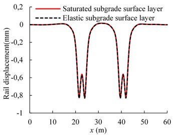
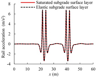
Figs. 5-6 show the comparison of the dynamic responses for the cases of saturated and elastic subgrade surface layer for the train running at the speed of 70 m/s. As shown in the Fig. 5, the variation trends for the rail displacements and accelerations in different cases are similar. This is likely because, when the train moves along the track, the stress waves propagate first through the subgrade surface layer and then arrive at the subgrade other parts. Then, the differences of rail dynamic responses become less noticeable with a thinner subgrade surface layer. Meanwhile, it can be observed in Fig. 6 that the great differences of the vertical displacement and the vertical total stress are available in the depth direction along the subgrade between saturated and elastic subgrade surface layer. As the whole, the vertical displacement and total stress under the condition of saturated subgrade surface layer are larger than that of the elastic case. The reason is that the pore water has a much higher modulus than the soil skeleton in the subgrade surface layer, which results in higher subgrade surface layer stiffness. In this case, the larger dynamic stress at the subgrade top is generated by the moving train. In addition, the pore water in the saturated subgrade surface layer could help to reduce the effective stress and decrease the vertical amplitude. Hence, the differences are formed by the competition of the opposite factors.
Fig. 5Comparison of rail dynamic responses
a) Rail displacement
b) Pore water pressure
Fig. 6Comparison of subgrade dynamic responses
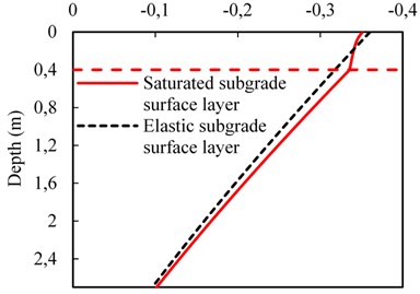
a) Vertical displacement
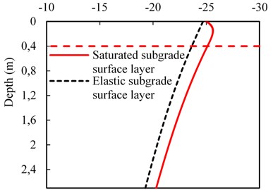
b) Vertical total stress
4.2. Train velocity influence
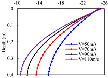
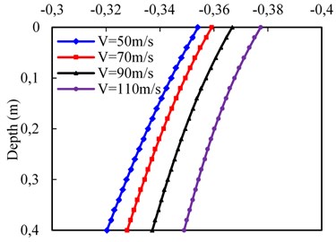
Fig. 7 presents the effect of the train velocity on the dynamic responses at the subgrade surface layer. Here, four different velocities are considered, i.e., 50, 70, 90, and 110 m/s. the top and bottom of the subgrade surface layer are assigned to the drained and undrained condition, respectively, and other parameters were listed in Tables 2 and 3. As shown in Fig. 7(a), the pore water pressure gradually increases in the depth direction along the subgrade surface layer and the distribution trends along depth are almost similar at different train velocities for the permeability k=10-4 m/s. Meanwhile, the dynamic influence on pore water pressure becomes deeper with the increasing train velocity. The maximum pore water pressure grows up with the increasing train velocity, while the maximum pore water pressure growth rate decreases. For instance, when the train velocity between 50 m/s and 110 m/s in increments of 20 m/s, the maximum pore water pressure increases by 31.3, 18.9 and 12.9 %, respectively. In addition, the variation of vertical effective stress against depth can be observed in Fig. 7(b). As expected, the vertical effective stress gradually decreases in the depth direction and the higher pore water pressure will lead to the lower vertical effective stress.
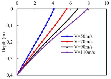
According to Fig. 7(c), the vertical displacement with depth decreases gradually at different train velocities due to the loading wave propagation. In addition, a higher train velocity will lead to a higher maximum vertical displacement, and the maximum vertical displacement growth rate increases. For example, when the train velocity is between 50 m/s and 110 m/s in increments of 20 m/s, the maximum vertical displacement increases by 14.1, 22.3 and 27.2 %. It should be noted that the chosen train velocity is less than the shear velocity of the subgrade body, which is the smallest in subgrade components. As it can be seen from Fig. 7(d), the vertical velocity of pore water also decays with the depth due to the pore water can flow freely through the top surface. The vertical velocity of pore water included by higher train velocity is larger than that of a lower velocity and the maximum vertical velocity of pore water growth rate increases with the increasing train velocity.
Fig. 7Effect of train velocity on dynamic responses of subgrade surface layer
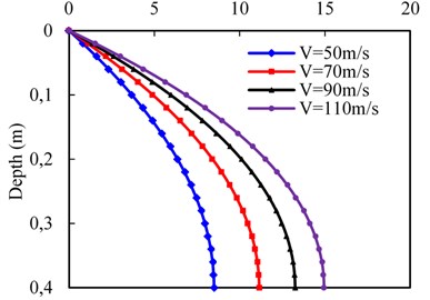
a) Pore water pressure
b) Vertical effective stress
c) Vertical displacement
d) Vertical velocity of pore water
4.3. Permeability effect
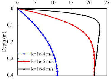
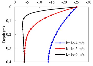
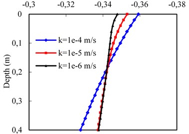
The permeability effect on the dynamic responses at the subgrade surface layer is studied, using different values of subgrade surface layer permeability, namely 1×10⁻⁴, 1×10⁻⁵, and 1×10⁻⁶ m/s, as shown in Fig. 8. The train velocity is 70 m/s and other parameters were same as above mentioned. The pore water pressure response against the depth is investigated in Fig. 8(a). It can be observed that the maximum pore water pressure increases as the permeability decreases, and reaches the maximum value shifting towards the region near the surface of subgrade correspondingly. In other words, for the coarse material, the variation of pore water pressure against depth is gradual after its maximum value being reached, but for the fine material, the pore water pressure grows up rapidly to reach its maximum value in the region near the surface and then relatively decreases gradually. However, the vertical effective stress against depth increases with the increase of permeability, as shown in Fig. 8(b). This is due to the face that the increase of pore water pressure will lead to a smaller vertical effective stress based on the principle of effective stress [28].
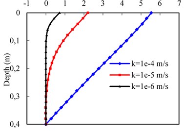
According to Fig. 8(c), it can be seen that the vertical displacement increases with depth as the permeability increases according to the variation of vertical effective stress in the upper region. However, the vertical displacement in the bottom region decreases as the permeability increases, because of the total stress at the interface between surface layer and bottom layer of the subgrade bed increases for a small permeability value, and the bottom layer of the subgrade bed undertakes more load. Thus, the vertical displacement of the surface layer increases due to the deformation of the bottom layer of the subgrade bed. It indicates at that the variation of the subgrade surface layer permeability has an influence on the deformation of the bottom layer of the subgrade bed.
Fig. 8(d) shows the distributions of vertical velocity of pore water with different subgrade surface layer permeability. The vertical velocity of pore water increases as the permeability increases, and the pore water just flows at the region near the surface for the lower permeability (k=10-6 m/s). In addition, for larger permeability (k=10-4 m/s), the value of the vertical velocity against depth changes from positive to zero, whereas, for the permeability k= 10-5 m/s, and 10-6 m/s, it changes from positive to negative and then falls down to zero. It can be seen that the interface location is where the maximum pore water pressure occurs. That is, the pore water flows towards the upper boundary above the interface, while the pore-water flows down to the bottom of subgrade surface layer beneath the interface. Similar observations were reported by Theodorakopoulos [8].
Fig. 8Permeability effect on dynamic responses of subgrade surface layer
a) Pore water pressure
b) Vertical effective stress
c) Vertical displacement
d) Vertical velocity of pore water
4.4. Influence of drainage boundary
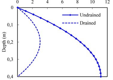
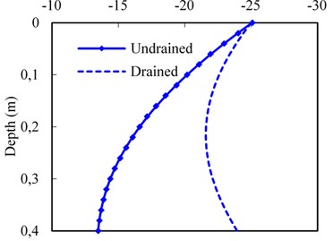
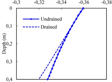
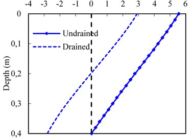
In order to study the effects of the drainage boundary conditions on the dynamic responses at the subgrade surface layer. Fig. 9 displays the pore water pressure, vertical effective stress, vertical displacement, and vertical velocity of pore water with depth in terms of drained and undrained boundary assigned to the bottom of the subgrade surface layer. The pore water pressure on the drained boundary condition is significantly smaller than that of one on undrained boundary condition as shown in Fig. 9(a). For drained condition, the pore water pressure decreases to zero gradually after reaching the maximum value. In other words, the vertical effective stress in the subgrade surface layer is significantly higher on the drained boundary condition (Fig. 9(b)), indicating at the reduction in mud pumping potential. Additionally, for different drainage boundaries, there is a small difference of the vertical displacement in the upper region of the subgrade surface layer, but the result has a large difference in the bottom region as shown in Fig. 9(c). It’s due to the fact that the distribution of the vertical effective stress with depth and total stress acting on the bottom layer of the subgrade bed, the gap of the vertical displacement becomes broader for the drained/ undrained condition.
Fig. 9Effect of drainage boundary on dynamic responses of subgrade surface layer
a) Pore water pressure
b) Vertical effective stress
c) Vertical displacement
d) Vertical velocity of pore water
Fig. 9(d) presents the drained boundary affects the velocity of pore water evidently compared with the undrained boundary condition. For the drained condition, the value of the vertical velocity against depth changes from positive to negative, due to the fact that the pore water can flow through the boundary freely at the bottom of subgrade surface layer, which facilitates to dissipate the pore water pressure. But for the undrained condition, vertical velocity against depth changes from positive to zero, indicating at that the pore water is confined to flow towards the upper surface. Thus, the velocity of pore water for the drained condition is higher than that under the condition of undrained boundary nearby the bottom of the subgrade surface layer. Furthermore, the pore water pressure is lower, and the vertical effective stress is higher relatively for the drained condition (Fig. 9(a-b)). From a practical point of view, a good drainage system should be set up to provide the improved performance in terms of reduction in mud pumping problems on the subgrade surface layer.
4.5. Effect of subgrade surface layer modulus
The maximum pore water pressure (pwp) and vertical velocity of pore water (vpwp) changing with subgrade surface layer modulus are shown in Fig. 10. In Fig. 10(a), the maximum pore water pressure decreases with the increases in subgrade surface layer modulus. For example, the maximum value of the pore water pressure can decrease by 36.6 % as surface layer modulus increases from 160 to 360 MPa for undrained condition. It is observed that the maximum pore water pressure decreases nonlinearly with the increasing subgrade surface layer modulus. That is, the bigger modulus produces smaller pore water pressure. This phenomenon can be explained as follows: the compressive strength is higher, and the deformation of soil skeleton is smaller when the modulus of the subgrade surface layer is larger. A similar law with variation of subgrade surface layer modulus can be observed in Fig. 10(b). For instance, the maximum vertical velocity of pore water pressure can decrease by 40.7 % as subgrade surface layer modulus increases from 160 to 360 MPa for undrained condition. From the figures, the subgrade surface layer modulus exerts significant influence on hydro- dynamic response in the subgrade surface layer. Therefore, reasonable subgrade surface layer modulus should be controlled to alleviate potential mud-pumping problems.
Fig. 10Effect of modulus on dynamic responses of subgrade surface layer
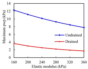
a) Maximum pore water pressure
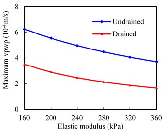
b) Maximum vertical velocity of pore water
4.6. Effect of rail irregularity
The rail irregularity is an important factor that can influence the magnitude of wheel-rail force, and the dynamic responses in the subgrade surface layer are generated mainly by the wheel-rail force. Fig. 11 shows the pore water pressure of the bottom of the subgrade surface layer plotted against the amplitude A for two irregularity wavelengths, λt=1 m and λt= 5 m, at vehicle speed V= 50 m/s. The irregularity period is thus 0.02 s and 0.1 s, respectively. As the track irregularity is a sinusoidal function, the dynamic responses of the pore water pressure exhibit the sinusoidal form.
Fig. 11Effect of rail irregularity on pore water pressure of bottom of subgrade surface layer
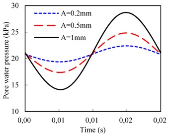
a) Wavelength, λt=1 m
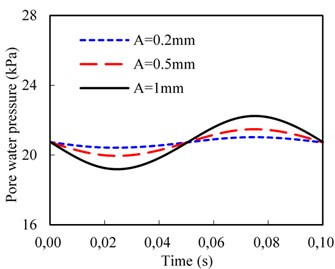
b) Wavelength, λt=5 m
It can be seen from Fig. 11(a) that the maximum amplitude of the pore water pressure increases significantly with the increasing amplitude of the rail irregularity. For example, the maximum value of the pore water pressure can increase by 25.9 % as the irregularity amplitude increases from 0.2 to 1 mm for wavelength λt= 1 m. However, when the track irregularity wavelength increases to 5 m, as shown in Fig. 11(b), the maximum amplitude of the pore water pressure is smaller than that of the wavelength λt= 1 m. For instance, the maximum value of the pore water pressure increases by 5.8 % as the irregularity amplitude increases from 0.2 to 1 mm for wavelength λt= 5 m.
5. Conclusions
In this work, based on moving element method, a vehicle-slab track-subgrade model for the prediction of the hydro-mechanical response in subgrade surface layer is developed. The train is considered as a rolling stock unit with a primary and secondary suspension system. The rail and the concrete slab are modeled as Euler–Bernoulli beams. The u-p formulation is used to consider the interaction of the pore water and soil skeleton in the subgrade surface layer. The concrete base layer and other subgrade components are regarded as elastic medium. By using the coupling model, the effects of train velocity, subgrade surface layer permeability, drainage boundary, elastic modulus and rail irregularity on dynamic responses of the saturated subgrade surface layer are investigated. The main conclusions of this study can be summarized as follows:
1) The results obtained using the MEM with the proposed computational procedure to account for the dynamic responses of the saturated poroelastic medium under the moving load and the vehicle-slab track-subgrade systems are found to agree well with results obtained by other researchers, which at least suggest that the matrices of the moving element and corresponding computations are correct and reasonable. Because of eliminating the need for keeping track of the contact point with respect to individual elements, the proposed computational procedure in conjunction with the MEM is computationally more efficient.
2) The difference of the rail dynamic response for the case of saturated and elastic subgrade surface layer is less noticeable, when the train velocity is lower. However, the difference of the subgrade dynamic response is large. It is due to the variation of the stiffness and the effective stress in the subgrade surface layer which caused by the pore water.
3) The train velocity significantly affects the development of the hydro-mechanical response in the saturated subgrade surface layer. Generally speaking, the higher velocity can lead to higher pore water pressure, higher pore water velocity and higher vertical displacement. In addition, the subgrade surface layer permeability, drainage boundary and train velocity as well as the rail irregularity have significant influence on the hydro-mechanical response.
4) The pore water pressure increases as the permeability decreases, indicating at potential mud pumping problems on such a subgrade surface layer for fine materials. In terms of reduction in mud pumping problems, a good drainage system should be set up to facilitate rapid drainage and pore water pressure dissipation. In addition, the increase of the subgrade surface layer modulus can also reduce the pore water pressure and vertical velocity of pore water. Therefore, the reasonable subgrade surface layer modulus should be controlled to alleviate potential mud pumping problems.
References
-
Jiang H., Bian X. C., Jiang J. Q., Chen Y. M. Dynamic performance of high-speed railway formation with the rise of water table. Engineering Geology, Vol. 206, 2016, p. 18-32.
-
Kettil P., Lenhof B., Runesson K., Wiberg N. E. Coupled simulation of wave propagation and water flow in soil induced by high-speed trains. International Journal for Numerical and Analytical Methods in Geomechanics, Vol. 32, Issue 11, 2008, p. 1311-1319.
-
Zhai W., Song E. Three dimensional FEM of moving coordinates for the analysis of transient vibrations due to moving loads. Computers and Geotechnics, Vol. 37, Issue 1, 2010, p. 164-174.
-
Sheng X., Jones C. J. C., Thompson D. J. A theoretical study on the influence of the track on train-induced ground vibration. Journal of Sound and Vibration, Vol. 272, Issue 3, 2004, p. 909-936.
-
EI Kacimi A., Woodward P. K., Laghrouche O., Medero G. Time domain 3D finite element modelling of train-induced vibration at high speed. Computers and Structures, Vol. 118, Issue 8, 2013, p. 66-73.
-
Correia A. G., Cunha J. Analysis of nonlinear soil modelling in the subgrade and rail track responses under HST. Transportation Geotechnics, Vol. 1, Issue 4, 2014, p. 147-156.
-
Biot M. A. Theory of propagation of elastic waves in a fluid‐saturated porous solid. Part I: Low-frequency range. Part II: High-frequency range. Journal of the Acoustical Society of America, Vol. 28, Issue 2, 1956, p. 168-191.
-
Theodorakopoulos D. D. Dynamic analysis of a poroelastic half-plane soil medium under moving loads. Soil Dynamics and Earthquake Engineering, Vol. 23, Issue 7, 2003, p. 521-533.
-
Cai Y. Q., Sun H. L., Xu C. J. Steady state responses of poroelastic half-space soil medium to a moving rectangular load. International Journal of Solids and Structures, Vol. 44, Issue 22, 2007, p. 7183-7196.
-
Sun L., Gu W., Luo F. Steady-state wave propagation in multilayered viscoelastic media excited by a moving dynamic distributed load. Journal of Applied Mechanics, Vol. 76, Issue 4, 2009, p. 15.
-
Lu Z., Yao H., Zhan Y., Hu Z. Vibrations of a plate on a two-parameter foundation subjected to moving rectangular loads of varying velocities. Journal of Vibroengineering, Vol. 16, Issue 3, 2014, p. 1543-1554.
-
Lu Z., Hu Z., Yao H. L. An analytical method for evaluating highway embankment responses with consideration of dynamic wheel-pavement interactions. Soil Dynamics and Earthquake Engineering, Vol. 83, 2016, p. 135-147.
-
Lenhof B., Kettil P., Runesson K., Wiberg N. E. Assessment of acceleration modelling for fluid-filled porous media subjected to dynamic loading. International Journal for Numerical and Analytical Methods in Geomechanics, Vol. 32, Issue 2, 2008, p. 109-119.
-
Gao G. Y., Chen Q. S., He J. F., Liu F. Investigation of ground vibration due to trains moving on saturated multi-layered ground by 2.5 D finite element method. Soil Dynamics and Earthquake Engineering, Vol. 40, 2012, p. 87-98.
-
Saad B. Analysis of excess water impact on the structural performance of flexible pavements. International Journal of Pavement Engineering, Vol. 15, Issue 5, 2014, p. 409-426.
-
Lu J. F., Jeng D. S., Williams S. A 2.5-D dynamic model for a saturated porous medium. Part II: Boundary element method. International Journal of Solids and Structures, Vol. 45, Issue 2, 2008, p. 359-377.
-
Ang K. K., Dai J. Response analysis of high-speed rail system accounting for abrupt change of foundation stiffness. Journal of Sound and Vibration, Vol. 332, Issue 12, 2013, p. 2954-2970.
-
Koh C. G., Ong J. S. Y., Chua D. K. H., Feng J. Moving element method for train-track dynamics. International Journal for Numerical Methods in Engineering, Vol. 56, Issue 11, 2003, p. 1549-1567.
-
Krenk S., Kellezi L., Nielsen S. R., Kirkegaard P. H. Finite elements and transmitting boundary conditions for moving loads. 4th European Conference on Structural Dynamics, 1999. p. 447-452.
-
Kok A. W. Finite element models for the steady state analysis of moving loads. Heron, Vol. 45, 2001, p. 53-61.
-
Koh C. G., Sze P. P., Deng T. T. Numerical and analytical methods for in-plane dynamic response of annular disk. International Journal of Solids and Structures, Vol. 43, Issue 1, 2006, p. 112-131.
-
Koh C. G., Chiew G. H., Lim C. C. A numerical method for moving load on continuum. Journal of Sound and Vibration, Vol. 300, Issue 1, 2007, p. 126-138.
-
Lei X. Y., Wang J. Dynamic analysis of the train and slab track coupling system with finite elements in a moving frame of reference. Journal of Vibration and Control, Vol. 20, Issue 9, 2014, p. 1301-1307.
-
Zhai W. M., Wang K. Y., Cai C. B. Fundamentals of vehicle-track coupled dynamics. Vehicle System Dynamics, Vol. 47, Issue 11, 2009, p. 1349-1376.
-
Sadeghi J., Fesharaki M. Importance of nonlinearity of track support system in modeling of railway track dynamics. International Journal of Structural Stability and Dynamics, Vol. 13, Issue 1, 2013, p. 1-16.
-
Liu B., Pham D. P., Su Q., Gui B. Deformation characteristics of subgrade graded gravel with different water contents. Rock and Soil Mechanics, Vol. 37, Issue 5, 2014, 1365-1372.
-
Zienkiewicz O. C., Shiomi T. Dynamic behaviour of saturated porous media; the generalized Biot formulation and its numerical solution. International Journal for Numerical and Analytical Methods in Geomechanics, Vol. 8, Issue 1, 1984, p. 71-96.
-
Han J., Zhao G. T., Sheng X. Z., Jin X. S. Study on the subgrade deformation under high-speed train loading and water-soil interaction. Acta Mechanica Sinica, Vol. 32, Issue 2, 2016, p. 233-243.
Cited by
About this article
The authors acknowledge the National Natural Science Foundation of China (No. 51378441, and 51578467) and Development Plan of the Chinese Railway Corporation (No. 2016G002-E).

