Abstract
Airtight blast door, as one of the key components of a rescue device or a ventilating device in underground coal mine, which can not only guarantee the normal operation ventilation system, but also can prevent the propagation of shock wave and invasion of toxic gases. Therefore, high structural stability and safety is fundamental when designing a door. An airtight blast door was developed and optimized based on static analysis and topological optimization, and dynamic response analysis of the optimized airtight blast door subjected to gas explosion load was conducted using a novel approach proposed in this paper-the FEM-SPH contact algorithm. Results showed that the main component weight of this kind of door is 27.4 % smaller than the original one without reducing the blast and impact behavior, the maximum displacement and stress of the optimization door obtained by FEM-SPH contact algorithm (dynamic response) are much larger than those using static mechanical analysis. The FEM-SPH contact algorithm and typical optimization method as well as the example presented in this paper are helpful for the original design and optimization of other products. Some conducive suggestions were recommended based on the simulation results.
1. Introduction
Coal mine gas explosion, without any doubt, has become one of the most serious disaster in coal mining process. The high temperature, high pressure and toxic gases pose a huge threat to the underground personnel lives, equipment and economic development after gas explosion [1]. Worse still, according to an incomplete statistic, there were about 900 accidents of gas explosion that killed more than 3 people each time from the year 2001 to 2012 in China [2]. Nowadays, the number of the explosive disasters shows a downward trend. However, the death toll per accident remains a horrible number, illustrating that the gas explosion accident still has not been effectively prevented and controlled.
Rescue devices such as refuge chamber and rescue capsule are the two most common refuge shelters for underground coal mines, which can provide refuge shelters for those who trapped in explosion and fire accidents underground mine and could not be evacuated adequately and promptly [3], and they have become one of the “six systems” that provided for coal mine risk prevention and numerous coal miners have been saved successfully [4]. However, the structure of coal mine rescue devices should be equipped with excellent antiknock feature and sealing performance so as to ensure the rescue efficiency in gas explosion and other disasters. Foremost, airtight blast door is the first barrier for a refuge chamber and rescue capsule for which can bear a certain intensity of shock wave and prevent the invasion of poisonous gases, there is no doubt that its performance directly decides the reliability and stability of the capsules or chambers. Consequently, to develop an airtight blast door with excellent antiknock feature and stable sealing performance is of great necessity for rescue effectiveness.
Nowadays, the design and development for airtight blast door has not yet attracted enough attention as for coal mine refuge shelters. Currently, many large equipment manufacturing companies, such as Mine ARC Systems, Shairzal Safety Engineering, Jack Kennedy Metal Products, Modern Mine Safety, Supply LLC, have been committed to design and safety evaluation of such a device [5]. In China, the government has made some relevant standards which demanded that all coal mines must be equipped with rescue equipment [6]. An airtight blast door must be stable and flexible so as to resist shock wave caused by gas explosion. Distortions and plastic deformations are not allowed in critical components, such as the observation windows, stiffeners and ribs. Of course, numerous studies have been performed on antiknock performance of blast door, on purpose of revealing its deformation mechanism and structural safety subjected to an explosion blast load [7]. The two commonly used approaches to examine the antiknock performance of the device are to conduct blast tests and numerical analysis, respectively. Fan [8] and Guo [9] carried out an experiment in a full-scale tunnel to test the anti-shock performance of recue capsule in a 40 m and 100 m tunnel with the explosion load of 200 m3 of gas/air mixture, the pressure value at different positions in real tunnel and the limitation of gas overpressure on the surface of the blast door are obtained. Continuously, some similar experiments have been implemented on the antiknock performance under different types of explosive loads by few researchers [10-15]. However, on one hand, it is expensive and time consuming to perform a large number of physical experiments to make strength assessment of an airtight blast door under explosion load. Meanwhile, physical experiments are unavailable to reveal the damage failure mechanism and dynamic response of the structures. Numerical simulation provides a systematic approach for anti-performance analysis of airtight blast door, which is low-cost, secure and repeatable.
Numerous studies have been focused on the influence of explosive load modes, the structure and reinforcement ratio on the mechanical properties of blast door. In previous literatures, most researchers simplified the blast load as a triangle shockwave [16-22] and even TNT equivalent method [23-24], yet their calculation results had enlarged the deviation from the real value. In fact, in order to design a blast door which is structural safety and lower cost, on the one hand, it is very necessary to optimize the structure parameters of an airtight blast door. On the other hand, both the static and dynamic response of the blast door requires to be considered. Meanwhile, many researchers [25-27] have proved that Smooth Particle Hydrodynamics algorithm, a more accurate and higher calculating algorithm than Lagrange and ALE approaches.
In this paper, our purpose is to optimize the structure of an original airtight blast door for in the premise of state standards requirements and conduct response analysis of the airtight blast door. To achieve this aim, we carried out a static response analysis and topology optimization for the original model, and conducted dynamic response analysis for the optimization model subjected to gas explosion load using FEM-SPH contact algorithm, which will provide a design thinking for structure analysis and performance evaluation of antiknock structures.
2. Computational codes
2.1. Basic principle for SPH algorithm
SPH algorithm is proposed by Lucy and GINGOLD [28-29], mainly used for Astrophysics and Universe. Up till now, it has become one of the oldest meshfree particle methods and is applied to deal with the dynamic response of solid structure for the first time in the year 1991 [30]. Nowadays, great advantages have been made in dealing with large deformation problems prompted by a long period of theoretical improvement [31]. SPH is a Lagrangian meshless particle method that can overcome the defects based on grid method. The free surfaces can be traced naturally in the process of simulation by proper distribution of the particles, therefore, it is suitable to follow large surface deformation involving free surface and interfacial [32]. A part simulated with SPH particles and can be defined a contact with FEM mesh in a model is called FEM-SPH coupling algorithm [33]. Such an algorithm can deal with the destruction of the material and large deformation in simulation process effectively, and it has aroused great concern in the application of explosion and shock dynamics.
The basic idea of SPH algorithm is to describe a domain with a series of particles and approximate the field function with integral representation. Prominently, such a method can elucidate the field function and its derivative at each time step based on the current support domain distribution of particles, as well as applying the particle approximation method to the related items of all the field functions.
2.2. SPH algorithm
The core idea of SPH algorithm is to establish a kernel function for kernel estimation of discrete particles so as to calculate various kinetic parameters, transform the conservation equations into integral equations in differential forms, and compute the kernel estimation of all the variables at an arbitrary point. The kernel estimation for function at a certain point in the space can be obtained by integral in the domain of :
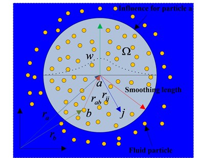
where, is spatial coordinate of the points to be estimated, is spatial point contributing to , is named as the kernel function or smooth function, is defined as a smoothing length of affected areas of smooth function , is integral or support domain. In SPH method, a smooth function satisfies the following conditions:
1) Positive and semi-definited, satisfies in the support domain.
2) Compactness, satisfies out of the support domain.
3) Normalization, .
4) decreases monotonously with the addition of , where .
5) If the scale of support domain approaches to zero, then the function converge towards .
6). The function is even and needs to be smoothed sufficiently.
The whole system of SPH method can be expressed by several finite particles with independent quality and independent space, the function of an arbitrary particle can be approximated by a smooth function of all the particles in a support domain that corresponding to the function value of a weighted average, as shown in Fig. 1.
Fig. 1Particle interactions in SPH within the influence domain governed by the kernel function
If the volume of a particle is applied to replace the infinite body element at the front integral of the particle , the mass of the particle can be stated as follows:
where, is density of particle , is numbers of particles in the support domain.
The continuous SPH integral of can be expressed in the following discrete form by particle approximations:
SPH method can be extended to the corresponding field of material under dynamic load. Given the elastic plastic effect of the material, differential statements of SPH in the whole stress-tensor space are deduced as below:
Mass conservation equation:
Momentum conservation equation:
Energy conservation equation:
Position equation of particle motion:
where, , , , , and are the density, mass, stress, velocity, internal energy and kernel function of a particle, respectively.
Smooth length is a crucial parameter in SPH method for which can affect the calculating efficiency and accuracy directly. If is too small in value, a lack of enough particles in the support domain will lead to a low accuracy. The calculating efficiency and accuracy will be affected greatly if is too large. Then, the changeable smooth length can be described as follows:
where, is velocity of a particle, is smoothing length vary with time in the support domain.
The smooth length will increase with the separation of particles in their expansion process, and will decrease with the vicinity of particles in their compression process. The number of particles in the support domain would be stable owing to a changeable smoothing length.
In this paper, we choose Gauss kernel function as the smooth function, which can be expressed as follows:
where, , and are the position vectors of the particles and , respectively.
2.3. FEM-SPH contact algorithm
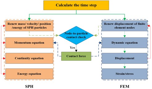
Fig. 2 shows the contact force added between SPH and finite elements, small solid circles represent the SPH particles, large dashed circle depicts the support domain of SPH particle , small dotted circles means background particles set on the finite element nodes. The background particles have their own SPH properties and can be passively searched by SPH particles. The mass, position, velocity and stress of a particle are updated according to the corresponding finite element nodes. Contact force generates as the distance between a finite element node and a SPH particle is two times of the smooth length. Calculation of the contact force refers to the contact idea of SPH algorithm, with regard to finite element nodes as particles, however, any SPH particle located at finite element node within the support domain will exert contact force on the nodes. Conversely, any finite element node in the support domain will impose contact force on a SPH particle. The calculation process is shown in Fig. 3.
Fig. 2Contact between SPH particles and finite elements
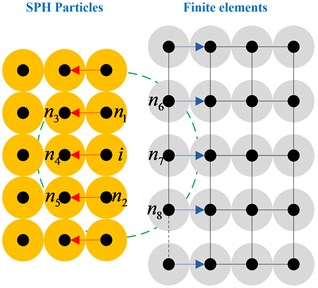
Fig. 3Solution procedure for SPH-FEM contact algorithm
A contact potential is defined in order to calculate the contact force:
where, is the numbers of particles that adjacent to particle in support domain but belongs to different bodies (finite element nodes for each particle), for particle (Fig. 1), , nodes , and will work on the particle . and are mass and density of particle , respectively. is the SPH smoothing kernel function, if both and belong to a same body, then . is the distance between two particles, is the average distance between different particles. and are user-defined parameters, and is similar to the contact stiffness in the finite element contact algorithm, affected by material properties and impact velocity.
The contact force between a SPH particle and a finite element node can be calculated as follows:
The direction of contact force is determined by the gradient of SPH smoothing kernel function, which can be considered as an external force of the SPH momentum equation and the finite element dynamic formulation, such a force can be calculated as follows:
where, is stress tensor of particle , is contact force exerted on particle . , , and are the displacement matrix, lumped mass matrix and stiffness matrix of FEM algorithm, respectively.
The integration of SPH and FEM is required to be synchronized in the Lagrange framework, and the data must be transmitted at the same time point. It is demanded that time step used in each step remains the same, therefore, selection for smaller time steps between the SPH and FEM is a good choice, that is:
where, and are time step of SPH and FEM algorithms, respectively. and are smooth length and the smallest unit size, respectively. is sound velocity of the material, and is scale coefficient of time step.
The FEM-SPH contact algorithm is consistent with the solution format of SPH. Accordingly, the contact force can be applied on the relevant particles (unnecessary to define) and nodes as long as the distance between the particle and the node is two times of smooth length. Different from the finite element contact algorithm, the SPH-FEM algorithm can be easily extended to 3D owing to the unnecessity of defining the contact interface and the normal direction at each time step.
2.4. Topology optimization algorithm
Topology optimization, a mathematical approach to optimize the material distribution in a certain region for the given load, constraint conditions and performance indexes and can be used for structure optimization, Structural optimization includes size optimization, shape optimization, topology optimization and topography optimization. The main research field of topology optimization consists of continuum topology optimization and discrete topology optimization. The continuum topology optimization method includes homogenization method, variable density method, evolutionary structure optimization (ESO) method and level set method. The basic idea of topology optimization is to find an optimal topology of the structure that can be transformed into a problem of finding the optimal material distribution in a certain designing area. Topology optimization design mainly includes three basic elements: design variables, constraint conditions and objective functions.
The mathematical model of optimal design can be expressed as follows:
Minimization:
Constraint conditions:
where, and are design variable and objective function, respectively. and are constraint conditions, superscripts and are upper limit and lower limit, respectively.
3. Numerical models and methods
3.1. Geometry and mesh
The structure of an airtight blast door must be strength enough so that can protect a structure against explosion shock wave and instantaneous high temperature once a gas explosion accident occurs. According to the design and development of an airtight blast door of a certain model, an airtight blast door was composed of 4 parts: explosion resistance structure, sealing structure, adiabatic structure and hand wheel. The original anti-knock structure of the original model is a rectangular knock back with a massive stiffened plate. Fig. 4(a) showed the shape and geometric model of the airtight blast door. Solid element is applied to express the entity structure and observation window. The observation window is welded on the top of the door. Table 1 lists the material type and thickness of each component on the structure.
Table 1Geometric parameters and materials of the airtight blast door
Component name | Material name | Thickness / mm |
stiffened plate | Q345B | 8 |
Door | Q345B | 15 |
Observation window | Hardened glass | 12 |
Taking the actual size of the model established above into account, the door hinge is described with rotatable elements mesh and the door shell is meshed with the mapping method and simulated using 163 element, each unit size was 0.01 m. Grid of the door is shown in Fig. 4(b).
Fig. 4Geometry and mesh of the original model
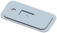
a) Geometry of the original model

b) Mesh of the original model
3.2. Material models and state equation
The process of impact and dynamic under gas explosion is a typical high-strain-rate phenomenon. The mechanical properties of steel and hardened glass will change noticeably when affected by the rate of explosive load. The yield strength of the material will increase substantially under high strain rate. In this paper, the nonlinear plastic material model PLASTIC-KINEMATIC proposed by Symonds and Cowper [34] is employed to simulate the strain rate effect of steel and hardened glass, constitutive curve of the model is described in Fig. 5.
where and are stress and strain of the material, respectively. and are Cowper-Symonds constants, the suggested values for steel are 40.4 and 5, respectively. is hardening parameter, which means that kinematic hardening if , but isotropic hardening if 1. is the initial yield stress, is the strain rate, is the effective plastic strain, is the yield strength, is the plastic hardening modulus and determined by the following calculation:
where, is the Yield hardening modulus, is the Elastic modulus. The nonlinear plastic material model PLASTIC-KINEMATIC is applicable for metal materials under blast loading. The calculated results are in consistent with the experimental data. The mechanical properties of material parameters are shown in Table 2.
Fig. 5Constitutive curve for steel and hardened glass. Where σ¯ and ε¯ are stress and strain, respectively
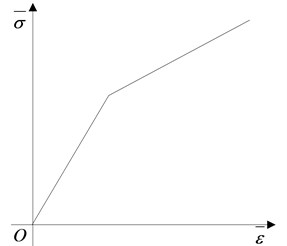
Table 2Parameters used in state equation of steel and hardened glass
Material name | Yield strength / MPa | Hardening modulus / MPa | Elastic modulus / GPa | Poisson ratio | Failure strain |
Steel / Q345B | 345 | 1180 | 201 | 0.3 | 0.35 |
Hardened glass | 70 | 73 | 0.35 | 0.32 |
3.3. Simulation assumptions
Some further hypotheses need to be made in order to eliminate the impact of various unfavorable factors:
a) Regardless of the changes of material properties and the influence of welding angle on the structure.
b) Material is homogeneous and isotropic.
c) Deformation caused by production and installation can be ignored, and relative movement between different components can be without consideration.
d) The bolt connection is reliable, and pre-stress has no effect on the whole structure.
3.4. Topology optimization and dynamic response for a structure under gas explosion load
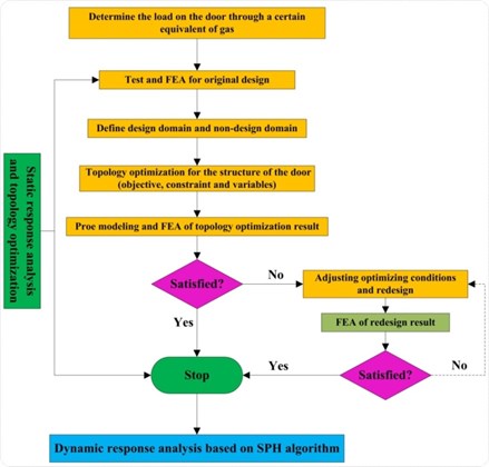
In this paper, ANSYS is applied to conduct shape and structure optimization of a structure. There is no doubt that the load (static load and dynamic load) on a structure should be determined firstly, and the next is to establish finite element model of the structure, exert loading, displacement constraints based on the boundary conditions, and define the optimization variables, objective function, constraint functions and optimal parameters and finally submit to the solution. The flow chart of topology optimization and mechanical response analysis for a structure is shown in Fig. 6.
Fig. 6Flow chart for topology optimization and mechanical response of a structure based on topology and FEM-SPH
4. Static response for the original model
4.1. Models and conditions
Fluid-solid coupling algorithm can be employed to simulate the explosion of the initial point, shock wave propagates and the interaction between shock wave and structures. However, it is inevitable to generate a large number of units and lead to variation for a long time using such an algorithm [3]. In this work, according to the requirements specification of numerical simulation, the gas explosion load can be simplified as the shock wave induced by a volume of 200 m3 that 100 m away from the structure in a tunnel.
Fig. 7Schematic diagram of impact load
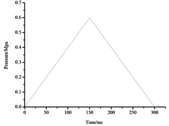
However, explosion shock wave interacts with the structure is a typical transient process, in accordance with equivalent momentum, blast shock wave can be transformed into a triangular shock wave which is evenly applied to the surface of airtight blast door [35]. Here, the triangular shock wave loading curve is determined by three parameters: the peak overpressure, time of pressure increasing and actuation duration of overpressure. The maximum pressure of the triangle shock wave is 0.6 MPa, and the pulse width is 300 ms. The impact load curve is shown in Fig. 7.
Airtight blast door is the main part of a coal mine rescue capsule or refuge chamber, therefore, the damage modes and criterion of airtight blast wall fit in well with that of the coal mine rescue devices, as given in Table 3 [36]. Based on the relative deformation of the main body structure, the damage modes and failure of the key components of the door can be evaluated according to the criteria of the numerical simulation.
Table 3Damage modes and criterion for the key components of airtight blast door.
Criterion | ||
Damage modes | Analysis project | Index |
Damage failure | Strength of key components | >Yield strength |
Sealing failure | Relative displacement of the connecting pieces | > 2 % or > 20 mm for shell |
> 1 % or > 10 mm for beam | ||
As it can be seen from Table 3, the deformation failure condition for the airtight blast door is that the maximum deflection of plate is no less than 2 % or the deformation is larger than 20 mm. Furthermore, the failure condition is that the maximum stress exceeds yield strength of the material, the failure condition for sealing is that the relative displacement of required connection requirements is larger than 1 mm or the deformation is larger than 10 mm.
4.2. Stress field
The stress contours of the door at different moments are shown in Fig. 8, which indicates that the pressure is gradually increased from blue to red.
As it can be seen from Fig. 8, higher stress appears at the door while lower stress on the stiffened plate. Influenced by the bolt connection and rigid connection, it is easy for the plate to generate stress concentration. Therefore, the overall strength of the door would be affected by the reinforcement method.
Fig. 8Stress contours for the original model
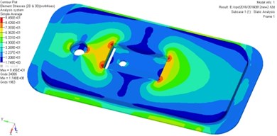
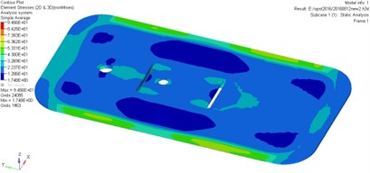
The bolt should be rigid enough so as to meet the antiknock performance under gas explosion load in actual working conditions. The safety factor of the door can be defined as , demonstrating that the structural strength of the door does meet the requirements but such a reinforcement method is unreasonable. On the other hand, the original door is a site of materials and needs to be optimized.
4.3. Displacement field
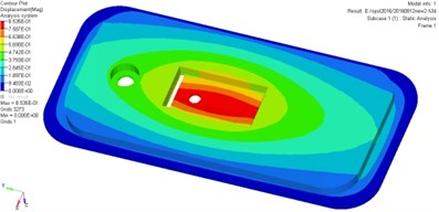
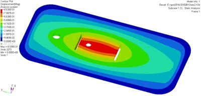
Fig. 9 shows the displacement contour of the door at different moments, the transition of color from blue to red represents the displacement changes from small to large.
As it can be seen from Fig. 9, the most severe serious deformation area locates in the middle part and the stiffened plate of the door. The maximum deformation of the door is less than 20 mm, indicating that the original model door body can meet safety requirements. According to the numerical simulation and performance analysis, the maximum misses stress is about 94.5 MPa, smaller than the material yield limit of 345 MPa, the maximum deformation is 0.85 mm, which does not exceed the limitation of damage failure and sealing failure. Meanwhile, the strength of the door meets the general technical requirements but the stiffened plate needs to be optimized.
Fig. 9Displacement contours for the original model
5. Structural design and topology optimization for the original model
5.1. Topology optimization
Topology optimization, a novel approach that can assist us to obtain the optimal material distribution or channel in a given design space, so as to meet the requirements of different performance or getting the lightest weight. Some commonly-used topological expression forms and interpolation methods are the homogenization method, density method, variable thickness method and topological function description method. In this study, the topology optimization method based on variable density method of continuum is applied for the original door optimization, meaning that in a given design space, it is necessary to discrete the cell density of retain part on the structure to 1 and the unwanted part to 0 after several topology optimization iterations [37]. The optimal material distribution scheme can be searched in an evenly distributed material designed by topology optimization.
As for the original door, topology optimization and shape optimization based on the variable density method were applied on purpose of decreasing the cost of the door as much as possible under the premise that anti-knock and sealing performance meet the safety requirements. It should be demanded that the minimum overall quality is the optimization objective and the limiting conditions are: the overall maximum stress < 345 MPa and the maximum displacement < 20 mm in the iterative calculation process. To achieve this aim, determining the design space is the first step, while the layout for strengthening ribs is decided by the original structure of the door. The reinforcing plate is the design space for topology optimization. Without considering the specific structure of the reinforcing plate on the inner edge, the design space for strengthening plate on back of the door is shown in Fig. 10, the topology optimization results based on element density distribution is shown in Fig. 11 (the density of red part is 1, and the density of green part is 0).
Fig. 10Design space for topology optimization
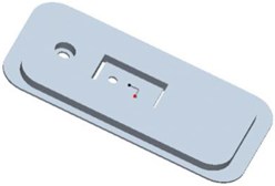
Fig. 11Element density distribution for topology optimization
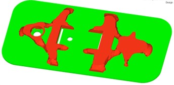
As it can be seen from Fig. 11, according to the topology optimization results, the number of strengthening ribs on the door body should be 2. Both the longitudinal and transverse reinforcing ribs play a connection and auxiliary role for the door. Considering the stiffened plate on the back of the door, the design space for topology optimization would make a difference. Namely, the structure of reinforcing plate on the back has already been identified, therefore it is unnecessary to consider the impact of force exerted on a structure in the topology optimization.
5.2. Static response for the optimization structure
Having finished the topology optimization and shape optimization of the original door, the new model is shown in Fig. 12. The distribution characteristics of stress field and displacement field of the new model are simulated, analyzed and compared with the original model.
The stress contour of the door is shown in Fig. 13, which indicates that the pressure is gradually increased from blue to red.
Fig. 12Geometry and mesh of new airtight blast door after structure design optimization

a) Geometry of the optimization model

b) Mesh of the optimization model
Fig. 13Stress contours for the optimization airtight blast door
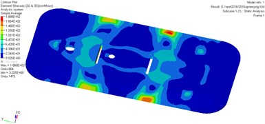
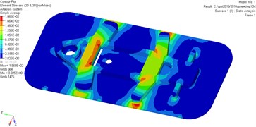
As it can be seen from Fig. 13, higher stress appears at the door while lower stress on the strengthening ribs of the door. The maximum stress is 186.8 MPa, influenced by the bolt connection and rigid connection, it is easy to generate stress concentration for the strengthening ribs. Therefore, the overall strength of the door would be affected by the strength of strengthening ribs.
The bolt should be rigid enough so as to meet the antiknock performance under gas explosion load in actual working conditions. Here, the safety factor defined as: , if such a factor of the door is less than 1, demonstrating that the structural strength of the door meet the requirements.
Fig. 14 shows the displacement contour of the door at different moments, the transition of color from blue to red represents the displacement changes from small to large.
Fig. 14Displacement contours for the optimization airtight blast door
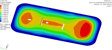
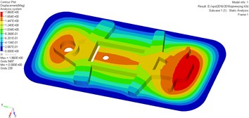
As it can be seen from Fig. 14, the deformation of the door reaches a maximum when the time arrives at a certain value. The most serious deformation part of the door locates in the bottom and the upper surface of the door. The maximum deformation of the door is greater than 20 mm, showing that the original model door body satisfies the corresponding safety requirements.
Results indicates that the maximum stress and maximum displacement of optimization model has increase by 97 % and 118 % compared with the original model under the same load, respectively. But the weight of the optimized door is less than the original one and its antiknock performance meets safety requirement for coal mine under the same load, as shown in Table 4.
Table 4Comparison of numerical results between the original model and optimization model
Structure | The maximum stress / MPa | The maximum displacement / mm | Mass / Kg |
Original model | 94.5 | 0.856 | 381.2 |
Optimization model | 186.8 | 1.86 | 276.7 |
However, under the real circumstances, the load work on the airtight blast door is a dynamic shock wave, the interaction between gas explosion shock wave and the door is a complicated process, the dynamic strain and stress need to be simulated in order to reveal the dynamic response of the door, hence, we will conduct a simulation using SPH particles to replace the gas explosion shock wave.
6. Dynamic response for the optimization model
6.1. Models and conditions
The SPH-FEM model of airtight blast door and the tunnel are established by ANSYS/LS-DYNA. The tunnel to be simulated is assumed as a semi-closed pipe model, and the corresponding size is described in Fig. 15(a). As it can be seen from the Fig. 15(b), SPH particles are established to simplify the explosion shock wave caused by gas explosion. The model is divided into two parts, part 1 (from A to B) consists of 4500 SPH particles to substitute the same gas explosion load induced by a length 28 m of methane/ air mixture and full of 200 m3 methane/air mixture with 9.5 % concentration [3]. However, in this work, we develop a new part 2 (from B to C), which includes the airtight blast door and shock wave transmission section.
Fig. 15Length and the cross-sectional area of the tunnel
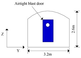
a) Cross-section of the tunnel

b) SPH equivalent model of tunnel and airtight blast door
Fig. 16Finite element mesh of the door and tunnel

a) Cross-section of the model

b) Mesh of FEM-SPH model
Taking the actual size of the model established above into account, the door hinge is described with rotatable elements mesh while the door shell is meshed with the mapping method and simulated using 163 element, each unit size is 0.01 m. The tunnel is meshed with hexahedral grid and simulated with 164 element. Grid of the door and the tunnel is shown in Fig. 16. Then related projects are submitted to LS-DYNA and the stress filed as well as displacement field are analyzed as below.
6.2. Stress field
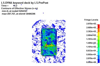
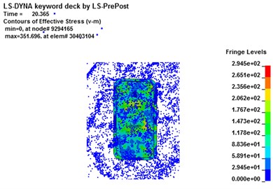
The stress contours of the door at different moments are shown in Fig. 17, which reveals that the pressure increases gradually from blue to red. The equivalent stress of the cabin door increases gradually as the shock wave propagates forward. Higher stress appears at the door while lower stress on the cabin door and emergency door during the whole process of SPH particles interact with the door.
Fig. 17Stress contour for the airtight blast door
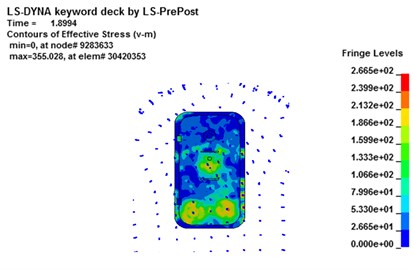
a) 1.89 ms
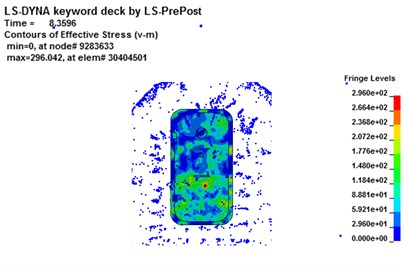
b) 8.36 ms
c) 15.2 ms
d) 20.3 ms
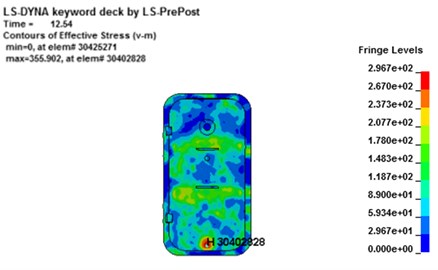
As it can be seen form Fig. 17, stress concentration appears at the impact face of the door. The maximum stress concentration appears at the bottom surface of the door. At the moment of 12.54 ms, the maximum stress on element 30402828 is 284 MPa, as shown in Fig. 18(a), but the maximum stress of the door does not surpass the material’s yield strength. The maximum deformation of the unit for the door is about 7.8 mm, as shown in Fig. 18(b). However, no obvious plastic deformation appears and the stress of elements at the other portions of the door does not exceed the material yield strength. When the overpressure of gas explosion reaches about 0.6 MPa, the strength of the overall structure and main parts are in the elastic range, illustrating that it does not reaches the yield stress and the deformation can recover. Because of the short time of explosive shock, stress concentration and plastic zone do not lead to the failure of the whole door.
Fig. 18Maximum stress result for the airtight blast door
a) Stress contour for the maximum stress element
b) The maximum stress element time history
6.3. Displacement field
Fig. 19 shows the displacement contour of the door at different moments, the transition of color from blue to red represents the displacement changes from small to large. Deformation on the impact face of door is the most obvious owing to be subjected to the explosion shock wave and the dynamic pressure directly. As the shock wave gradually propagates forward, the tunnel wall reflects shock wave and the displacement of the door increases owing to superimposed deformation and continuous force exerted by explosion blast wave.
Fig. 19Displacement contour for the airtight blast door
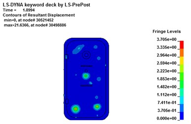
a) 1.89 ms
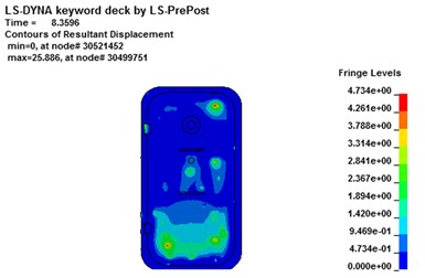
b) 8.36 ms
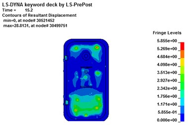
c) 15.2 ms
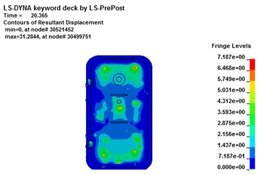
d) 20.3 ms
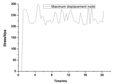
As it can be seen from Fig. 19, deformation of the node changes smoothly and the largest deformation emerges on the impact surface of the door. Finite element analysis results show that the displacement of node 30499751 reaches the maximum. The maximum absolute displacement value reaches about 7.89 mm at the moment of 20.14 ms, as shown in Fig. 20(a). The maximum displacement of element’s stress-time curve is extracted and the maximum stress value of the door is about 297 MPa, as shown in Fig. 20(b), illustrating that it does not reaches the yield stress and the deformation can recover. However, the absolute maximum displacement value of the door exceeds 20 mm and could guarantee the safety of the rescue according to code for design of mine rescue equipment.
According to the static and dynamic analysis of the optimization blast door, it could guarantee the safety requirement according to the code for design of mine rescue equipment and can be good for safety production. But the maximum displacement and maximum stress of the optimization model using FEM-SPH algorithm under dynamic load is about 3 times larger than those of the door under static load.
Fig. 20Maximum displacement result for the airtight blast door
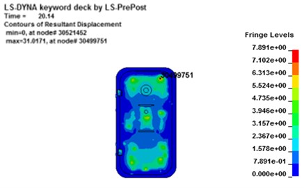
a) Displacement contour for the maximum displacement element
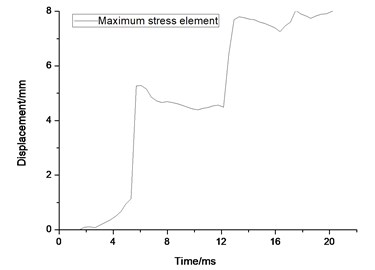
b) the maximum displacement element time history
7. Conclusions
A novel calculation approach-SPH-FEM contact algorithm is proposed in this paper in order to solve the contact problem between the SPH particles and the finite elements, such an algorithm lies on a meshless contact algorithm and can be applied to calculate the contact force between SPH particles and finite elements by adding the contact force by solving SPH momentum equations and FEM dynamic equations.
The static response and topology optimization of the original blast door were conducted using an approximate triangle shock wave based on ANSYS. Results showed that the performance indicators of the optimization airtight blast door meet the general technical requirements, and the structure is safe and reliable. Without weakening the explosion resistance capability, the weight of the new airtight blast door is 27.4 % less than the original model, and the cost decreases significantly. Therefore, the topology optimization and shape optimization techniques can substantially improve the performance of original development.
The FEM-SPH algorithm is employed to investigate the dynamic response of optimization model under gas explosion load, results showed that the detonation of SPH particles can be applied to replace the propagation of gas explosion shock wave. Mechanical response for the optimization blast door illustrated that the stress and deformation concentration of the former were similar to those of the latter one, maximum stress and maximum displacement of the optimization door under dynamic load with SPH algorithm is about 3 times larger than those of the door under static load.
This paper provides a comprehensive method considering the topology optimization and dynamic response of a structure based on topology method and FEM-SPH algorithm, which would provide a design thinking for structure analysis and performance evaluation of antiknock structures.
References
-
Wang K., Jiang S. H., Ma X. P., Wu Z. Y., et al. Study of the destruction of ventilation systems in coal mines due to gas explosions. Powder Technology, Vol. 286, 2015, p. 401-411.
-
Yin W. T., Fu G., Yuan S. S., et al. Study on basic characteristics and occurrence regularity of major gas explosion accidents in Chinese coal mines during 2001-2012. China Safety Science Journal, Vol. 23, Issue 2, 2013, p. 141-147.
-
Zhang B. Y., Zhao W., Wan W., Zhang X. H. Pressure characteristics and dynamic response of coal mine refuge chamber with underground gas explosion. Journal of Loss Prevention in the Process Industries, Vol. 30, 2014, p. 37-46.
-
Niu H. Y., Deng J., Zhou X. Q., Wang H. Q. Association analysis of emergency rescue and accident prevention in coal mine. Procedia Engineering, Vol. 43, 2012, p. 71-75.
-
Margolis K. A., Westerman C. Y., Kowalski Trakofler K.-M. Underground mine refuge chamber expectations training: program development and evaluation. Safety Science, Vol. 49, 2011, p. 522-530.
-
State Administration of Work Safety in China. The Notice about the Interim Provisions of System in Coal Mine Construction [EB/OL], 2011.
-
Mitchell M. D. Analysis of Underground Coal Mine Refuge Shelters. Ph.D. Thesis, West Virginia University, 2008.
-
Fan X. T. Study on blast performance of refuge chamber. Mining Safety and Environmental Protection, Vol. 37, Issue 3, 2010, p. 25-30.
-
Guo P. H., Jiao G. T., Han J. Anti-explosion performance and numerical simulation optimization of refuge chamber. Mechanical Engineering and Automation, Vol. 189, Issue 2, 2015, p. 96-97.
-
Zhu X. G., Zhang G. X., Jing T. T., Jiang D. X. Experimental study on sealing performance of protective sealing door for mine refuge chamber. Mining Safety and Environmental Protection, Vol. 40, Issue 4, 2013, p. 39-41.
-
Liu Z. C., Song W. Y., Ji W. T., Wen X. P. Experimental study on effects of explosion door mass on venting characteristics of gas deflagration. Journal of Thermal Science and Technology, Vol. 13, Issue 4, 2014, p. 359-364.
-
Wang Y. G., Yang H. J., Jiang H. Experimental study on the anti explosion shock wave of the protective door. The 8th Meeting of the Umbrella Figure Explosion Mechanics, Beijing, China, 2007.
-
He X., Pang W. B., Qu J. B., Liu G. J., et al. Protective door damaged by air shock wave and fragment arisen from explosion in prototype tunnel. Explosion and Shock Waves, Vol. 24, Issue 5, 2004, p. 475-479.
-
Gao N., Jin L. Z., You F., Wang L. Research and experiment on fireproof anti-explosion air tightness system of refuge haven in underground mine. Journal of China Coal Society, Vol. 37, Issue 1, 2012, p. 132-136.
-
Jing T. T. Research on Blast Airtight Door Key Technology of Refuge chamber. Master Thesis, Coal Science Research Institute, 2012.
-
Bo Z. G. Research on the anti explosion shock performance of the protective airtight door of the refuge chamber. Mining Safety and Environmental Protection, Vol. 39, Issue 6, 2012, p. 18-22.
-
Wang Z. L. Analysis of anti-explosion and anti-impact properties of protective sealing valve in refuge chamber. Coal Mine Safety, Vol. 44, Issue 8, 2013, p. 229-231.
-
Han H. R., Gao N., Wang Y. Research on protective door of permanent refuge haven in Changcun mine. Mineral Engineering Research, Vol. 31, Issue 2, 2016, p. 40-45.
-
Wu Y. T., Zha N., Gao Q. M., Fu Y. S. The safety of the blast-resistant doors using dynamic FEM analysis. Journal of Projectiles, Rockets, Missiles and Guidance, Vol. 27, Issue 2, 2007, p. 245-247.
-
An C. H. Finite element simulation analysis of self-recovery mine explosion door. Coal Mine Machinery, Vol. 34, Issue 8, 2013, p. 104-106.
-
Jing T., Zhang G. X., Zhu X. G. Structure design of protection secret door of mine refuge chamber. Mining Safety and Environmental Protection, Vol. 39, Issue 1, 2012, p. 40-45.
-
Luo X. N., Huang P., Qian X. M. Simulation analysis on structure safety of refuge chamber door under explosion load. Chinese Journal of High Pressure Physics, Vol. 27, Issue 6, 2012, p. 889-896.
-
Chang D. G., Gao X. J., Fei Z. Z., Li S. M. Impact analysis on blast airtight door of new mine refuge chamber. Journal of Mechanical and Electrical Engineering, Vol. 30, Issue 10, 2013, p. 1178-1181.
-
Guo D., Liu J. B., Zhang X. B. Resistance parameters analysis and dynamic response for a steel blast door subjected to blast loading. Journal of Vibration and Shock, Vol. 32, Issue 2, 2013, p. 134-140.
-
Li Z., Leducc, Combescureb A., Leboeuf F. Coupling of SPH-ALE method and finite element method for transient fluid-structure interaction. Computers and Fluids, Vol. 103, 2014, p. 6-17.
-
Nassiri A., Kinsey B. Numerical studies on high velocity impact welding: smoothed particle hydrodynamics (SPH) and arbitrary Lagrangian-Eulerian (ALE). Journal of Manufacturing Processes, Vol. 101, 2016, p. 1789-1802.
-
Oger G., Marrone S., Letouzé D., Deleffe M. SPH accuracy improvement through the combination of a quasi-Lagrangian shifting transport velocity and consistent ALE formalisms. Journal of Computational Physics, Vol. 313, 2016, p. 76-98.
-
Lucy L. B. A Numerical approach to the testing of the fission hypothesis. Astron, Vol. 82, 1977, p. 10-13.
-
Gingold R. A., Monaghan J. J. Smoothed particle hydrodynamics: theory and application to non-spherical stars. Monthly Notices of the Royal Astronomical Society, Vol. 181, 1997, p. 375-389.
-
Liberskty L. D., Petschek A. G., Carney T. C., et al. High strain Lagrangian hydrodynamics. Journal of Computational Physics, Vol. 199, 1991, p. 67-75.
-
Randles P. W., Libersky L. D. Smoothed particle hydrodynamics: some recent improvements and applications. Computer Methods in Applied Mechanics and Engineering, Vol. 139, 1996, p. 375-408.
-
Swegle J. W., Hicks D. L., Attaways W. Smoothed particle hydrodynamics stability analysis. Journal of Computational Physics, Vol. 116, 1995, p. 123-134.
-
Zhang Z. C., Qiang H. F., Gao W. R. A new coupled SPH-FEM algorithm and its application to impact dynamics simulation. Explosion and Shock Waves, Vol. 31, Issue 3, 2011, p. 243-249.
-
Cowper G. R., Symonds P. S. Strain-Hardening and Strain-Rate Effects in the Impact Loading of Cantilever Beams (No. TR C 11 28). Brown University, Providence RI, United States, 1957.
-
Zhao H. J., Qian X. M., Li J. Simulation analysis on structure safety of coal mine mobile refuge chamber under explosion load. Safety Science, Vol. 50, Issue 4, 2012, p. 674-678.
-
Technological Equipment Department of State Administration of Coal Mine Safety in China. Notice of Soliciting Comments on Modifying. Mine Portable Hardware Rescue Capsule General Technical Conditions (draft) [EB/OL], 2011.
-
Bendsøe M. P. Optimal shape design as a material distribution problem. Structure Optimization, Vol. 1, Issue 4, 1989, p. 193-202.
Cited by
About this article
This work is supported by National Natural Science Foundation (Grant No. 51504190 and No. 51604218), General program of National Natural Science Foundation (Grant No. 51674191 and No. 51674192), Scientific Research Program Funded by Shaanxi Provincial Education Department (Grant No. 2013JK0947), Postdoctoral Science Foundation of China (Grant No. 2013M530430), International Science and Technology Cooperation and Exchange of Shaanxi Province (Grant No. 2016KW-070), Postdoctoral Science Foundation of Xi’an University of Science and Technology (Grant No. 2016QDJ013 and No. 2015T81043).
Haitao Li conducted the simulation and wrote this manuscript. Xiaokun Chen put forward the theme and idea of this manuscript. Yutao Zhang revised the grammar of this manuscript. Qiuhong Wang edited the format of this manuscript. Jun Deng works presented a novel design for recue ball simulated in this manuscript.
