Abstract
In order to investigate the dynamic response and failure modes of concrete wall under hydraulic blasting load in underground tunnels, the fracture mechanism and zoning characteristics of hydraulic blasting of concrete wall was analyzed theoretically. Stress field, displacement field and energy variation laws of concrete wall has been simulated based on the finite element dynamic program LS/dyna. Meanwhile, different experimental conditions on the dynamite, reserved hole parameters such as demolition parameters are designed studied according to the blasting fracturing principle. The effects of stress wave, high pressure gas expansion effect in the dismantling process, application of line of least resistance principle and directional blasting effect control principle are analyzed. Results reveal the FSI effect between concrete wall and the water-dynamite-pore wall and the relationship between parameters of the structure and the dynamite dynamite, the concrete dynamic compressive strength and dynamic tensile strength. Numerical and experimental methods as well as conclusions will provide basis for the blasting demolition of brick concrete wall under similar conditions.
1. Introduction
At present, coal is still the most important energy in China. And there are plenty of coal in north and west China. However, the exploitation of coal in north and west China has led to the frequent occurrence of serious mine fire disasters. Among which, gas explosion and coal spontaneous combustion are the two main disasters for coal mine [1], In order to prevent the coal mine fire, many measures are widely used, such as ventilation by even air pressure, grouting the mud or three-phase foam, spraying inhibitor, injecting N2 or CO2, etc. [2-3]. However, it is necessary to close the working face in order to avoid gas explosion and coal fires happened in underground coal mine [4]. The sealing wall needs to be dismantled after the disasters are controlled, in order to ensure safety production for coal mine and control the disaster disasters effectively, the properties of materials masonry for sealing walls, especially the sealing and anti-knock performance should be strictly considered and selected. There is no doubt that it would increase the burden and difficulty for removal of the walls. On the one hand, there exists lots of methane with high concentration and other toxic and harmful gases in the enclosed area, thus posing a great threat to personal safety of those who dismantle the sealing [5]. On the other hand, the existing dismantling technologies for sealing in underground confined space is high-strength and time consuming, leads to a higher possibility for accident, it is difficult to meet the requirements for the safety operation. Therefore, it is imminent to develop a safe technology for dismantle the sealing wall in underground coal mine.
Up till now, the methods used for dismantling the walls at home and abroad mainly includes manual dismantling, static-silent blasting and expansion [6, 7]. Li [8] carried out a blasting experiment by using the SCA static silent blasting agent developed by Beijing Research Institute of architecture. Huo [9] and Zhang [10] applied the ZHLJ-3 type expansion agent to conduct a series of demolition experiments successfully on the ground. Wang [11] and Niu [12] dismantled a permanent sealing with Spray by a traditional explosion-proof tools such as Pratia, copper solder, pressure wind pipe and water pipe, however, such an approach is a waste of time though it is safe and reliable.
Therefore, it is necessary to develop new methods, equipments and technologies in order to meet the safety and operability of the demolition work and improve the efficiency of dismantle in such a high risk environment. In this paper, we establish a dismantling technology of concrete wall based on hydraulic blasting through theoretical analysis, numerical simulation and experiment, thus will providing basic parameters for the demolition technology of concrete walls in underground mine.
2. Fracture mechanism and zoning properties of concrete wall with hydraulic blasting load
2.1. The intensity factor of crack stress
The aim of fracture mechanics is to study the parameters of stress field, displacement field crack tip in seeking for control cracking materials, to analyze the fracture properties and criterion of material, which can provide reference significance for us to study formation process, propagation laws and criterion under explosion load. Making sure of the stretched form of crack is the first step to determine the crack propagation criterion. In fracture mechanics, in accordance with the crack location and its different forms, crack are summarized into 3 kinds: the open type (type I) under tensile force at vertical and fracture surface direction, the slide open type (type II) under shear force parallel to the fracture surface and perpendicular the crack tip line, the tearing type (type III) under the shear force parallel to the fracture surface and crack tip. In practical engineering applications, due to affected by complex forces and other factors such as material non-homogeneous, anisotropic, type I, type II and type III result in the force field of crack tip, such can be called for mixed mode crack.
After blast, there are two primary types of structural failure – first-excursion failure and cumulative plastic failure [13]. There exist two different functions: tensile wave and shear wave after the explosion of dynamite, due to tensile wave is larger than that of the shear wave numerically, tensile wave plays a leading role in the formation of crack. Therefore, the cracks generated by detonation gas are mostly type I. The stress intensity factors of crack tip can be obtained by the crack growth model and fracture mechanics. Macro-fracture generated by blast wave is affected by biaxial compression (σ1 is vertical stress, σ3 is horizontal stress), according to the crack propagation model in fracture mechanics (Fig. 1), where, β is the angle between crack and the maximum principal stress. a is the half of lengthof dynamite crack, m. The macro crack surface on X normal stress and shear stress value can be defined as follows [14]:
The corresponding stress intensity factor KI and KII of crack in Type Ⅰ and II can be deduced by the calculation method of crack tip in fracture mechanics:
The macroscopic crack formed by the explosion shock wave is a compound type, which is composed of an open type crack Ⅰ and a second sliding crack Ⅱ, the corresponding crack intensity factors are expressed as follows:
where, KI(1) is the stress intensity factor of type I crack under crustal stress, MPa1/2, KII(1) is the stress intensity factor of type II crack under crustal stress, MPa1/2.
Fig. 1Crack extension model under biaxial compression
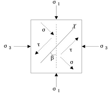
Fig. 2Crack propagation model derived by detonation gas
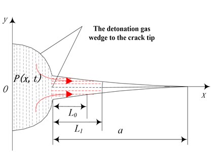
When the wall encounter a gas explosion, crack and wedge crack tip would be filled with high temperature and high pressure gas, once the stress intensity factor of the expansion gas at the crack tip is larger than that of the crack fracture toughness, crack extends further. The expansion type I of type II cracks under detonation gas is shown in Fig. 2. It is assumed that the decay process of gases pressure in the hole for P(T), gas pressure distribution along the length direction of the crack explosion P(x,t), Lt is the length of the wedge crack of gas explosion. The stress intensity factor at the crack tip under explosion gas is:
where, KI(2) is stress intensity factor of type I crack under explosion gas, MPa1/2, rb is the radius of hole, m. L0 is the length of initial crack after explosion, m.
As for the radius of hole is much smaller than the length of the crack, then Eq. (4) can be simplified as:
The crack in the wall is mainly type I, the stress intensity factor of type I crack under explosion and crustal stress is:
2.2. Propagation criterion for crack propagation of detonation gas
The condition of the radius of the crack zone continues to expand is that the stress intensity factor of the detonation gas in the crack tip is larger than the fracture toughness of the crack. Assume that Pb is pressure of detonation gas, the stress intensity factor of crack tip along the radius direction of the blasting gas is extended as below:
If the dynamic fracture toughness of the wall is KDIC, the steady state expansion condition of crack growth is:
2.3. Zoning characteristics of blasting induced cracking
The difference of the effect of dynamite on concrete wall will arouse corresponding broken types in the blasting body. When the explosion load on the borehole is much larger than the dynamic compressive strength of the wall, media around the dynamite will be crushed, thus forming a cavity and crush zone. Explosion shock wave and stress wave in crushing medium will decay quickly and exponentially, so the radius of explosion cavity and crushing zone is rather smaller. In the fracture zone, the stress wave and quasi-static pressure of detonation gas continue to decay into elastic wave, thus causing the elastic vibration of the particle, but not the further expansion of the crack. This area is called the elastic vibration area or the vibration area. The explosion action is finally formed in the medium as shown in Fig. 3.
Fig. 3Schematic diagram of blasting effect: 1 – enlarged cavity, 2 – crushing zone, 3 – fracture zone, 4 – seismic zone
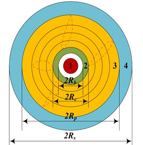
The crushed zone and fracture zone generated by the influence of dynamite explosion on the wall is characterized by the significant stress value σi are mainly related to the stress value of the medium. The criteria for the formation of the various regions can be divided according to the Mises criteria, the conditions of the formation of the crushed zone and the fracture zone are as follows, respectively:
where, σcd is the uniaxial dynamic compressive strength of concrete wall, MPa. σtd is the dynamic tensile strength of concrete wall, MPa.
3. Dynamic response of concrete wall under hydraulic blasting load
The blasting crack of concrete wall is related to the amount of dynamite, quantity of water, drilling parameters and physical mechanical properties of concrete. As for the water pressure blasting pre-crack of concrete wall, the relation between the amount of dynamite and the damage area is obtained by numerical simulation and theoretical analysis, which can be used for the optimization of blasting parameters of the wall.
3.1. Governing equations and computational methods
The water pressure blasting is a very short process, however, the mechanics problem involved is very complex, it is difficult and dangerous to test the experiment in a laboratory, and it is complicate to measure the explosion load. Nonlinear finite element program LS-DYNA can be employed to simulate the whole process of shock wave propagation and the transient response of the structure.
Lagrangian is considered as the main algorithm to describe the incremental method in ANSYS/LS-DYNA 3D program [15]. The coordinate of the particle at the initial moment is Xi (i= 1, 2, 3), at any time t, The coordinates of the particle comes to xi (i= 1, 2, 3); Then the motion equation of this particle can be described as:
When t=0, the initial conditions are:
where, Vi is the initial velocity.
3.1.1. Momentum equation
In the continuum mechanics, momentum equation is:
where σij,j one order partial derivative of Cauchy stress component σij with respect to the coordinate variable in the jth direction, fi is the volume force vector of unit mass, xi is acceleration vector, and ρ is the density of air.
3.1.2. Conversation equation
Conversation equation of mass is:
where ρ is the current density of air, ρ0 is the initial density of air, J=|∂xi/∂xj| is the relative volume, xi is the space coordinate in the ith direction, xj is the matter coordinate in the jth direction, and ∂xi/∂xj is the strain gradient with respect to xj.
3.1.3. Energy equation
Energy equation is:
This equation is mainly used for the equation of state and calculations for the balance of total energy, where V is volume, εij is strain rate tensor, q is volume viscous resistance and p is hydrodynamic pressure.
However, the expression between deviatoric stress tensor and hydrodynamic pressure is given by:
ANSYS/LS-DYNA is a finite element computation code for dynamics suitable for impact, explosion and other instantaneous problems, is used to carry out the numerical simulation process. In LS-DYNA, there are three classes of methods are available for generating the grids and mesh, include Euler, Lagrange and Arbitrary Lagrange-Euler (ALE) method, Details of the models of fluid-solid interaction can be found in the LS-DYNA theoretical manual [16]. In this study, the ALE method is employed to simulate the process of the methane explosion, the propagation of air shock waves through tunnel in this process, and the interaction of explosion shock waves with the sealing wall [17]. Wang researches the shock wave propagation process and analyses the seismic effects of shallow underground explosions [18].
The ALE algorithm consists of a classical Lagrange step in which the mesh moves along with the modeled material, a rezone step in which the mesh is modified to preserve good quality through the computation of Euler time step, and a remapping step in which the solution is conservatively transferred from the old mesh to the new rezoned one, and thereby analysis for the fluid-solid coupling transient.
3.2. Equations and mechanical parameters
The model is composed of 5 kinds of materials, including dynamite, water, air, concrete, among which dynamite, water and air, are constructed by using Eulerian mesh. In the model, multi-material ALE algorithm is applied to describe the element, Lagrange grid is adopt to mimic concrete.
3.2.1. Shock tube
The dynamite device is made of high strength alloy steel, MAT_JOHNSON_COOK* is selected to describe material, the state equation *EOS_GRUNEISNE. is defined as below [19]:
where, ¯εp is equivalent plastic strain. ε'* is dimensionless plasticity ratio of ε'0=1.0s-1. ε'*=¯εp/ε'0; T* is relative temperature, T*=(T-Troom)/(Tmelt-Troom); A is yield stress, Pa; B is strain hardening coefficient. n is strain hardening index. C is strain rate correlation coefficient. m is temperature correlation coefficient. Specific parameters see in Table 1.
Table 1Material parameters of shock tube
Parameters | RA | ρ | c | MT | A | B | n | C | m |
Value | F-94 | 7.89 g/cm3 | 452 J/kg·K | 1811 | 350 MPa | 275 MPa | 0.36 | 0.022 | 1.0 |
3.2.2. Dynamite
High energy dynamite materials is applied to describe TNT dynamite, JWL state equation is applied to describe the expansion of detonation product, it is assumed to detonation product propagate at constant velocity and the before detonation. Equation of state JWL is defined as follows [20]:
where, P is pressure, V is the relative volume, e is the internal energy of the unit volume of dynamite, A, B, R1, R2 and ω are the constant in laboratory. Parameters in the calculation Eq. (19) are shown in Table 2.
Table 2Material parameters of dynamite
Parameters | ρ | D | PCJ | A | B | R1 | R2 | ω |
Value | 1.631g/cm3 | 6717m/s | 18.5Gpa | 540.9Gpa | 9.373Gpa | 4.5 | 1.1 | 0.35 |
3.2.3. Water
Liquid water is selected as the blasting medium, water is defined as empty material model (*MAT-NULL), and equation of state for water is described by Gruneisne [21]:
The equation of state for the expansion material is [22]:
where, ρ0 is the initial density of the water, C is the intercept of the curve VS-VP, namely the propagation velocity of shock wave in water υ is Poisson’s ratio; S1, S2 and S3 are the coefficients of the intercept of the curve VS-VP. γ0 is Gruneisen coefficient; α is the first order volume correction for γ0 and μ=ρ/ρ0-1. E is the internal energy per unit mass. Material parameters are shown in Table 3.
Table 3Material parameters of water
Parameters | ρ0 | υ | C (cm/us) | S1 | S2 | S3 | γ0 | α | E (Mbar) | V0 |
Value | 1.0 g/cm3 | 8.9e-4 | 0.1647 | 2.56 | 1.986 | 1.227 | 0.0 | 0.5 | 0.0 | 1.0 |
3.2.4. Concrete wall
Concrete is the mainly material of sealing wall, JOHNSON_HOLMQUIST_CONCRETE is selected as the constitutive model, called model JHC, which can be used to simulate the damage behavior under high strain rate, large deformation and high impact strength of brittle materials such as concrete. The continuous damage degradation effect of material strength is increased based on the JH-1 model, which can be applied to describe the failure process of brittle materials with load. During the loading process in the experiment, the material is elastic, before stress reaches the yield limit. With the accumulation of damage, the material begins to deteriorate until it is completely broken. The theoretical formula of JHC constitutive model is shown as follows:
where, σ*i is the standard full strength, σ*f is standard failure strength, D is damage factor, and 0≤D≤1; σHELk is Hugoniot elastic limit stress, Δεp is material plastic strain, εfp is constant pressure damage plastic strain under standard pressure p, A, B, C, M, N, are constants of material. p* is standard pressure. ˙ε* is real time strain rate of reference strain rate 1 s-1. K1, K2, K3 are constant. ρ is real-time density; ρ0 is initial density. Material parameters of concrete wall are shown in Table 4.
Table 4The material parameters of concrete wall
Parameters | ρ | E | u | G | A | B | C | M | N | ε |
Value | 3.163 Kg/m3 | 72 GPa | 0.22 | 40 GPa | 0.93 | 0.1 | 0.003 | 0.35 | 0.77 | 1 s-1 |
Parameters | T | σfmax | HEL | PHEL | D1 | D2 | K1 | K2 | K3 | |
Value | 0.15 GPa | 0.5 | 5.95 GPa | 2.92 GPa | 0.053 | 0.85 | 45.4 | 45.4 | 45.4 |
3.3. Physical and numerical models
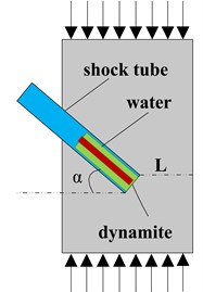
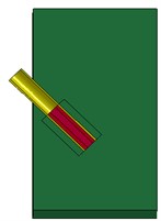
In this paper, the conventional closed wall is applied as the research object for hydraulic blasting simulation, see Fig. 4. As can be seen from Fig. 4, the cross section of sealing wall is 3.2×2.6 m, slotting on both left and right sides, constraints to roof and floor. The thickness of wall is 1.5 m, according to the confined concrete thickness, section and specify the degree of fragmentation, as for the experience formulas Q1=K1(K2δ)1.4R1.6 and Q2=KσeδV2/3 [23] and a number of domestic hydraulic blasting engineering comparison basis, the positive blasting hole length is designed for 1 m. The dynamite is chosen as cube dynamite, overall initiation, arranged in the center position at 0.5 m, and the dynamite length is 0.03 m. Separating and common nodes are used to establish the model.
Fig. 4Physical model of water pressure blasting of concrete wall
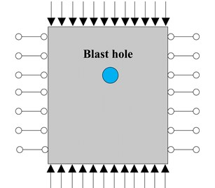
a) The front view
b) The profile
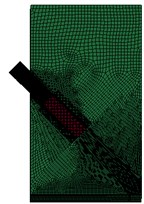
Unit for the model is cm-g-µs, of which height, width and thickness are 100 cm, 70 cm, 50 cm, respectively. The diameter of the hole and shock tube are 5 cm and 1 cm, respectively. The model is meshed with the mapped mesh method and hexahedral mesh. Combined with the actual situation of coal mine, the model is constrained on the X direction on positive face, Y direction on the top and the bottom surface, the two sides are set with no reflection boundaries, no constraint on the front and back faces. Solution time is set to 500 s, output per 20 s. As for the symmetry of the structure, the time and period for simulation, 1/2 of the solid model is established, the numerical model and grid are shown in Fig. 5.
Fig. 5Mesh and numerical model of hydraulic blasting in closed wall
3.4. Test results and discussion
3.4.1. Fluid-structure interaction effect
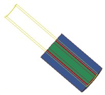
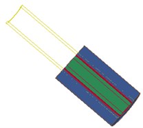
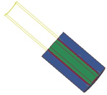
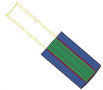
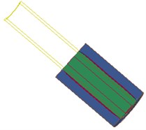
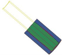
Fig. 6 shows the interaction between the shock wave and the hole wall in the blasting hole, which shows that the explosion field and the pore wall are mutually restricted and influenced. As the dynamite explode, detonation products expansion occurs, at the same time, on the one hand, energy is absorbed by water in the inner hole and began to spread around rapidly, on the other hand, high temperature and high pressure gas diffuse in high-speed after the explosion.
Fig. 6Fluid-structure coupling effect of water – dynamite – pore wall
a) 0 µs
b) 30.8 µs
c) 39.6 µs
d) 60 µs
e) 180 µs
f) 279.2 µs
As can be seen from the Fig. 6, in the stage 0-40 µs, the blasting hole is destroyed sharply under the blasting stress wave, and tends to be stabilized gradually, which can be explained as follows: (1) Blasting holes squeezed by shock tube. (2) The strength parameters of the wall is far less than that of the shock tube shock. (3) Energy absorbed by wall is much larger than that of blast hole after detonation of shock tube. Therefore, pressure wave generated quickly through the water impact hole wall with the help of energy of dynamite in the shock tube, thus causing cracks of the hole wall, and the stress wave in the medium. Radial and tangential stress produced as the propagation of stress wave in the medium, and the tensile strength of the whole wall is far lower than the compressive strength, shear strength is also much smaller than the compressive strength. Meanwhile, high pressure gas produced equipment acts on the internal water in the detonating device, and propagates along the two directions before and after through the reserved hole at the bottom of the pressure relief port, directly work on the hole wall, therefore, hole wall damage increases rapidly in the initial stage and tends to be stable gradually.
3.4.2. Dynamic response of the wall under blast load
3.4.2.1. Stress field
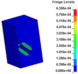
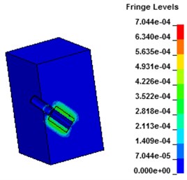
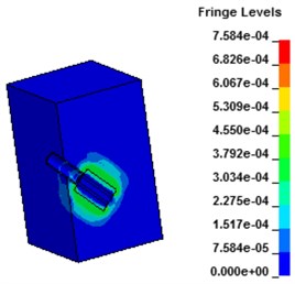
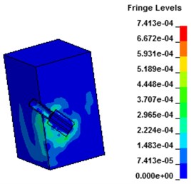
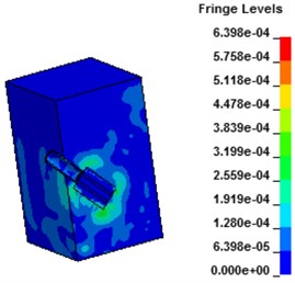
Fig. 7 shows the stress contours of the wall under hydraulic blasting, as can be seen from the figure, with the interaction between the explosion shock wave and the sealing wall, equivalent stress of the wall increased gradually at first and tended to balance thereafter. At the moment of 30 μs after the explosion, the water absorbs energy of the shock wave and begins to act on the hole wall. After 40 μs, the shock wave penetrates the shock tube and begins to spread to the wall. After that, the wall starts to crack and expands, and the stress increases gradually. Due to the action of the crack tip, stress increases to a certain degree tend to a balance.
Fig. 7Stress contours of concrete wall with hydraulic blasting load
a) 30.8 μs
b) 39.6 μs
c) 60 μs
d) 180 μs
e) 279.2 μs
3.4.2.2. Displacement field
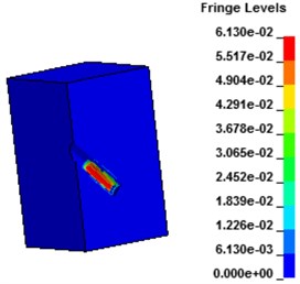
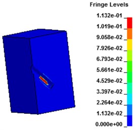
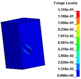
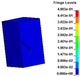
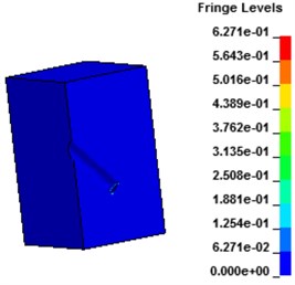
Fig. 9 shows the displacement contours under hydraulic blasting. As can be seen from the figure, with the interaction between dynamite shock wave and hole wall, deformation of hole wall increased gradually until failure occurs, cracks expanded from the hole wall around to the whole wall.
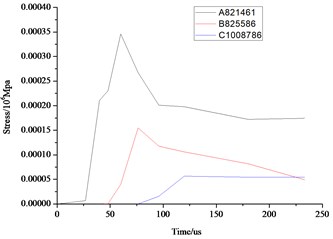
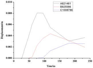
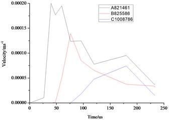
As can be seen from the above Fig. 10 and Fig. 11, the distance farther away from the hole, the smaller the stress, velocity, displacement. Due to the existence of the transmission, the further point has the hysteresis, the time of 3 elements reaches the maximum value are also different. Displacement, velocity and stress of all elements decrease rapidly, and the displacement, stress and vibration velocity attenuation are very small when the elements are close to the wall.
Fig. 8Monitoring elements concrete wall with hydraulic blasting load
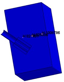
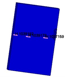
Fig. 9Displacement contours of concrete wall with hydraulic blasting load
a) 30.8 μs
b) 39.6 μs
c) 60 μs
d) 180 μs
e) 279.2 μs
3.4.3. Laws of energy variation
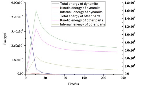
Fig. 12 shows the time-energy curves of the kinetic energy, internal energy and total energy of the wall.
As can be seen from the Fig. 12, energy in the whole blasting process includes 4 following aspects: (1) The crushing and plastic flow of medium. (2) Shock waves, elastic deformation of medium particle. (3) Gas product in medium broken to release into the air from air shock wave in the blasting process. (4) Crushing and throwing flying of the medium. The above four aspects, the crushing and throwing of medium is a hard (with the exception of a few unnecessary throw), the other is useless work. Blasting of shock tube will not work on the wall of the hole and caused excessive grinding. Energy produced by shock tube is consumed in the elastic deformation, wall breaking and cracking, throwing of medium. Therefore, the sum of total energy of the wall and the shock tube and water is much less than the total energy of the dynamite after the explosion.
Fig. 10Comparison of the stress, displacement and velocity of the different elements in the middle section of the wall
a) Stress
b) Displacement
c) Velocity
Fig. 11Comparison of the stress, displacement and velocity of the different elements in the front face of the wall
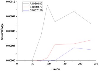
a) Stress
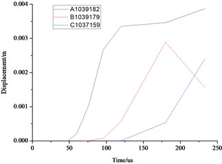
b) Displacement
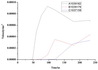
c) Velocity
Fig. 12Energy variation laws of concrete wall with hydraulic blasting load
4. Experimental tests on the ground
4.1. Experimental device
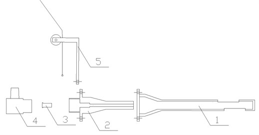
The whole structures of the lasting device can be divided into three parts: the base device, the dynamite device, and safety protection pad. The basic device is composed of an exciter, a base, a shock tube, a guide and a pull rope. The overall schematic diagram of the physical blasting equipment is shown in Fig. 13.
Fig. 13The schematic diagram of blasting device: 1 – explosion guide device; 2 – base; 3 – shock tube; 4 – excitation device; 5 – guiding device
4.2. Experimental program
According to the construction materials and methods of the underground sealing wall, 5 walls are established in this experiment, 3 brick walls and 2 concrete walls. The height, width and thickness of each wall are 1.5 m, 1.5 m and 0.5 m, respectively. In order to simulate the blasting effect of sealing wall and test the performance of physical blasting equipment, strength grade of brick and cement mortar are MU20 and M20 respectively, C30 is selected for concrete wall.
The reserved hole should be designed on the sealing wall, parameters should be determined according to the thickness and strength of the closed wall, and the length of the general reserved hole in the horizontal plane is 2/3-3/4. The diameter of detonating device is 48 mm, according to the analysis above, reserved hole with diameter of 50 mm on the positive surface of wall, angle between the reserved hole and the front wall is 45, the difference L from bottom of the hole to the back face of the wall should be set differently. The design parameters and main breaking parameters of each working condition are shown in Table 5.
Table 5Element parameters of wall and blasting demolition
Number | Material | Compressive strength / MPa | L / cm |
1# | Concrete | 20 | 15 |
2# | Brick, cement mortar | 20 | 15 |
3# | Concrete | 30 | 15 |
4# | Concrete | 30 | 15 |
5# | Brick, cement mortar | 20 | 15 |
4.3. Results and discussion
4.3.1. Failure modes
The results of the experiment are shown in Table 6.
Table 6Experimental results and description of each working condition
Program 1 | Program 2 | Program 3 | Program 4 | Program 5 | |
Front face | 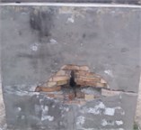 | 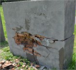 | 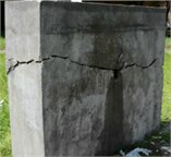 | 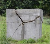 | 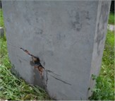 |
Back face | 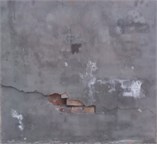 | 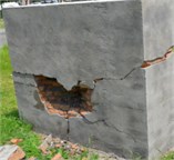 | 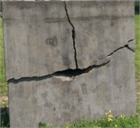 | 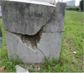 | 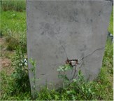 |
Description | The maximum length in horizontal direction is 72 cm, the maximum Vertical distance is 32 cm, the maximum depth is 20 cm; safety distance is 20 meters; no noise, no dust and no vibration | Blasting diameter is 70 cm, the depth is 20 cm, the maximum depth on back face is the formation is 18 cm, maximum horizontal length is 70 cm, the maximum vertical distance is 40 cm, safety distance is 1.7 meters | No blasting funnel, and the cracks transverse through the entire wall, the wall is divided into two parts, and the upper part wall is divided into about two parts by vertical crack | No blasting funnel, irregular blasting crater occur on the back, the maximum depth is 17 cm, the horizontal length is 75 cm, vertical distance is 35 cm. noise is 78.9 dB | The diameter of blasting funnel on front face is the 15 cm, no blasting funnel on the back face, noise is 86.1 dB, 11.39 ppm CO, the effect is not ideal |
4.3.2. The blasting demolition process
When the shock tube is excited, pressure generated in the tube will penetrate quickly wave through the water first to hole wall, resulting in the initial cracking of the hole wall, and stimulate the stress wave in the medium. Radial and tangential stress produced by stress wave in the medium, the tensile strength of the wall body is far lower than the compressive strength, shear strength is also much smaller than the compressive strength. Therefore, when the radial stress is larger than the dynamic compressive strength of the medium, the medium will be destroyed. When the tangential tensile stress is larger than the dynamic tensile strength of the medium, fracture will form.
At the same time, high pressure expansion gas produce in the device, act on the detonating device in internal water, transfer through the reserved hole at the bottom of the pressure relief port along the two directions, directly to the hole wall, forcing water to seep into the crack, cracking form into cracks, change into the stress concentration area of crack tip. When the stress intensity factor of fracture is larger than concrete has been blasting the fracture toughness of the medium, cracks will continue to extend. When the forward extension of the development of cracks encountered the free surface of the wall, the wall will be broken, the medium throwing under high pressure gas. When the stress wave is larger than the dynamic tensile strength of the wall, the reflection of the tensile wave is larger than that of the wall.
4.3.3. Difference
The blasting effect is closely related to the structure material and the strength of the wall. In the same condition of blasting parameters, experiment 3-5 and experiment 2 are designed with brick and concrete, and the breaking effect was different. Blasting effect, parameters and loading are related to the experiment 2 when compared with the experimental 1, difference in value L is only 3 cm, not only broken funnel in the back of the wall, but also the blasting effect is not inferior to the positive. In experiment 2, the quantity of dynamite is larger, and the width of crack is larger. But if the broken parameter is not reasonable, difference in the effect of blasting the wall before and after the demolition will be great.
Fig. 14The minimum resistance line of the wall to be demolished
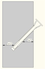
In experiment 1, according to the characteristics of the equipment and blasting design, the front and back of the wall are free surface. Reserved hole on the bottom of the front wall and the back distance are far from inconsistent. The distance form pressure relief mouth position on the detonating device to the free surface is different, the distance from bottom of the reserved hole to the two minimum resist line is different and the difference between the two line of least resistance is rather larger, according to the principle of directional blasting control, we can draw the conclusion that the blasting effect of front face on the wall is much better than that of the back face. Due to the reserved hole on the front face of wall, so it weakens the strength to a large extent, leads to the failure of formation of blasting funnel. Fig. 14 shows the 2 minimum resistance lines of wall.
In experiment 2, blasting parameters are improved compared with the experiment 1, reduce the reserved hole bottom distance away from the back of the wall, decrease the difference between the two line of least resistance, and therefore strengthen the blasting effect of the back of wall. Blasting funnel forms on the front and back of the wall, the demolition effect is more ideal, so the design of the blasting parameters of experiment 2 is reasonable.
The blasting parameters of experiment 2 and experiment 3 are identical, but due to the wall is made up of high strength concrete, the wall is separated by the formation of obvious cracks in the but not throwing.
4.3.4. Damage range
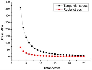
When the hydraulic shock tube in the medium of blasting, stress wave generated at first, parameters of medium on the wave front will not be mutation when affected by the impact of waves, but elastic deformation and destruction by using blasted medium will occur on concrete wall. Water pressure blasting device requires a reserved hole with radius of 2.5 cm, 500 MPa pressure peak on the hole wall according to the experimental dose. The Poisson's ratio of concrete and brick is 0.2. The radial stress and tangential tensile stress of the stress wave in different distance from the blasting holes are shown in Fig. 15.
As can be seen from Fig. 15, the large the distance away from the hole wall, with the increase of the distance away from the dynamite center, radial stress and shear stress are decreased exponentially. The smaller the ratio, of the distance, the larger attenuation of the stress is. Radial stress and shear stress will increase at the same position in the medium. At the same pressure peak value, radial stress should be larger than the tangential stress at different distance away from the dynamite center.
Fig. 15Radial stress and tangential stress at different distances
4.3.5. Crack range
When the radial stress is larger than the dynamic compressive strength of the material, the radial stress is higher than that of the material. When the tangential tensile stress is larger than the tensile strength of the material, the radial fracture is formed. The stress wave damage can be determined according to the Eq. (27) [24]:
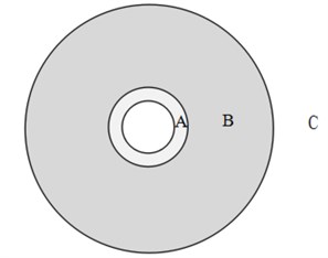
As for the calculating result and analysis above, the radial stress of hole wall is larger than the dynamic compressive strength of medium, radial stress in the distance to hole wall 0.8 cm generated at is equal to the dynamic compressive strength of medium, tangential stress away from the hole wall 7 cm is larger than dynamic tensile strength of concrete. Therefore, the medium in the range of 0.8 cm from the hole wall may be damage when subjected to compressive load, the maximum length of 3.7 cm of cracks will form.
At the same time when the formation of radial cracks, high pressure expansion gas act on water, force water seep into the fracture, the fracture bursting crack forms, change into crack tip stress concentration area. When the stress intensity factor of fractured ends is larger than the burst fracture toughness of medium, the gap will continue to extend and expand. Due to the water is selected as broken medium for blasting device, so gas pressure drops slowly in the whole process of gas expansion, water is pressed into the cracks, extend the length of the crack. According to the observation result of cracks in the wall, the maximum length of crack is larger than 72 cm. According to the above analysis, the range of hydraulic blasting damage is shown in Fig. 13.
In Fig. 16, the maximum distance from crushing zone formed in blasting medium to the hole wall is 0.8 cm. B is radial crack area of stress wave, maximum distance to the center hole is 7 cm. C is crack zone under high-pressure gas extension. The length can be larger than 72 cm in the experiment. Its action sphere and the experiment have a smaller difference. At the same time, scopes of stress wave and expansion gas and consistent with hydraulic blasting theory, indicating that the reasonable calculation can provide a theoretical method for the following parameters design and blasting process of in-depth study.
Fig. 16Damage range of non-dynamite blasting
4.3.6. The effect of reflected wave
The wave impedance can be calculated according to the density of medium and the velocity of longitudinal wave. Generally speaking, the density and velocity of concrete are 2400 kg/m3 and 4000 m/s, respectively, for air are 1.205 kg/m3 and 340 m/s. Wave impedance is significantly larger than that of air. When the stress wave transmits in concrete to spread in the air, the reflection wave will be tensile wave. The value of reflected can be calculated through the above data and the formula. When initial pressure of the hole wall is 500 MPa, the reflection Paula stress is 11.61 MPa 20 cm away from the explosion center. Because the reflected tensile wave stress is less than the dynamic tensile strength of the medium, the falling phenomenon of the wall surface will not occur, which is in accordance with the experimental result of concrete blasting.
Fig. 17The procedure and blasting effect on underground mine
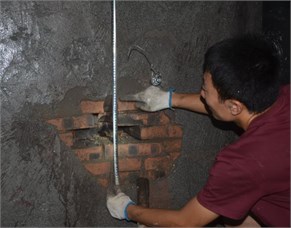
As for the brick masonry walls, stress wave affect as well, gas expansion and the reflection of tensile wave effect. Due to the particularity of the experimental architecture, the brick wall can be seen as a whole. Compared with concrete wall, the compressive tensile strength of brick is small, so the formation of the broken area is larger, more cracks in the fracture zone, the crack is wider, and the front and rear surfaces can form a better blasting funnel.
5. Experimental test on an underground mine
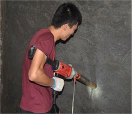
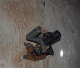
In order to check out the numerical simulation and similar experiment described above, we conducted an experiment on the underground mine, as described in Fig. 17.
As is can be seen from Fig. 17, compared with the results of numerical simulation and experiment on the ground, the maximum length of crack generates on the surface of the wall as long as 30 cm under the same amount of dynamite, which is of great significance for dismantling of the wall.
6. Conclusions
1) The conditions of the formation of the crushing zone and the fracture zone are divided according to the Mises criteria. The expression of the stress intensity factor of the crack under blasting load is defined. Under hydraulic blasting load, the destruction of medium is caused by two effects, the one is the blasting stress wave and another is quasi static high pressure gas expansion, among which the interaction between high-pressure gas of the quasi-static expansion plays a dominant role. Finite length cracks around the hole wall by blasting stress wave, quasi static high pressure gas expansion effect of continuous extend forward, and finally arrived at the free surface, medium crushing and throwing.
2) The dynamic model of hydraulic blasting demolition of sealing wall is established and the corresponding boundary conditions are determined, and the state equation and parameters of each material are defined.
3) The flow-solid coupling mechanism between wall and shock tube is revealed based on the ALE algorithm, dynamic mechanical response of wall under hydraulic blasting load is obtained, variation laws of displacement and velocity at different test points has been deduced.
4) The crack formation mechanism of the wall under hydraulic blasting load is explained by experiments. The effect of stress wave and the expansion of high pressure gas in the process of blasting demolition are analyzed. The results of the three experiments were analyzed by using the principle of minimum resistance line and the control principle of multi directional blasting.
5) The radial stress and shear to tensile stress at different distance of hole wall are calculated, the calculation method of concrete dynamic compressive strength and dynamic tensile strength are determined, dynamic compressive strength and dynamic tensile strength of concrete is obtained. The medium crushing zone and radial fissure scope of the stretch reflex are determined according to the maximum tensile stress theory.
References
-
Wang K., Jiang S. H., Ma X. P., et al. Study of the destruction of ventilation systems in coal mines due to gas explosions. Powder Technology, Vol. 286, 2015, p. 401-411.
-
Xu Y. L., Wang L. Y., Chu T. X., et al. Suspension mechanism and application of sand-suspended slurry for coal mine fire prevention. International Journal of Mining Science and Technology, Vol. 24, 2014, p. 649-656.
-
Qin B. T., Lu Y., Li Y., et al. Aqueous three-phase foam supported by fly ash for coal spontaneous combustion prevention and control. Advanced Powder Technology, Vol. 25, 2014, p. 1527-1533.
-
Teng B., Jiang F. X., Mo Z. N., Li X., Wu H. G. Discussion on technical standard of mine flame proof seal dam. Coal Science and Technology, Vol. 35, Issue 2, 2007, p. 97-99.
-
Yu L. The practice of Tucheng Mine while pumping gas in the closed side. Hydraulic Coal Mining and Pipeline Transportation, Vol. 3, 2012, p. 44-45.
-
Huang B. X., Liu C. Y., Fu J. H., et al. Hydraulic fracturing after water pressure control blasting for increased fracturing. International Journal of Rock Mechanics and Mining Sciences, Vol. 48, 2011, p. 976-983.
-
Huang B. X., Li P. F., Ma J., et al. Experimental investigation on the basic law of hydraulic fracturing after water pressure control blasting. Rock Mechanics and Rock Engineering. Vol. 47, 2014, p. 1321-1334.
-
Li Z. S. Application of static silent blasting agent in underground break down and tunnel through. Coal Mine Safety, Vol. 10, 1989, p. 20-21.
-
Huo J. J. Experimental study on the ventilation and sealing by the method of expanding and splitting. Mining Safety and Environmental Protection, Vol. 29, 2002, p. 17-18.
-
Zhang Z. G., Zhao W. M. Experimental study on the ventilation and sealing by the method of expanding and splitting. Science and Technology of Datong Coal Mining Administration, Vol. 96, Issue 2, 2003, p. 31-32.
-
Wang D. Y. Analysis of gas accumulation state and emission technology in mine blind lane. Development of Gas Geology and Gas Control, Vol. 8, 2007, p. 259-261.
-
Niu Z. J. The practice of Tucheng Mine while pumping gas in the closed side. Discussion on Gas Accumulation State and Emission Technology in Mine Blind Lane, Vol. 96, Issue 2, 2013, p. 226.
-
Zhao M. S., Huang D., Cao M. S., Chi E. A., Liu J., Kang Q. An energy-based safety evaluation index of blast vibration. Shock and Vibration, Vol. 2015, 2015, p. 9.
-
Ngidi S., Boshoff P. Cave management and secondary breaking practices at Palabora Mining Company. Journal of the South African Institute of Mining and Metallurgy, Vol. 107, Issue 12, 2007, p. 783-789.
-
Zhang Y. B., Chen C., Zhang Y. P. Numerical simulation study on hydraulic blasting based on LS-DYNA. Applied Mechanics and Materials, Vols. 170-173, 2012, p. 3245-3249.
-
Hallquist J. O. LS-DYNA Theoretical Manual. Livermore Software Technology Corporation, Livermore, 1998.
-
LS-DYNA Keyword User’s Manual (Version 971). Livermore Software Technology Corporation, California, 2011.
-
Wang I. T. Numerical analysis and experimental measurements of the ground vibration characteristics caused by shallow underground explosion. Journal of Vibroengineering, Vol. 18, Issue 1, 2016, p. 305-314.
-
Liu T. S. Study on quickly making dry-well by hydraulic blast. Proceedings of the 2003 International Autumn Seminar on Propellants, Dynamites and Pyrotechnics – Theory and Practice of Energetic Materials, Vol. 5, 2003, p. 624-629.
-
Su D. F., Kang Y., Li D. Y., Wang X. C., Yan F. W. Analysis and numerical simulation on the reduction effect of stress waves caused by water jet slotting near blasting source. Shock and Vibration, Vol. 2016, 2016, p. 18.
-
Yan Z. X., Jiang P., Wang H. Y. Study and handling on the safety of water pressure blast of cisterns. Advanced Materials Research, Vols. 433-440, 2012, p. 1271-1274.
-
Li G. S., Niu J. L., Liu Z. K., Zhang Y. Experimental study on mechanisms of hydraulic sand blasting perforation for improvement of oil production. Journal of the University of Petroleum China, Vol. 26, Issue 2, 2002, p. 31-34.
-
Xu W. L., Xiao Z. Q., Cao B. Computer simulation on heat response of hydraulic system at the top of blast furnace. Beijing University of Science and Technology, Vol. 35, Issue 9, 2000, p. 60-64.
-
Sun X., Lin B. Q., Dong T., et al. Deep crossing-hole controlled hydraulic blasting and its application in outburst prevention. Journal of Mining and Safety Engineering, Vol. 27, Issue 1, 2010, p. 82-86.
Cited by
About this article
This work was supported by National Natural Science Foundation of China (Grant Nos. 51404195, 51504187), the Postdoctoral Scientific Foundation of China (Grant Nos. 2015M572583, 2014M552466), Natural Science Foundation of Shaanxi Province (2014JM7276) and also grateful to the anonymous reviewers for their constructive comments.
Xiaowei Zhai provided research method of this paper. Shibo Wu wrote characters of this paper. Haitao Li completed the software simulation. Kai Wang collected a large number of references and modified the errors in this paper. Weigang Wang completed experimental tests. Xianming Song completed experimental test on an underground mine.

