Abstract
An experiment was carried out in a basin to investigate rotation of drilling pipe on vortex induced vibration response of drilling riser. Vibration displacement time-history and frequency are obtained. Results show that dominant vibration frequency in the in-line direction is almost twice as high as that in the cross-flow direction. The vibration amplitudes in both the cross-flow and in-line direction increase with an increase in rotation speed of drilling pipe under the experimental conditions. However, the influence of rotation speed drilling pipe on drilling riser vibration amplitude is insignificant. Dominant frequencies are invariant with variation of drilling pipe rotation under experimental conditions.
1. Introduction
Drilling risers, which connect the drilling ship and subsea wellhead, are essential in deepwater drilling. They are typically slender, flexible cylindrical ocean structures. When ocean currents flow across a drilling riser, vortices may form on both sides of the drilling riser. As the vortex-shedding frequency approaches the natural frequency of the drilling riser, a “lock-in” phenomenon occurs, and the drilling riser vibrates significantly in both the cross-flow (CF) and in-line (IL) directions. Under these conditions, the vortex-induced vibration (VIV) may lead to significant fatigue damage to the drilling riser and consequently cause a fracture accident.
Many researchers contributed on VIV for the past several decades. Sarpkaya [1, 2], Bearman [3, 4], Williamson [5, 6], and Gabbai [7] provided comprehensive reviews on VIV, particularly about the phenomenon mechanism, experimental progress, and numerical simulations of VIV. Vandiver et al. [8, 9] investigated the VIV mechanism by experimental and numerical methods and developed the VIV analysis software SHEAR 7. Chaplin et al. [10] conducted an experiment to study the VIV mechanism under the effect of a stepped flow and compared the experimental results in a stepped current with blind predictions. Trim et al. [11] experimentally investigated the VIV response of the marine risers and found that the VIV mechanism of a bare riser could be different from that of a riser partially or fully covered with helical strakes. Shiels et al. [12] investigated the VIV of a cylinder at limiting structural parameters and found that the VIV in the CF direction could occur at significant amplitudes even if the riser was not coupled to a mechanical system with which it might have a resonance. Pavlovskaia et al. [13] used multiple modes to study VIVs and compared the responses of vertical and horizontal structures. Zhao [14] applied the independence principle to VIVs of an inclined cylinder under steady flow conditions and demonstrated that the VIV amplitude and frequency at an inclination angle of 45° agreed well with those at an angle of 0°. Huera-Huarte et al. [15] studied low-mass-ratio long and flexible cylinders by conducting an experiment in a towing tank, and the model with Reynolds numbers above 37,000 showed maximum amplitudes of more than 3 diameters. Meng and Chen [16] studied the three-dimensional VIV behaviors of an inclined steel catenary riser with a numerical model considering internal fluid velocity and top tension. Ren et al. [17] investigated the application of fiber Bragg grating (FBG) strain sensors to measure VIV response, and their study showed that the encapsulated sensors possessed good sensitivity as well as long fatigue life. Thorsen et al. [18] simulated the time domain of VIVs in the CF direction by a simplified method based on simple assumptions regarding the physics of the vortex-shedding process. Franzini et al. [19] conducted an experiment to examine the VIVs of a long semi-immersed flexible cylinder under the effect of uniform flow and applied the Fourier transform and the Hilbert-Huang transform to analyze the experimental data. Yin et al. [20] used a riser model with a length of 38 m to investigate the VIV mechanism in uniform and linearly sheared currents with varying towing speeds.
A drilling pipe is placed inside a riser under deepwater drilling conditions and may come into contact with the riser and impact the riser under the effect of ocean currents. Thus, the drilling pipe may influence the VIV mechanism of the drilling riser. However, only few studies focus on the influence of drilling pipes on the VIVs of drilling risers. Mao et al. [21] performed an experiment to study the influence of drilling pipe tension on the VIV of a drilling riser and obtained results showing that riser vibration amplitude decreased with an increase in drilling pipe tension but drilling pipe tension had no effect on riser vibration frequency. Major et al. [22] established a dynamic drilling riser analysis model, which considered the effect of drilling pipe rotation; through simulation, they found that the drill string rotation reduced the drilling riser natural frequency and increased the drilling riser vibration amplitude.
Nevertheless, a drilling riser VIV experiment that considers the rotation of the drilling pipe has not yet been conducted. The influence of the rotation speed of drilling pipe on the VIV of the drilling riser has not been investigated by experiment. Accordingly, a new experimental setup was developed to simulate the rotation of the drilling pipe and study the influence of this rotation on the VIV mechanism of the drilling riser. Both the experimental drilling riser and drilling pipe were made of polyvinyl chloride (PVC) and were 8 m long. The riser was installed in a basin at varying uniform speeds. Various VIV responses were obtained, and the effect of the rotation of the drilling pipe on the VIV of the drilling riser was investigated.
2. Introduction
2.1. Experimental setup
The experiment was carried out in a basin at Shanghai Jiao Tong University. Two horizontal tracks were used to simulate the uniform flow. One was installed at the water surface, and another was installed at the bottom of the basin. The movements of these tracks were controlled by two servo motors. The drilling risers and drilling experimental setups were installed in the two horizontal tracks, and a uniform flow was formed by the synchronous movements of the two horizontal tracks [21]. The sketch of the setup is presented in Fig. 1.
Fig. 2. shows the simplified sketch of the drilling experimental setup. The servo motor, which was connected to the drilling pipe simulated the rotation of the drilling rig. The rotation speed of the drilling pipe was controlled by the rotation speed of the servo motor. Two radial spherical plain bearings were used to simulate a flex joint. One submersible pump, two tee joints, one flowmeter, and plastic hoses were used to simulate a drilling fluid circulation system.
2.2. Experimental setup
The practice drilling risers are made of rolled steel. The flow velocity are limited in the deep water basin. In order to simulate the same vibration mode, the PVC model were used in the experiment based on similarity criterion. The riser model was a PVC tube whose basic parameters are listed in Table 1. Meanwhile, the drilling pipe model was a PVC cylinder with an outer diameter of 6 mm. The data acquisition system contained FBG sensors and an FBG signal demodulator. Sixty-four FBG sensors were used to capture the VIV responses in four directions, and each direction had sixteen FBG sensors, as shown in Fig. 3. “CF_1” and “CF_2” were used to capture the CF vibration, whereas “IL_1” and “IL_2” were used to capture the IL vibration. The sampling rate was 250 Hz.
Fig. 1Simplified sketch of the experimental setup [21]
![Simplified sketch of the experimental setup [21]](https://static-01.extrica.com/articles/18116/18116-img1.jpg)
Fig. 2Simplified sketch of drilling experimental setups [21]
![Simplified sketch of drilling experimental setups [21]](https://static-01.extrica.com/articles/18116/18116-img2.jpg)
Fig. 3Arrangement of the FBG sensors for the drilling riser model [21]
![Arrangement of the FBG sensors for the drilling riser model [21]](https://static-01.extrica.com/articles/18116/18116-img3.jpg)
The natural frequency of the riser [6] in still water can be calculated by Eq. (1) and:
where is the natural frequency of the riser in Hz, is the pretension of the riser in experiment in N, is the length of the riser in m, is the mode order, is the bending stiffness of the riser in N·m2, is the mass per unit length in kg.
The results of these calculations are shown in Table 2.
Table 1Basic parameters of the riser model
Item | Value |
Length (m) | 8 |
Thickness (m) | 0.0025 |
Out Diameter (m) | 0.025 |
Mass in air (kg∙m3) | 1570 |
Bending Stiffness (N∙m2) | 36 |
Pretension (N) | 25 |
Table 2Natural frequency of the experimental drilling riser model in still water with pretension of 25 N
Pretension (N) | |
Frequency (Hz) | 25 |
First order | 0.45 |
Second order | 1.15 |
Third order | 2.11 |
2.3. Test content
In this study, the simulation flow velocities were 0.1 and 0.2 m/s. The corresponding Reynolds numbers ranged from 2480 to 4960 and a completely turbulent vortex street was formed in the wake [5]. A tension of 25 N was exerted on the drilling riser, and a tension of 50 N was exerted on the drilling pipe. The test cases are showed in Table 3.
Table 3Test cases
Group | A | B |
Case No. | 1-3 | 4-6 |
Flow velocity (m/s) | 0.1 | 0.2 |
Riser tension (N) | 25 | 25 |
Drilling pipe tension (N) | 50 | 50 |
Drilling pipe rotation (r/min) | 0, 60, 120 | 0, 60, 120 |
3. Data analysis
The displacements in both the CF and IL directions can be calculated as follows [23]:
where is the time, is the axial position, is the th mode displacement weight, and is the th mode displacement shape.
The curvature can be described as:
where is the th mode curvature shape.
The mode shape of the displacement is sinusoidal given that the riser is a simply supported beam located in the vertical plane. Thus, can be defined as follows:
Accordingly, the curvature can be expressed as:
The curvature can be calculated from the strain, which is depicted as follows:
where is the riser diameter.
The strain can be calculated by combining Eq. (5-6):
where is the th modal weight of the strain with respect to .
The displacement responses can be calculated by Eq. (2)-(8) from the initial experimental results. In order to analyze displacement more through, static deformation generated by the initial drag forces is eliminated through the averaging method. The dominant frequency of the VIV can be calculated from fast Fourier transform of the displacement time-history. The sampling frequency is 200 Hz. Therefore, the sampling interval is 0.004 s for the fast Fourier transform.
4. Results and discussion
4.1. Analysis of the VIV mechanism under uniform flow
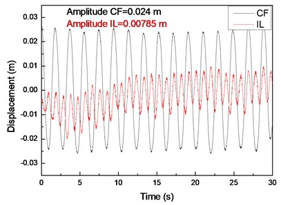
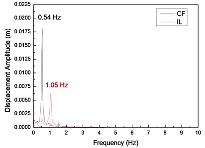
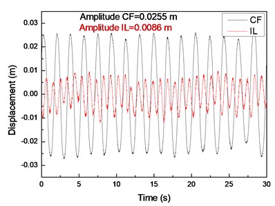
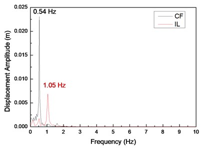
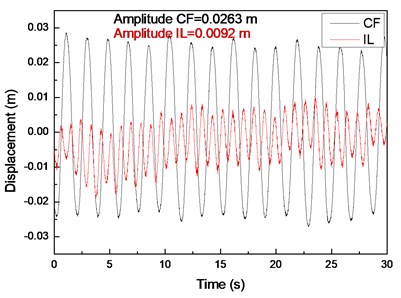
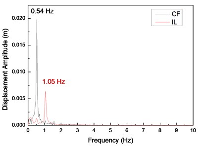
Fig. 4(a), (c), and (e) display the displacement time histories at location 9 with drilling pipe rotation speeds of 0, 60, and 120 r/min and a flow velocity of 0.1 m/s. Fig. 4(b), (d), and (f) display the corresponding fast Fourier transform (FFT) spectra at location 9 with drilling pipe rotation speeds of 0, 60, and 120 r/min and a flow velocity of 0.1 m/s. The variation in the displacement time history in the CF direction is apparent, and the amplitude of the displacement in the CF direction is regular, as shown in Fig. 1(a), (c), and (e). This result indicates that the vibration in the CF direction is stable. However, the variation in the displacement time history in the IL direction is fluctuant. The amplitude of the displacement in the IL direction is not as smooth as that in the CF direction, as shown in Fig. 4(b), (d), and (f). Fig. 4(b), (d), and (f) depict that the dominant vibration frequency in the CF direction is 0.54 Hz, which is approximate to the first order of the natural frequency, as shown in Table 2.
The Strouhal relation is depicted as follows:
where is the vortex-shedding frequency in Hz, is the flow velocity in m and is the Strouhal number ( 0.17) [5].
Fig. 4Displacement responses at location 9 with flow velocity of 0.1 m/s and drilling pipe rotation speeds of 0, 60, and 120 r/min: a), c), and e) displacement time histories in the IL and CF directions; b), d), and f) corresponding fast Fourier transform (FFT) spectra in the IL and CF directions
a)
b)
c)
d)
e)
f)
The vortex-shedding frequency corresponding to the flow velocity of 0.1 m/s and calculated by the Strouhal relation is 0.68 Hz, which is also approximate to the first order of the natural frequency. Previous studies showed that the “lock-in” phenomenon occurs when the vortex-shedding frequency is close to the natural frequency of the riser [1]. When the “lock-in” phenomenon occurs, the riser vibrates at its natural frequency [5]. Accordingly, the “lock-in” phenomenon occurs at the first-order natural frequency of the drilling riser at a flow velocity of 0.1 m/s. Therefore, the dominant vibration frequency in the CF direction is 0.54 Hz. The values of the first-order natural frequency, vortex-shedding frequency, and dominant vibration frequency are slightly different. This deviation is because the natural frequency and vortex-shedding frequency are calculated by the theoretical equation, which may have introduced errors. The riser vibrates significantly in the CF direction under the influence of the “lock-in” phenomenon, and other frequencies are not involved in the vibration, as shown in Fig. 4(b), (d), and (f). Consequently, the vibration in the CF direction is very regular and stable.
The dominant vibration frequency in the IL direction is 1.05 Hz. Evidently, the dominant vibration frequency in the IL direction is almost twice as high as that in the CF direction. This phenomenon has been reported in numerous studies [1-7]. A previous study [5] showed that this phenomenon is caused by the form of the wake mode. With regard to the effect of the wake mode, the force from the vortex shedding acts on the riser in the CF direction once, whereas the force from the vortex shedding acts on the riser in the IL direction twice. Consequently, the dominant frequency in the IL direction is twice as high as that in the CF direction under this “lock-in” phenomenon. Previous studies [1-7] also showed that the vortex-shedding force in the IL direction is much smaller than that in the CF direction. Thus, the vibration amplitude in the IL direction is smaller than and not as smooth as that in the CF direction.
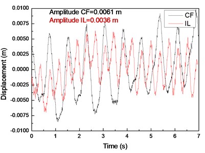
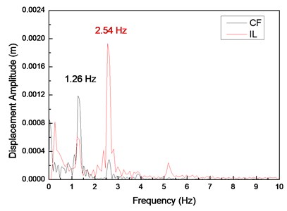
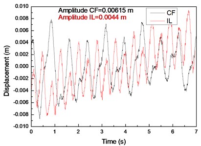
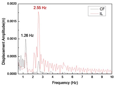
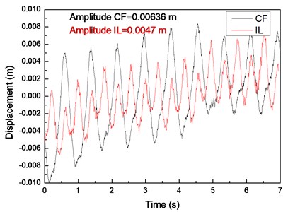
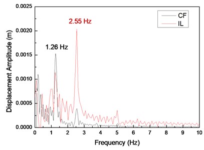
Fig. 5(a), (c), and (e) display the displacement time histories at location 9 with drilling pipe rotation speeds of 0, 60, and 120 r/min and a flow velocity of 0.2 m/s. Fig. 5(b), (d), and (f) display the corresponding FFT spectra at location 9 with drilling pipe rotation speeds of 0, 60, and 120 r/min and a flow velocity of 0.2 m/s. The variations in the displacement time histories in both the CF and IL directions are irregular. The vibration amplitude significantly fluctuates, indicating that the vibrations in both the CF and IL directions are unstable. Fig. 5(b), (d), and (f) show that the dominant vibration frequency in the CF direction is 1.26 Hz, which is approximate to the second order of the natural frequency, as shown in Table 2.
The experimental vortex-shedding frequency calculated by the Strouhal relation at a flow velocity of 0.2 m/s is 1.36 Hz. This value is also approximate to the second order of the natural frequency. Thus, the “lock-in” phenomenon occurs at the second order of the natural frequency, and the riser significantly vibrates at the second order of the natural frequency. On the basis of the given analysis [1-7], the dominant frequency in the IL direction is twice as high as that in the CF direction because of effect of the wake mode under the “lock-in” phenomenon. Consequently, the vibration frequency in the IL direction is 2.54 Hz, which is almost twice as high as that in the CF direction. The vibrations can disturb each other from different directions when the flow velocity is high [10]. As shown in Fig. 5(b), (d), and (f), the vibrations in the CF and IL directions contribute to each other’s vibrations. Accordingly, the vibrations in the CF and IL directions are irregular and unstable.
4.2. Analysis of the effect of drilling pipe rotation speed on the VIV of the drilling riser
Fig. 6 displays the vibration amplitudes at drilling pipe rotation speeds of 0, 60, and 120 r/min and a flow velocity of 0.1 m/s. The vibration amplitude in the CF direction increases from 0.024 m to 0.0263 m when the drilling pipe rotation speed increases from 0 r/min to 120 r/min, as shown in Fig. 6(a). The vibration amplitude in the IL direction increases from 0.00785 m to 0.0092 m when the drilling pipe rotation speed increases from 0 r/min to 120 r/min, as shown in Fig. 6(b).
Fig. 7 displays the vibration amplitudes at drilling pipe rotation speeds of 0, 60, and 120 r/min and a flow velocity of 0.2 m/s. The vibration amplitude in the CF direction increases from 0.0061 m to 0.00636 m when the drilling pipe rotation speed increases from 0 r/min to 120 r/min, as shown in Fig. 7(a). The vibration amplitude in the IL direction increases from 0.0036 m to 0.0047 m when the drilling pipe rotation speed increases from 0 r/min to 120 r/min, as shown in Fig. 7(b).
Fig. 5Displacement responses at location 9 with flow velocity of 0.2 m/s and drilling pipe rotation speeds of 0, 60, and 120 r/min: a), c), and e) displacement time histories in the IL and CF directions; b), d), and f) corresponding FFT spectra in the IL and CF directions
a)
b)
c)
d)
e)
f)
The results depict that the vibration amplitudes in both the CF and IL directions increase with an increase in drilling pipe rotation speed. This phenomenon is caused by that axial force induced by the drilling pipe rotation on the drilling riser, and this axial force increases with an increase in the rotation speed of the drilling pipe [22]. Moreover, the action direction of the axial force induced by the rotation of the drilling pipe is opposite to the direction of the riser tension. The main VIV characteristics of the drilling riser are determined by both bending stiffness and cross-sectional tension, and the vibration amplitude of the riser increases with a decrease in the cross-sectional tension in the same vibration mode [6, 7]. Thus, the vibration amplitude increases with an increase in drilling pipe rotation speed as a result of the decrease in the cross-sectional tension of the drilling riser. However, the influence of the drilling pipe rotation on the vibration amplitude of the drilling riser is insignificant, because the increase in amplitude is insignificant as the drilling pipe rotation speed increases from 0 r/min to 120 r/min, as shown in Fig. 6 and 7. This phenomenon is caused by the axial force induced by the rotation of the drilling pipe on the riser, but the centrifugal effect of the drilling fluid while the drilling pipe is rotating is minimal [22]. Thus, the axial force induced by the rotation of the drilling pipe is minimal. Consequently, the influence of the drilling pipe rotation on the drilling riser vibration amplitude is insignificant when the drilling pipe rotation speed increases from 0 r/min to 120 r/min.
A previous study [22] showed that the vibration frequency could decrease with an increase in the rotation speed of the drilling pipe, because the rotation of the drilling pipe could also affect the cross-sectional tension of the drilling riser. However, Fig. 4(b), (d), and (f) show that the dominant frequencies in both the CF and IL directions are invariant as the drilling pipe rotation speed increases under our experimental conditions. This result can be ascribed to the minimal variations in the displacement amplitudes, as shown in Fig. 6 and 7, and the minimal influence of the drilling pipe rotation on the riser vibration. The sampling frequency is 200 Hz. Therefore, the sampling interval is 0.004 s for the FFT. Consequently, the variation in the vibration frequency cannot be detected during data processing when the variation in the vibration frequency is minimal. The vibration frequency may slightly decrease with an increase in drilling pipe rotation speed as a result of the decrease in the cross-sectional tension of the drilling riser.
Fig. 6Vibration amplitudes at drilling pipe rotation speeds of 0, 60, and 120 r/min and flow velocity of 0.1 m/s
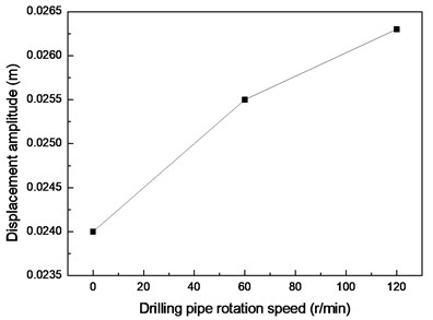
a) CF direction
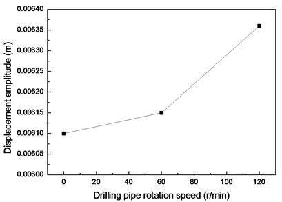
b) IL direction
Fig. 7Vibration amplitudes at drilling pipe rotation speeds of 0, 60, and 120 r/min and flow velocity of 0.2 m/s
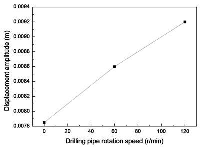
a) CF direction
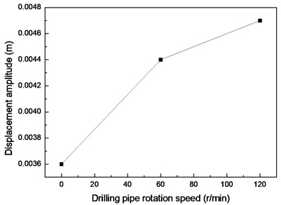
b) IL direction
5. Conclusions
1) Dominant vibration frequency in the IL direction is almost twice as high as that in the CF direction for the effect of the wake mode in the experimental conditions.
2) Vibration amplitude in the IL direction is smaller than that in the CF direction.
3) Vibration amplitudes in both the CF and IL directions increase with an increase in drilling pipe rotation speed under the experimental conditions. However, the influence of the drilling pipe rotation on the drilling riser vibration amplitude is insignificant.
4) Dominant frequencies in both the CF and IL directions are invariant as the drilling pipe rotation speed increases for the influence of the drilling pipe rotation on the drilling riser vibration being insignificant under the experimental conditions.
References
-
Sarpkaya T. Vortex-induced oscillations: a selective review. Journal of Applied Mechanics, Vol. 46, Issue 2, 1979, p. 241-258.
-
Sarpkaya T. A critical review of the intrinsic nature of vortex-induced vibrations. Journal of Fluids and Structures, Vol. 19, Issue 4, 2004, p. 389-447.
-
Bearman P. W. Vortex shedding from oscillating bluff bodies. Annual Review of Fluid Mechanics, Vol. 16, Issue 1, 1984, p. 195-222.
-
Bearman P. W. Circular cylinder wakes and vortex-induced vibrations. Journal of Fluids and Structures, Vol. 27, Issue 5, 2011, p. 648-658.
-
Williamson C. H. K., Govardhan R. Vortex-induced vibrations. Annual Review of Fluid Mechanics, Vol. 36, 2004, p. 413-455.
-
Williamson C. H. K., Govardhan R. A brief review of recent results in vortex-induced vibrations. Journal of Wind Engineering and Industrial Aerodynamics, Vol. 96, Issue 6, 2008, p. 713-735.
-
Gabbai R. D., Benaroya H. An overview of modeling and experiments of vortex-induced vibration of circular cylinders. Journal of Sound and Vibration, Vol. 282, Issue 3, 2005, p. 575-616.
-
Vandiver J. K. Dimensionless parameters important to the prediction of vortex-induced vibration of long, flexible cylinders in ocean currents. Journal of Fluid and Structure, Vol. 7, Issue 5, 1993, p. 423-455.
-
Vandiver J. K., Allen D., Li L. The occurrence of lock-in under highly sheared conditions. Journal of Fluids and Structures, Vol. 10, Issue 5, 1996, p. 555-561.
-
Chaplin J. R., Bearman P. W., Cheng Y., Fontaine E., Graham J. M. R., Herfjord K., Huera Huarte F. J., Isherwood M., Lambrakos K., Larsen C. M., Meneghini J. R., Moe G., Pattenden R. J., Triantafyllou M. S., Willden R. H. J. Blind predictions of laboratory measurements of vortex-induced vibrations of a tension riser. Journal of Fluids and Structures, Vol. 21, Issue 1, 2005, p. 25-40.
-
Trim A. D., Braaten H., Lie H., Tognarelli M. A. Experimental investigation of vortex-induced vibration of long marine risers. Journal of Fluids and Structures, Vol. 21, Issue 3, 2005, p. 335-361.
-
Shiels D., Leonard A., Roshko A. Flow-induced vibration of a circular cylinder at limiting structural parameters. Journal of Fluids and Structures, Vol. 15, Issue 1, 2001, p. 3-21.
-
Pavlovskaia E., Keber M., Postnikov A., Reddington K., Wiercigroch M. Multi-modes approach to modelling of vortex-induced vibration. International Journal of Non-Linear Mechanics, Vol. 80, 2016, p. 40-51.
-
Zhao M. The validity of the independence principle applied to the vortex-induced vibration of an inclined cylinder in steady flow. Applied Ocean Research, Vol. 53, 2015, p. 155-160.
-
Huera-Huarte F. J., Bangash Z. A., González L. M. Towing tank experiments on the vortex-induced vibrations of low mass ratio long flexible cylinders. Journal of Fluids and Structures, Vol. 48, 2014, p. 81-92.
-
Meng D., Chen L. Nonlinear free vibrations and vortex-induced vibrations of fluid-conveying steel catenary riser. Applied Ocean Research, Vol. 34, 2012, p. 52-67.
-
Ren L., Jia Z. G., Ho M. S. C., Yi T. H., Li H. N. Application of fiber Bragg grating based strain sensor in pipeline vortex-induced vibration measurement. Science China Technological Sciences, Vol. 57, Issue 9, 2014, p. 1714-1720.
-
Thorsen M. J., Sævik S., Larsen C. M. A simplified method for time domain simulation of cross-flow vortex-induced vibrations. Journal of Fluids and Structures, Vol. 49, 2014, p. 135-148.
-
Franzini G. R., Gonçalves R. T., Pesce C. P., Fujarra A. L. C., Mazzilli. C. E. N., Meneghini J. R., Mendes P. Vortex-induced vibration experiments with a long semi-immersed flexible cylinder under tension modulation: Fourier transform and Hilbert-Huang spectral analyses. Journal of the Brazilian Society of Mechanical Sciences and Engineering, Vol. 37, Issue 2, 2015, p. 589-599.
-
Yin D., Larsen C. M. On determination of VIV coefficients under shear flow condition. 29th International Conference on Ocean, Offshore and Arctic Engineering. American Society of Mechanical Engineers, 2010, p. 547-556.
-
Liu Q., Mao L., Zhou S. Experimental study of the effect of drilling pipe on vortex-induced vibration of drilling risers. Journal of Vibroengineering, Vol. 16, Issue 4, 2014, p. 1842-1853.
-
Major I. E., Big-Alabo A., Odi-Owei S. Effect of drill string rotation on the dynamic response of drilling risers. International Journal of Applied Mechanics and Engineering, Vol. 20, Issue 3, 2015, p. 503-516.
-
Lie H., Kaasen K. E. Modal analysis of measurements from a large-scale VIV model test of a riser in linearly sheared flow. Journal of Fluids and Structures, Vol. 20, Issue 3, 2006, p. 557-575.
About this article
The authors gratefully acknowledge the financial support of the National Natural Science Foundation of China (No. 51604235).
