Abstract
To analyze the deflector-jet servo valve’s internal flow characteristics, a theoretical model of the complicated flow distribution in the deflector plate is established based on the offset jet attachment theory. When the deflector plate offsets, jet attachment parameters are attained to figure out the jet’s bending and colliding process. On this basis, an analytical method of acquiring the pilot valve’s pressure gain is derived. According to an actual pilot stage’s structure, pressure gain calculations are carried out. Meanwhile, the pilot valve’s mesh model is established for numerical simulation in order to examine the accuracy of the theoretical model. Calculation and numerical simulation show that the final oil jet is not sensitive to the deflector plate’s movement, which directly reveals the pressure stabilizing effect of the V-shaped structure on the deflector plate. Moreover, the experiment on the pressure gain is accomplished and experiment results verify the accuracy of the analytical calculation.
1. Introduction
The deflector-jet servo valve (DJSV) is derived from the jet-pipe servo valve, composed of a torque motor, a deflector-jet pilot stage amplifier and a valve. With the advantages of high resistance to contamination, good dynamic performance and high reliability, DJSV is key part in servo control system and vibration engineering, and widely applied in aerospace and industrial fields recently. Compared with spool valves and flapper-nozzle valves, research on jet valves is insufficient. As to jet-pipe valves, Pham [1, 2] derived theoretical formulas of the pilot stage’s flow distribution, and Shang [3] and Li [4] finished analysis based on CFD simulation. Then Yin [5] and Li [6] respectively accomplished complete theoretical models and numerical simulations, in which the jet-pipe valve’s various characteristics were discussed. In addition, Somashekhar [7] constructed a jet pipe’s fluid structure interaction model and Wang [8] simulated the water jet valve, while Chu [9] investigated wear abrasion about jet valves. As an improvement of the jet-pipe valve, the deflector-jet valve became another research topic gradually. Wang [10] built a throttling model of a deflector-jet pilot stage, and got the simplified linear flow equation. And Yang [11] finished numerical simulations and visualized experiments on different pilot stage’s flow distributions and found that it was easier to flow along the flat cutting structure in two receiver entrances of the jet pan. Furthermore, Yin [12, 13] proposed a method to restrain the cavitation in pilot stage after summarizing the effect of valve pressure, oil pressure and the angle of receiver tube. Based on the turbulent impact jet theory, Jiang [14] came up with a new way to analyze the deflector-jet pilot stage and optimized its structure parameters. Dhinesh K. S. [15] proposed a DJSV based on bi-piezoelectric crystals and improved its performance. Moreover, Zhu [16] designed a new DJSV using giant magnetostrictive material that had a high response speed.
However, most pilot stage models were obtained according to the jet-pipe valve, not the real DJSV. Additionally, it is not accurate to describe the complicated change of turbulent jet flow in such a small structure without considering the jet flow’s bending and colliding. Consequently, those theoretical formulas and relevant conclusions of DJSV are not in agreement with numerical test and experiment results.
In order to describe a DJSV’s flow distribution more accurately, the model which is built in this paper uses the rectangular jet structure different from Zhu’s. The researches can mostly be divided into two parts: firstly, a novel theoretical model of pilot stage’s flow is built based on offset jet attachment theory. The oil’s flow process from jet-pan to oil’s outlet is divided into four stages to explore reasonable mathematical descriptions; Secondly, using the formulas built from the former part and flow distribution characteristics in pilot stage, the pilot stage’s pressure gain formula is achieved. Then, the theoretical calculation and the numerical simulation are carried out to acquire the jet attachment parameters and the pilot stage’s pressure gain by MATLAB and Fluent respectively. In the last part, a pressure gain experiment is designed to verify the theoretical model’s accuracy.
2. Operating principle of DJSV
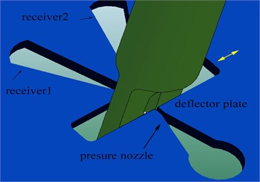
The structure of DJSV is shown in Fig. 1. As the core of the servo valve, the deflector-jet pilot valve consists of a deflector plate and a jet pan. The relationship between the two parts is shown in Fig. 2.
Fig. 1Structure of a deflector-jet servo valve: 1 – torque motor, 2 – deflector plate, 3 – jet pan, 4 – feedback rod, 5 – spool, 6 – nozzle with pressure, 7 – receiver I, 8 – receiver II, 9 – control chamber
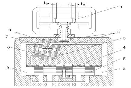
The jet pan is a wafer with some holes as shown in Fig. 2, including a pressure nozzle, oil outlets on both sides and two receivers which are connected to the control chambers of the spool valve. The deflector plate is a V-shaped guiding groove structure, inserting the space between the jet pan nozzle and receivers. When the deflector plate moves in direction, the pressures in two control chambers will change to drive the spool. Then the deflector-jet components, the spool, the feedback rod and torque motor form a closed loop system.
Fig. 2Structure of deflector-jet components
3. Model and characteristics of deflector-jet pilot stage
3.1. Main cross sections of flow distribution
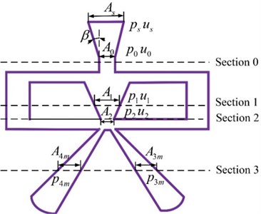
In this work, the oil is considered as incompressible viscous fluid. Four cross sections are selected in the flow distribution, as shown in Fig. 3. The velocity and pressure of the flow for each section need to be analyzed.
In Fig. 3, is the area of the jet pan entrance, is the supply oil pressure of servo valve,is the original velocity when oil flows into jet pan and is the gradual contractile angle of the jet pan entrance. Section 0, 1 and 2 respectively represent the virtual jet origin, the jet collision location on the lateral wall of the V-shaped guiding groove and the nozzle on the deflector plate. Correspondingly, the sectional areas are , , . Besides, the pressure and velocity of each cross section are defined as and . Section 3 is determined concerning the location where the flow velocity is 0 when the deflector plate is at the neutral position. The two sectional areas are respectively and , and the restoring pressures in them are defined as , .
Fig. 3Definition of the pilot stage pressure section
3.2. Initial part of pilot stage’s flow
As shown in Fig. 3, the oil comes into the jet pan and flows into Section 0. The equation derived from the ideal Bernoulli equation can be written as:
where is the oil density, is the gravity, is the potential energy in the jet pan entrance, is the potential energy in cross Section 0, and is the loss of tube friction resistance.
When the servo valve works normally, the oil original velocity is very slow, so . Because the pilot stage is in horizontal direction, the influence of potential energy can be ignored and can be assumed. The loss of tube friction is and is the friction factor of a square gradual contractile tube in the jet pan entrance. So, Eq. (1) can be expressed as Eq. (2):
Suppose that 16 MPa, from Eq. (2) the Reynolds number’s calculation result of the nozzle in the jet pan is 3066.6, which is much bigger than the critical Reynolds number [17]. So, the jet flow in pilot stage is turbulent.
3.3. Attachment property description of pilot stage’s flow
Observing the structure from Section 0 to Section 1, the jet flow happens in the thin jet pan that is covered by top and bottom sealing cover, so the jet can be regard as 2-D jet [18]. When the oil comes into the limited space of the V-shaped guiding groove, the interference of the lateral wall and jet flow happens with an entrainment effect on ambient fluid. Eventually, the jet flow attaches on the wall which is called offset jet attachment effect or coanda effect. Based on the below assumed conditions [19], the jet attachment effect of the pilot stage’s flow can be described.
(1) The flow velocity is identical when the oil comes out from the jet pan. And the flow trajectory is approximately regarded as part of an arc between the jet central line of the nozzle and the collision central point on the lateral wall of the deflector plate;
(2) Ignoring the friction loss of the sealing covers and the energy loss of collision with lateral wall, the fluid momentum is invariant in the process of fluid’s jet before collision;
(3) The static pressure in the jet flow is equal everywhere.
The schematic diagram of the wall attachment jet in a pilot stage’s flow is shown in Fig. 4.
Fig. 4Geometry model of the wall attached jet in pilot stage
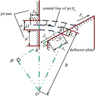
In Fig. 4, is the width of the jet pan nozzle and is the position difference which is the distance between the nozzle and the intersection point B of the lateral wall’s extended line and the jet pan’s boundary. Assuming that the virtual jet original point is , the distance between the point and the nozzle is , and the inclination angle of the lateral wall is . From condition Eq. (1), the curvature radius of the jet middle line can be supposed to and the circle center is located at . The collision angle between jet and the lateral wall is and the collision point between the jet bottom line and the lateral wall is in point C. The arc length of the jet middle line is and the vertical distance between the jet central line and the jet boundary is . According to condition Eq. (2), it is assumed that the original jet momentum is . After collision with the lateral wall, the oil on the right of point C continues flowing to the deflector plate along the lateral wall and the momentum is . In the meantime, the oil on the left of point C flows back to the low pressure vortex zone and its momentum is .
3.3.1. Location of virtual original jet point
Considering that the jet pan nozzle has a limited width, the main body of pilot stage jet flow can be described by the Goerler 2-D free turbulent jet model. The distribution of flow velocity is expressed as:
where is the velocity of the jet axis, is the transverse coordinate of the jet, is the curvilinear coordinate of the jet central line that originates from the nozzle, is the jet diffusion factor, and is the oil’s momentum in total at the jet pan nozzle. Assuming that the flow velocity in the virtual jet origin O is , the rate of the flow from the nozzle is:
Combining Eqs. (3-5) and , the distance between the virtual jet origin and the nozzle is shown in Eq. (6):
3.3.2. Momentum of collision point
Before the jet flow touches the lateral wall, the momentum will keep invariant without external force. Then according to the impulse theorem, the momentum conservation of the impact jet along the lateral wall can be expressed as:
After the collision, the downstream oil’s momentum and the reflux oil’s momentum can be given by:
Substituting Eqs. (3-4) into Eqs. (8-9), the oil’s momentums along the lateral wall of the deflector plate at the collision point C can be expressed as:
According to Eq. (7) and Eqs. (10-11), the relationship between and can be described as:
3.3.3. Jet collision angle
Because Point C is the boundary point of the flow’s direction, the reflux rate of flow can be expressed as:
On the other hand, the entrainment rate of flow at the arbitrary point of the jet flow line is:
where is the arc length from the nozzle to the arbitrary point on the jet flow line. Without considering other exits in the vortex zone, the entrainment rate of flow at the length of and the reflux rate of flow are equal, that is:
From Eqs. (13-15) and Eq. (6), we can obtain:
According to Fig. 4, and can be expressed as:
Thus, from Eq. (12), Eq. (16) and Eqs. (17-18), the jet collision angle can be acquired by:
Then the arc length of jet central line is:
And the vertical distance between jet middle line and jet inner boundary is:
Obviously, jet attachment position difference in Eq. (19) is relevant to the displacement of the deflector plate and the distance between the deflector plate and the jet pan nozzle, which is shown in Fig. 5.
Fig. 5Schematic diagram of deflector offsets
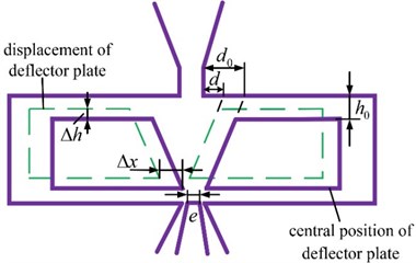
In Fig. 5, is the original distance between the deflector plate and the jet pan nozzle, and the middle position difference is .When the servo valve works. is the displacement of the deflector plate and is the vertical distance variety between the deflector plate and the jet pan caused by servo valve assembly, so the position difference can be given by:
According to Eq. (19), the jet collision angle is calculated by:
where is the middle position difference’s dimensionless value, is the deflector plate displacement’s, and is the vertical distance variety’s. Consequently, the pilot stage jet collision angle is affected by the width of the jet pan nozzle, the middle position difference, the displacement of the deflector plate, the inclination angle of lateral walls and the vertical distance between the deflector plate and the jet pan nozzle. And the original jet momentum is irrelevant to the collision angle.
3.3.4. Jet collision distance
According to the geometric relation in Fig. 4, we can obtain:
Combining Eq. (18), Eq. (21), Eq. (22) and Eqs. (24-25), the jet collision distance can be obtained by:
Thus, the collision distance is affected by many parameters, such as the collision angle, the lateral wall’s inclination angle, the width of the jet pan nozzle , the displacement of the deflector plate and the vertical installing location variety.
3.4. Pilot stage pressure gain
After collision with the deflector plate’s lateral wall, part of oil continues to flow along the lateral wall from cross Section 1 to 2 and reaches the deflector plate’s nozzle, which is shown in Fig. 3. Supposing that the principal part of the oil jet has the same pressure, the pressure at Section 1 can be express as below:
According to Eq. (3), the velocity at Section 1 can be given by:
Considering the square gradual contractile loss of the V-shaped guiding groove [20], ignoring the factor of potential energy and applying Bernoulli equation, we can learn the description of the pressure variety that is expressed as:
where is the friction factor of the lateral wall. can be calculated from Eqs. (22-26). And can be obtained from the fluid’s continuity condition, then is achieved from Eqs. (3-4), Eq. (6), Eq. (20), Eq. (27) and Eq. (29).
Through the flow continuous theory, is obtained from Eq. (28) and Eq. (30):
By analyzing the process from Section 2 to 3 in Fig. 3, the inner flow situation in the pilot valve is shown in Fig. 6.
Fig. 6Schematic diagram of the flow distribution in pilot stage
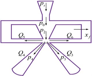
In Fig. 6 , , and are respectively the rates of flow in the receivers of the jet pan and in the gaps between the deflector plate and the jet pan. and are the entrance pressures of the two receivers, while is the displacement of the deflector plate. Assuming that the valve is symmetric and the oil supply’s pressure, temperature and density are constant, the rates of flow in the receivers and in the gaps can be shown as follows:
where , , , and are these flow rates’ corresponding throttling areas and is the throttling coefficient. Based on the actual pilot valve structure, the relative position between the nozzle of the deflector plate and the jet pan receivers is shown as Fig. 7.
Fig. 7Relative position between deflector plate nozzle and receivers
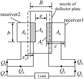
In Fig. 7, is the length of receiver entrance, is the width of receiver entrance, is the distance between the two receivers, is the width of the deflector plate nozzle and is the load flow rate. According to Fig. 7, when the deflector plate turns to the right, the calculation of each throttling area can be shown as:
And the load flow rate can be calculated by:
When the deflector plate is at neutral position and the entrance pressures of the two receivers are equal, then according to Eqs. (31-39), we can obtain:
where , indicating the relative position between the deflector plate nozzle and the jet pan receivers. Because each receiver is closed, the flow velocities in the receivers drop significantly while the pressures increase to the recovery pressure, which can be given by:
According to Bernoulli equation, where and are the square divergent friction factors of the lateral walls of the receivers. The load pressure is the difference of the two receivers’ recovery pressures, i.e.:
Obviously, the load flow rate is the function of the deflector plate displacement and the load pressure . Then the load rate can be approximated with a Maclaurin’s expansion of the first order, which is written as:
Since can be calculated by Eqs. (31-43), according to Eq. (44), we can get:
Thus, according to Eq. (45), the pressure gain can be calculated by:
From Eq. (46), we can learn that the pressure gain is affected by the nozzle pressure of deflector plate, the receivers’ width, the receivers’ distance, and the size of the deflector plate nozzle, but it is irrelevant to the thickness of the jet pan. When the load flow rate is zero, the load pressure is shown as below:
Considering Eq. (47), the larger the pressure gain, the better the valve’s pressure sensitivity.
4. Simulation analysis of deflector jet pilot valve
4.1. Discussion on theoretical model
Based on the derivation in the previous chapter, calculation and analysis for attachment properties can be made according to the structure parameters shown in Table 1.
Table 1Main parameters of a deflector jet pilot valve
Parameters’ name | Data |
Oil density | 870 kg/m3 |
Inclination angle of the deflector plate’s lateral wall | 15° |
position difference in middle | 0.25 mm |
Width of the jet pan nozzle | 0.15 mm |
Original distance between the deflector and the jet pan | 0.2 mm |
Oil Supply’s pressure | 21 MPa |
Distance between the two jet pan receivers e | 0.1 mm |
Based on Eq. (6), the distance between the jet origin and the jet pan nozzle is calculated as 0.33 mm. Considering the case that deflector plate moves to the left and the offset range is 0-0.04 mm, the collision angle and the collision distance affected by deflector plate offset are indicated in Figs. 8-9.
Fig. 8Jet’s impact angle
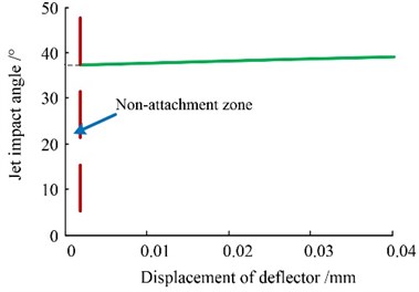
Fig. 9Jet’s collision distance
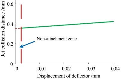
Fig. 10Deflector plate nozzle’s pressure
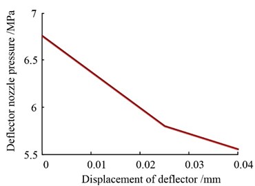
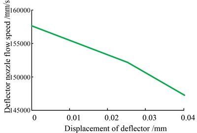
Fig. 11Deflector plate nozzle’s flow speed
Hence the deflector plate’s offset has slight influence on the collision angle and distance, because the offset is so small and the guiding groove’s V-shaped structure restrains the free jet’s length and diverging effect. Meanwhile, there is a zone without attachment around the deflector plate’s neutral position, since the deflector plate and the jet pan nozzle have symmetric structures. This non-attachment zone can be observed from the numerical simulation, though it is very small and difficult to be described analytically.
The deflector plate’s nozzle pressure and flow velocity are indicated in Figs. 10-11. It is shown that when the deflector plate is in the center, the nozzle pressure is 7.74 MPa. As the deflector plate offsets in the left direction, the deflector plate nozzle’s pressure decreases by the speed of 0.067 MPa/0.01 mm and the deflector plate nozzle’s flow velocity also declines.
In accordance with Table 1 and Eq. (47), we can calculate the average pressure gain under 0.04 mm displacement, with the result that 122 MPa/mm. However, with the deflector plate’s movement, the pressure gain decreases gradually, as shown in Fig. 12. Additionally, this theory shows that there is an approximately linear relation between the deflector plate’s displacement and the pressure gain.
Fig. 12Pressure gain of the pilot valve
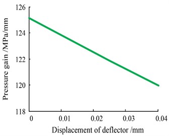
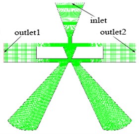
Fig. 13Mesh of the jet deflector servo valve pilot stage
4.2. Numerical simulation of pilot valve
Considering that the deflector plate’s offsets are respectively 0 mm, 0.02 mm and 0.04 mm, the 2-D mesh models of pilot valve’s flow distribution are built. For example, mesh dividing of 0 mm offset is displayed in Fig. 13.
With the supply pressure of 21 MPa, the oil density of 870 kg/m3 and the kinematic viscosity of 0.0087 kg/ms, the pressure and velocity distribution contours can be listed in Fig. 14, when the deflector plate’s offsets are 0 mm, 0.02 mm and 0.04 mm.
After collision, small part of oil flows back to the return-oil outlet on both sides by the gaps between the deflector and the jet pan, and other oil continues to flow along the lateral wall. The flow pressure increases because of the constriction of the guiding groove’s lateral wall and then the jet comes out from the deflector plate nozzle again. In fact, the lateral wall can significantly improve the stability of turbulent jets. The numerical simulation result is in agreement with the description of the offset jet attachment model in Section 2.
From the numerical simulation result, the deflector plate’s nozzle pressure, nozzle velocity, the jet’s collision angle and the collision distance are listed in Table 2.
Table 2Jet attachment characteristics from numerical simulation
Offset (mm) | (MPa) | (mm/s) | (°) | (mm) |
0.00 | 7.84 | 157000 | - | - |
0.02 | 7.62 | 152000 | 40 | 0.36 |
0.04 | 7.33 | 145000 | 42 | 0.40 |
From Table 2, with the offset’s increasing, the jet collision angle has no significant growth, while the collision point is moving down to the deflector plate nozzle. The deflector nozzle’s pressure and flow velocity decrease slightly. Comparing the theoretical calculation with the numerical simulation, the difference is shown in Table 3.
In addition, the pressure in the two receivers can be attained by Fig. 14, listed in Table 4.
So, the DJSV’s average pressure gain is 126 MPa/mm according to above data, which is consistent with the model-based calculation.
Table 3Relative errors between calculation and numerical simulation
Offset (mm) | ||||
0.00 | 1.15 % | 4.25 % | – | – |
0.02 | 0.66 % | 2.56 % | 5.50 % | 5.56 % |
0.04 | 1.64 % | 2.68 % | 6.90 % | 6.98 % |
Table 4Pilot stage’s pressure gain and the recovery pressures in two receivers
Offset (mm) | (MPa) | (MPa) | (MPa/mm) |
0.00 | 7.05 | 7.05 | – |
0.02 | 8.36 | 5.81 | 127.5 |
0.04 | 9.62 | 4.63 | 124.7 |
Fig. 14Pressure and velocity contours of the flow distribution with different deflector offsets

a) Pressure contour (offset from 0 mm to 0.04 mm in order)

b) Velocity contour (offset from 0 mm to 0.04 mm in order)
5. Experiment and analysis of pressure gain
5.1. Experiment design of pressure gain
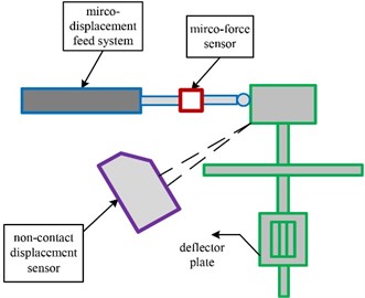
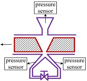
The equipment is designed to achieve micro-displacement’s precise control and measurement. Aiming at a special servo valve with an extension outside the housing, a high-precision electric push rod is set to drive the torque motor and a laser sensor is used for detecting the movement, which is showed in Fig. 15 and Fig. 16. Thus, the deflector plate’s displacement can be calculated according to the structural dimensions while the restoring pressure , can be detected directly. Consequently, the real pressure gain will be obtained by Eq. (47).
5.2. Experiment results analysis
Applying the supply pressure of 21 MPa and driving the deflector plate from 0 mm to 0.04 mm, the restoring pressures in the two receivers are shown in Fig. 17 and Table 5.
The result shows that when the deflector is in the center, the pressure testing value in each receiver is 6.7 MPa which has an error of 6.16 % with regard to the calculating result. Based on the experiment data and Eq. (47), the pressure gain average value is 118 MPa/mm, which has an error of 3.28 % with regard to the calculating result 122 MPa/mm. So, it has been showed that the theoretical calculations and the experiment results are essentially coincident, which verifies correctness and rationality of the proposed theoretical model. In fact, the testing pressure gain will decline with the deflector plate offset’s increasing, which is also consistent with the calculation and simulation, as shown in Fig. 18.
Fig. 15Driving and detecting method of deflector plate
a)
b)
Fig. 16Test device for pressure gain
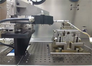
Fig. 17Recovery pressures at the jet-pan receivers
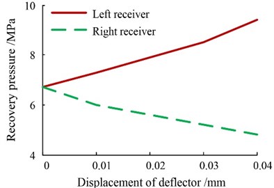
Fig. 18Pressure gain contrast
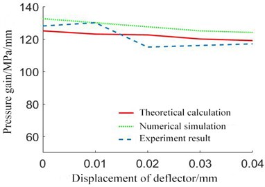
Table 5Experiment data of recovery pressure
Receiver | Offset (mm) | ||||
0.00 | 0.01 | 0.02 | 0.03 | 0.04 | |
Left (MPa) | 6.7 | 7.4 | 8.0 | 8.5 | 9.4 |
Right (MPa) | 6.7 | 6.0 | 5.6 | 5.1 | 4.7 |
6. Conclusions
The proposed pilot valve’s model based on wall attachment theory can describe the jet flow distribution in the deflector plate’s limited space. This theoretical model can be utilized for calculations of wall attachment parameters. Based on Bernoulli equation, the two fluid jet procedures can be bridged and a complete steady model of the deflector jet structure is established. Thus, the pressure gain can be computed.
Theoretical calculation and numerical simulation show that the deflector plate nozzle’s pressure and flow rate does not decline apparently as the deflector plate offsets, because of the deflector plate’s V-shaped structure. Thus, with the advantage of a low moment of inertia, the deflector plate and the jet pan can take place of the traditional jet-pipe at the cost of returned oil’s energy loss after collision.
Experiments on the pressure gain verifies the validity of the theoretical calculation, so the 2-D method of modeling the flow distribution for the deflector valve can be seen as a reasonable choice. On this basis, the flow distribution’s time varying and dynamics characteristics appear considerable.
References
-
Pham X. H. S., Chen T. F. Mathematical model of steady state operation in jet pipe electro-hydraulic servo valve. Journal of Donghua University, Vol. 30, Issue 4, 2013, p. 269-275.
-
Pham X. H. S., Yin Y. B. Research on fluid characteristics of jet pipe electro-hydraulic servo-valve based on structural parameters. International Conference on Intelligent Human-Machine Systems and Cybernetics, Hang Zhou, China, 2012, p. 310-313.
-
Shang Y. X., Zhang X. S., Chang-Wei H. U., et al. Optimal design for amplifier of jet deflector servo valve. Machine Tool and Hydraulics, 2015.
-
Ru-Ping L. I., Nie S. L., Meng-Lin Y. L, et al. Simulation investigation on fluid characteristics of jet pipe water hydraulic servo valve based on CFD. Journal of Shanghai University, Vol. 15, Issue 3, 2011, p. 201-206.
-
Yin Y. B., Wang Y. Pressure characterization of the pre-stage of jet pipe servo valve. Journal of Aerospace Power, Vol. 30, Issue 12, 2015, p. 3058-3064.
-
Li Y. Mathematical modelling and characteristics of the pilot valve applied to a jet-pipe/deflector-jet servovalve. Sensors and Actuators a Physical, Vol. 245, 2016, p. 150-159.
-
Somashekhar S. H., Singaperumal M., Kumar R. K. Modelling the steady-state analysis of a jet pipe electrohydraulic servo valve. Proceedings of the Institution of Mechanical Engineers Part I Journal of Systems and Control Engineering, Vol. 220, Issue 2, 2006, p. 109-129.
-
Wang X. H., Li Z. J., Sun S. W., et al. Investigation on the prestage of a water hydraulic jet pipe servo valve based on CFD. Applied Mechanics and Materials, Vol. 197, 2012, p. 144-148.
-
Chu Y., Yuan Z., Ying Z., et al. Erosion wear characteristic of jet pipe servo valve. Hangkong Xuebao/ACTA Aeronautica et Astronautica Sinica, Vol. 36, Issue 5, 2016, p. 1548-1555.
-
Wang C., Ding F., Qipeng L. I., et al. Dynamic characteristics of electro-hydraulic position system controlled by jet-pan servovalve. Journal of Chongqing University, 2003.
-
Yang Y. H. Analysis and Experimental Research of Prestage Jet Flow Field in Hydraulic Servo Valve. Harbin Institute of Technology, Harbin, 2006.
-
Yin Y. B., Zhang P., Zhang Y. Analysis of the pressure characteristics of deflector jet servo valve. Fluid Power Transmission and Control, Vol. 65, Issue 4, 2014, p. 10-15.
-
Yin Y. B., Zhang P., Cen B. Pre-stage flow field analysis on deflector jet servo valves. Chinese Journal of Construction Machinery, 2015.
-
Jiang L. Q. Design and Research on a New Type of Deflection Plate Jet Servo Valve. Southeast University, Nanjing, 2013.
-
Dhinesh K. S., Andrew R. P., Christopher R. B., Paul G. Modelling and experimental validation of a novel piezohydraulic servovalve. Proceedings of the ASME 2011 Dynamic Systems and Control Conference, Arlington, VA, USA, 2011, p.345-350.
-
Zhu Y., Li Y. Development of a deflector-jet electrohydraulic servovalve using a giant magnetostrictive material. Smart Materials and Structures, Vol. 23, Issue 11, 2014, p. 115001-115019.
-
Dong Z. Y. Jet Mechanics. Science Press, Beijing, 2005, p. 15-17.
-
Tan F. J. The Retrofit Design of Fluid Efflux Hammer and Its MATLAB Simulation Computation. Jilin University, Changchun, 2005.
-
Gao N., Dan E. Experimental investigation of planar offset attaching jets with small offset distances. Experiments in Fluids, Vol. 42, Issue 6, 2007, p. 941-956.
-
Pramanik S., Das M. K. Numerical study of turbulent wall jet over multiple-inclined flat surface. Computers and Fluids, Vol. 95, Issue 95, 2014, p. 132-158.
Cited by
About this article
Supported by Foundation of Key Laboratory of Vehicle Advanced Manufacturing, Measuring and Control Technology (Beijing Jiaotong University), Ministry of Education, China.
Yan’s give professional advices and supervise the study direction; Kang solves a lot of CFD problems; Dong helps with this paper works; professor Li direct the servo-valve’s experiment.
