Abstract
For example, a typical brick building is considered in the process of modeling and calculation of loaded deformed condition of the space system building-base-ground. The numerical implementation of the nonlinear problem in view of the structural destruction of materials by finite element method is in accordance with the developed algorithm. Crack propagation is presented in pattern and contour plots of stress and displacement, resulting from the calculation.
1. Introduction
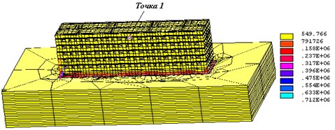
The process of modeling and calculation of loaded strained state (LSS) building-base-ground spatial system (BBG) consider a typical five-story brick building. The building consists of four sections with a total length of 60m, 12m wide, 16 m high. The material of exterior and interior walls is brick of grade 100 and grade 50. The thickness of the exterior walls of 0.65 m, of interior – 0.45 m for illustration in Fig. 1 and 2 shows the results of calculating displacements (pellet) and a stress intensity BBG system.
Fig. 1Movement uz in BBG system (m)
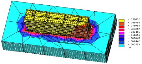
Fig. 2Stress intensity σi in BBG system (kg/m2)
2. Computational experiments
After an analysis of the results of numerical experiments using the method of sub-models [1], it was found that in order to achieve practical convergence, a rather coarse grid can be used for both movements, and stresses on the full model, specifying the decision only in the zone of sub-models [2]. Conducted testing program calculations using the Petch-test showed that the values of displacements and stresses obtained on a regular and chaotic designed grids differ slightly, i.e. it is possible to trust the software system used during these calculations.
Fig. 3Diagram of load-bearing wall of building façade
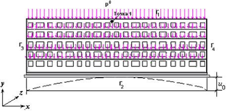
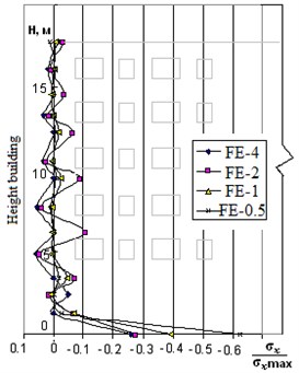
Fig. 4Graph of relatively normal stress on left side wall building height for different sizes finite element mesh
It is much easier to simulate load-bearing wall of the building than to model the whole building, so if you do not need to take into account the torsion of the object, and are interested only in a bend in the plane of the building, the designers usually consider only the bearing wall or wall fragments [1, 3]. A geometrical model of the bearing wall of 5-storey brick building in conjunction with the foundation is shown in Fig. 3. It takes into account all the window openings. Wall modeled volume is eight-node end of Solid elements [4]. Mesh nodes elements are arranged randomly, with concentration in the areas of its expected gradient of the unknown quantities.
Fig. 4 shows the results of stress analysis σh as a ratio to the maximum value max σh on the left side wall of the building height to four meshes of finite elements: with maximum dimensions of finite elements 4 m, 2 m, 1 m and 0.5 m (designation FE-4, FE-2, FE-1 and FE-05), which show that the grid FE-1 and less natural boundary conditions are practically fulfilled, indicating the accuracy of the obtained numerical solutions [1, 5].
3. Crack propagation
Numerical realization of a nonlinear problem in view of the structural destruction of materials by finite element method [6] was carried out in accordance with the developed algorithm. Painting crack propagation and contour plots stress and displacement resulting from the calculation are shown in Fig. 5.
Fig. 5Picture of crack propagation

Nonlinear analysis taking into account the structural damage masonry material showed a significant difference of stress distribution in nature σh bearing wall of the building and their numerical values (in 1.3-2 times) from the linear analysis results and no significant differences (~2.5 %) in displacements kinematic exposure.
The inclusion of openings in the building calculation model, when calculating the spatial systems using the finite element method (FEM) and modern software, does not cause much difficulty, but it leads to a constructional complication geometric models and, consequently, high costs and time necessary to monitor the presence of “bad” finite elements [7]. So, naturally it is desirable to explore the possibility not to include windows and doors in the design scheme and consider their influence decline in the elastic properties of the material [8, 9].
Fig. 6Move uz in building with windows and doorways
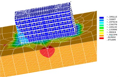
Fig. 7uz movements in a building with no window openings with given modulus of elasticity
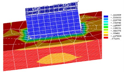
To analyze the spatial BBG, a system, in which buildings were considered in two versions: with window openings (see Figure 6), and without openings (Figure 7), was modeled. These figures show the results of the settlement calculation for two variants of buildings. Uniform and thus investigated different stiffness characteristics of the ground were primarily accepted.
As shown by numerical experiments for a hard ground account opening has less effect on the building rainfall, but the difference precipitate buildings with no more than 5 %.
These results allow the calculation of spatial settlement structures are not included in the calculation window and door openings, and if the calculation is carried out without the inclusion of the soil mass - their impact given modulus of elasticity should be taken into account.
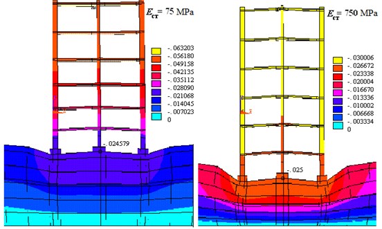
Fig. 8 shows the system BBG fragments isolated from the bulk problems. They show that an increase in the stiffness of the walls, the most loaded section down from the top floors down to the foundation. The maximum vertical displacement of the walls with a decrease in stiffness is 10 times of about 2 times the value of the displacement tighter the building, but on the foundation base level, these movements (buildings rainfall) are aligned. Thus, this calculation also confirms that for the calculation of settlement superstructure cannot be included in the calculation model.
Fig. 8Distribution uz movements in construction for different values of modulus of elasticity of wall material
Traditionally, in practice, the calculation is made on the tape base scheme of plane deformation of the transverse stripes on the elastic foundation [10]. To assess the possibility of using such a model, boundary value problems in linear formulation were solved where the simulated cross section of strip foundation was in the inhomogeneous elastic foundation, fixed at the lower end [14, 15]. The load is the weight of building. The results obtained with this task, compared with the results of solution volume targets and get close enough outside the influence of the edge effect [16].
When designing the building structures, completely rigid stand on the base is usually considered, and derived from the reaction of this calculation, used to calculate the foundation and the base in the form of load, which is applied on the elastic or elasto-plastic medium [10-12]. In order to determine how it is reasonable, weather this approach makes possible to obtain reliable results – nor not, two design schemes and accordingly resolved two-dimensional boundary value problems: the “base-soil” system under the influence of the weight load of building and BBG system, were considered [13].
Fig. 9Settlement in the solution of building linear problem
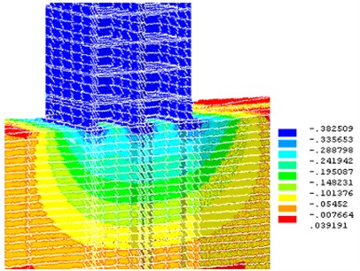
Fig. 10Settlement of building, taking into account nonlinear behavior of subgrade
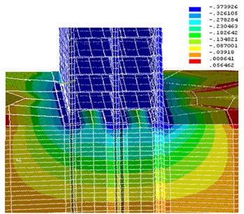
The calculation results of movements (settlement) obtained in the linear and nonlinear problems, are shown in Fig. 9 and 10, respectively. Considering the complexity of subgrade structure and mechanical behavior, variability of the properties of real soils, in each particular case it is required to assess the non-project impact on the construction of analysis, which includes a thorough study of the physical and mechanical properties of concrete grounds [17].
As a result of numerical analysis of the effect of soil mass, the size of LSS on the building, the following ratios of the building size (Lb) and the base (L), at which it is possible to use different boundary conditions: when L > 0.12 Lb and provided that the lateral surface of the soil can be fixed only to define movement (draft); for the analysis of the stress state of the building at L < 0.25 Lb is not recommended to use the model without taking into account the lateral grouting array; when L ≥ 0.3 Lb model BBG array of soil cannot be fixed on the side surfaces.
4. Structure reinforcement
Consider a real hands-on experience in the application of numerical simulation methods and in the design of real construction projects. This should help to assess the impact of the designed building on the neighboring buildings, to ensure their safety, and to prevent from damage.
In solving this problem, a computer technology has been developed, which included three tasks: a numerical analysis of a foundation slab project for a new building; an impact study of a new building on the existing one; a numerical reinforcement study of the foundations of adjacent buildings [20].
Fig. 11Diagram of foundation plate with elastic foundation
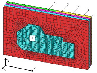
In solving the first problem, the configuration of reinforced concrete foundation slab was specified in terms of new construction (Fig. 11) and defined load circuit acting on the plate, including the building weight, a layer weight of the ground height of 2 m, which lies on the field of fundamental plates located outside the contour of the external walls of the building and foundation of its own weight.
We considered four different base layer thickness-averaged properties obtained as a result of a geological engineering survey. In addition to the boundary conditions in stresses, we asked the boundary conditions in displacements.
According to preliminary results of the calculation scheme, concrete slab reinforcement was selected. The result was obtained by calculating the elastic stress distribution throughout the volume of the plate as well as the voltage in the armature. The maximum tensile stress on the lower surface of the foundation exceeded the normative strength of concrete stretching. Therefore, a nonlinear analysis was performed, which showed the presence of cracks in the most hazardous areas. The presence of cracks in reinforced concrete foundation is allowed but it is regulated by the width of their disclosure. The maximum calculated value of the crack opening width turned 8 times less than the limit. The investigations led to the recommendation as a foundation for the new building of a monolithic reinforced concrete slab of 300 mm thick. When calculating the recommendations SNIP, the slab thickness was obtained as ~700 mm.
To study the effect of the designed neighboring building according to engineering-geological researches mathematical dependencies, 5 layers of soil and exciting array of base dimensions of 150×150×12.4 m were modeled. A base plate was modeled by surface elements and a uniformly distributed load was applied to it, which includes the building weight, foundation slab weight and soil layer weight of overlying areas of the foundation slab outside the contour of outer building walls.
Fig. 12Draft foundation of building on the right (in meters)
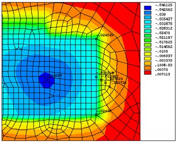
Fig. 13Effect of new building on three-story building
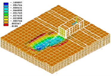
Fig. 14Draft base in left upper corner of building (in meters)
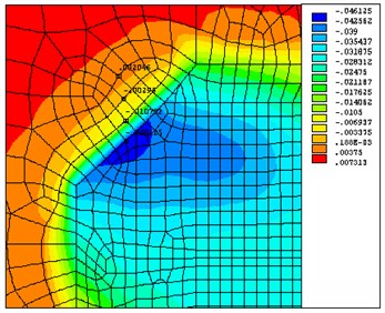
Fig. 15Effect of new building on five-story building
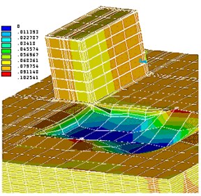
The results of calculation of displacements at the base of the lower edge of the foundation plate under the hob and in the neighboring regions, shown in Fig. 12 and 14, showed that the sediment base "died" at a distance of about 1.5-2.5 m from the edge of the plate and had an impact on neighboring buildings: three-story building, directly adjacent to the designed building and five-story building.
Process solutions in connection with a large volume (the system of the order of 100 thousand equations) were divided into two parts, i.e. impact of the expected settlement of a new building was considered separately in the three-story building (Fig. 13) and a five-story building (Fig. 15).
Existing buildings, together with the foundation, were modeled with spatial 8-node finite elements, excluding window and door openings.
5. Conclusions
An analysis of the calculation results showed the need to strengthen the foundation of a three-story building (according to the results of numerical studies, summing plate amplification was suggested) and the near corner of the five-story building (it was proposed to strengthen concrete clip of the corner).
The results of numerical experiments in the project and the training materials were handed over to the construction industry and implemented in the project development at home, thus reducing the consumption of materials and building structures to ensure the safety of existing buildings.
A numerical model of holistic structure was diacoptically dismembered on the ground part of the structure, foundation. Mathematical models were constructed, and software and tools were developed for an objective computer simulation state of stress of all parts and components facilities. This powerful device simulation of the dynamic state of the whole structure of the building under the influence of various external disturbances allows with the sufficient accuracy predicting the structure of the viability and ensuring the safety of the building residents.
References
-
Perel'muter A. V., Slivker V. I. Computational Models of Structures and Possibility of Their Analysis. Publishing House Steel, Kiev, 2002, p. 600, (in Russian).
-
Kashevarova G. G., Permjakova T. B. Numerical Methods for Solving Construction Tasks on a Computer: Manual. Perm, 2003, p. 352, (in Russian).
-
Bartholomew L. A. Forecast Pellet Plants Based Collaborative Base, Foundation and Surface Structures. Perm State Technical University, Perm, 1999, p. 147, (in Russian).
-
Andrews J., McLawn R. Mathematical Modeling. Mir, Moscow, 1979, p. 250, (in Russian).
-
Basov K. A. ANSYS in the Examples and Problems. Computer Press, 2002, p. 224, (in Russian).
-
Rosin L. A. The Finite Element Method in the Annex to the Elastic System. Stroyizdat, 1977, p. 424, (in Russian).
-
Strang G., Fix J. The Theory of Finite Element Method. Mir, 1977, p. 349, (in Russian).
-
Pobedria B. E. Numerical Methods in the Theory of Elasticity and Plasticity: Proc. Allowance. Publishing House of Moscow University, 1995, p. 366, (in Russian).
-
Fadeev A. B., Matveenko G. A. Semi-analytical finite element method for solving spatial problems of foundation in the elastic and elastoplastic formulation. Proceedings of the Universities. Construction and Architecture, Vol. 12, 1988, p. 113-116, (in Russian).
-
Gorbunov-Passadov M. I., Malikova T. A., Solomin V. I. Calculation of Structures on Elastic Foundation. Stroyizdat, 1984, p. 679, (in Russian).
-
Durayev A. E. Calculation of Structures on Elastic Foundation with an Increasing Strain on the Unit Depth. Publishing House of Mordovia University Press, Saransk, 1991, p. 192, (in Russian).
-
Zubchaninov V. G. Fundamentals of the Theory of Elasticity and Plasticity. Higher School, 1990, p. 368, (in Russian).
-
Alikin V. N., Anokhin P. V., Kolmogorov G. L., Litvin I. E. Strength Criteria and Calculation of Mechanical Reliability Designs. Perm State Technical University, Perm, 1999, p. 158, (in Russian).
-
Aleynikov C. M. The Boundary Element Method in Contact Problems for Elastic Spatially Inhomogeneous Grounds. Publishing House of the DIA, 2000, p. 754, (in Russian).
-
Andreev V. I. Some Problems and Methods of Mechanics of Heterogeneous Media. ASV, 2002, p. 288, (in Russian).
-
Abelian M. Y. Accidents Structures Foundations. Publisher Moscow Engineering and Construction, 1975, p. 184, (in Russian).
-
Sotnikov S. N. By assessing the validity of the results of the calculation of the final draft grounds of buildings. The Construction and Reconstruction of the Bases on Soft Ground. SPbISI, St. Petersburg, 1992, p. 5-13, (in Russian).
-
Chigarev A. V., Kravchuk A. S., Smalyuk A. F. ANSYS to Engineers. Reference Manual. Mechanical Engineering, 2004, p. 512, (in Russian).
-
ANSYS Basic Analysis Procedures Guide. Release 5.6. ANSYS Inc., 1998.
-
Lyalin V. E., Dybrin A. A. Development and application of computational technology for solving the space problem of integration of the new building into the existing building. News TSU. Series. Mathematics. Mechanics. Computer Science. Informatics. Tula State University Publishing House, Tula, Vol. 12, Issue 4, 2006, p. 318-336, (in Russian).
