Abstract
The article discusses the use of finite element models of structures in the reconstruction of buildings, located in built-up areas with complex hydrogeological and landscape territorial state. The verification of a mathematical model based on the construction of a natural experiment of deformation and destruction of the existing structure, taking into account changes in lithological soil conditions.
1. Verification of finite element model of building, taking into account changes in lithological soil conditions
The object of study is a five-story residential brick building. According to the results of geological subsoil surveys for the construction period it is homogeneous to a depth of 12 m. The building is a typical implementation project of 1-447S series. A few years later, a through crack of settlement origin appeared on the eastern facade along the entire height of the building. As a result of visual and instrumental observations of the building throughout the year, it was found that the building walls got a relative differential settlement from 2 to 4 mm. The results showed that it caused by rainfalls at home over the next year and continued unevenly (movement was 4-8 mm) but there were no visible damages of the building walls. After a decade in the walls on the perimeter of the building, we revealed cracks of various widths (especially near the stairwells) in places which dislocations are shown in Fig. 1.
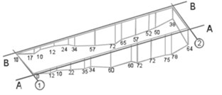
Values u(i)z of settlement along the walls of the house are shown in Fig. 2. The maximum rainfall foundation thus amounted to 72 mm. With a further increase in their risk of destruction of load-bearing walls, you want to assume the regulated measures for the preservation of their further destruction.
Fig. 1Cracks in facade on axis A-A
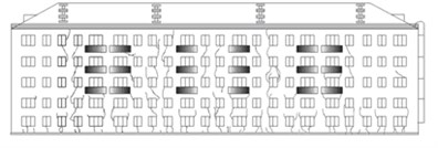
Fig. 2Actual precipitation foundation (in mm)
Carried out geological surveys have shown changes in properties of the soil under the building and adjacent buildings (measurements were carried out in the foundation base plane). It formed three zones with different properties.
Theoretical studies were carried out in two stages [1]: Stage 1 – Modelling the structure of the system, foundation and soil and calculation of the stress-strain state of the system, taking into account the changed properties of the base (soil heterogeneity); Stage 2 – Calculation of stress-strain state (SSS), a five-story brick building on the foundation and operation of its own weight and kinematic effects in the form of non-uniform building deposits in nonlinear statement.
The model takes into account all load-bearing structures and overlap with the actual size of all openings of windows and bridges.
Fig. 3Calculated and actual rainfall along building length: a) on axis A-A, b) on axis B-B; × – actual rainfall; ▲, ■ – theoretical rainfall boundary conditions
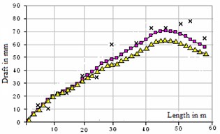
a)
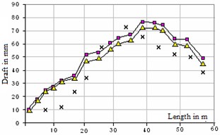
b)
Doorways and staircases in the model are not included due to their small weight compared to the weight bearing structures and floors (floors contain heavy partitions). Gable roof and balcony slab is not included in the model building (an extra layer of coating was introduced for its account). Strip foundation model has true dimensions.
As a result of the implementation of numerical values obtained by the calculation of the building sediment basement at different variants of soil array fixing, which are shown in Fig. 3. Here, the marking of the actual pellet resulting observations is available.
The second phase precipitates the calculated actual foundation (Fig. 2) using the previously considered possible state models of elastically brittle construction materials.
Fig. 4Movements uz, m
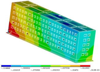
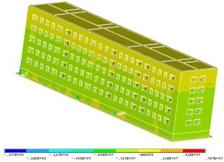
Fig. 7Stress σz, Pa
The boundary conditions for this problem are of the form:
uz(→x)=U,ux(→x)=uy(→x)=0,
where z = –1.8 (on the sole foundation); →x – radius vector of the spatial position of the finite element faces Г2∪Г4∪Г5∪Г6∪Г7 define building walls and roof.
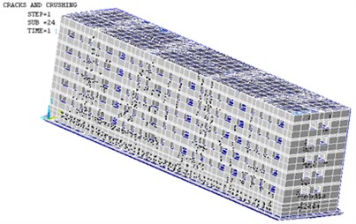
The numerical solution of the nonlinear problem was based on the finite element method using a stepwise procedure. At each step of the solution for convergence, the equilibrium iteration was carried out using the Newton-Raphson method. As a result, the decision determined the stress-strain state of the load-bearing structure of the building with dislocated fractures (Figs. 4-7) and got cracking localization scheme in the building walls identical to the real picture of the destruction (Fig. 8).
An analysis of the results leads to the conclusion that the appearance of cracks on the facade of the building was really caused by differential settlement of the foundation, which in turn was the result of a local deterioration of the soil mass. We can assume that the constructed three-dimensional model of the structure of the system, the foundation and the soil is adequate to the real system and can be used to analyze the SSS similar structures. The rules of designing buildings and structures do not exclude the possibility of visiting the carrying and enclosing constructions of deformations and cracks permitted by operating conditions and disposable in making repairs. In order to prevent the emergence of new cracks and for strengthening of the existing soil hardness, the carburizing is provided at great depths.
Fig. 8Picture propagation of cracks in load-bearing walls of building
2. Computational experiments.
Simulation projects secure the reconstruction of existing buildings located on the territory of karst. A reconstruction Project of a two-story brick building, which is supposed to have a superstructure of an attic, the extension of a staircase on one side of the building, the addition of a new building on the other side. It is necessary to consider the possibility of reaching the surface sinks, i.e. to ensure the safety of reconstruction on karst areas.
In solving this problem 3 tasks have been solved:
1. Identify additional rainfall [4] as a result of constructions and building out an analysis of the stress-strain state of the building and the foundation;
2. Analyze the stress-strain state of the system structure taking into account the occurrence of sinkholes;
3. The numerical analysis of the stress and strain reinforced foundation base of the structure.
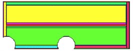
It was modeled after the appearance of two sinkholes [2, 3], the most unfavorable location of which is shown in the diagram in Fig. 9. One in the most dangerous place is the corner of the building (at the junction with the annex), the second one is in the center beneath the foundations of the existing building.
Fig. 9Scheme of sinkholes under foundation
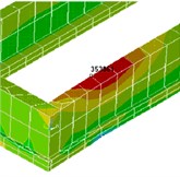
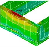
The calculations show that a margin of safety foundation is sufficient to sustain the appearance of karst funnel in the central part of the building, but the Karst at an angle at the point of contiguity outhouse is extremely dangerous. Additional rainfalls after the appearance of sinkholes are small and do not exceed the value of 4 cm, which is less than the limit value of 10 cm. However, tensile stresses in the concrete of the foundation are up to 3.54 MPa with respect to x-axis and 4.97 MPa on the y-axis (attic, annex) (Fig. 10), that exceeds the limit values (0.9 MPa). Stresses in the masonry wall along the axes x and y do not exceed the limits, provided that there are no cracks in the concrete.
Given these results and the fact that it is impossible to accurately predict the point where they exit sinkhole on the surface, it is necessary to strengthen the existing foundation. As a result of numerical experiments to identify options for strengthening a concrete frame in increments of 3 m and a rib width of 1 m (Fig. 11).
Fig. 10Maximum stress values (Pa) in base after formation of sinkholes (including attic and attachment) a) towards x-axis, b) towards y-axis
a)
b)
Fig. 11Reinforced concrete frame of foundation strengthening
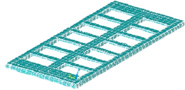
After this option selection, the gain was compared with the conventional continuous slab gain due to the fact that, even in the worst case, it will cover only 10 % of plate area. The framework will be used as ~30 %, and will redistribute stress from the end of the building. In addition, the frame structure requires less staff time and less material consumption.
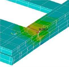
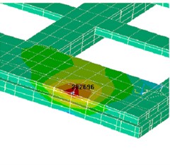
The numerical results showed that the tensile stresses arose with entirely perceived reinforcement. The maximum stresses gain in carcass reinforcement is a considerably lower limit (Fig. 12). The redistribution of stresses will reduce the effort in the end walls more than two times. Concrete cracks after the initial disclosure and the redistribution of stress on the reinforcement were fully closed.
Fig. 12Maximum stress (Pa) in carcass reinforcement of foundation (including sinkholes, attic and attachment): a) towards x-axis, b) towards y-axis
a)
b)
3. Mathematical modeling and numerical simulation of spatial structure of building.
The article deals with a mathematical modeling and numerical simulation of the spatial structure of buildings as an objective criterion for projects of reconstruction of foundations and structures, built on a difficult terrain. On the outer walls of a two-story building a reinforced belt in two levels should be provided. It is the structure of existing foundations – belt (speed adjustment of laying the scheme with a reduction in the sole marks in the direction of the ground slope) of the foundation blocks (concrete B15), laid on monolithic concrete pad on a natural basis. The foundation consists of fluid-plastic and soft-plastic clays. A numerical model of a standard engineering solution of base strengthening of the existing foundation in the northern corner of the building bored piles.
In this area, two problems were solved:
1. The calculation of settlement and the bearing capacity of the foundation and the building, taking into account the gain ground of bored piles (reinforced soil characteristics are taken from the survey report);
2. The same, but without reinforced soil.
The study subject was four-layer soil of different thickness with averaged properties, with a total thickness of 15 m, lying below the lower surface of the concrete foundation. Subgrade properties were taken from materials of engineering and geological surveys.
The calculation took into account the following values: load from the dead weight of the building, the weight of roof structures - as a surface load of 100.78 kg/m2; Temporary load: wind, snow and useful to overlap.
Fig. 13Driving building settlement considering strengthening of foundation, m
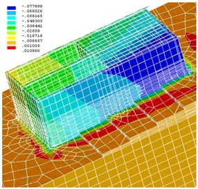
Fig. 14Precipitation of building, m (enlargement of foundation)
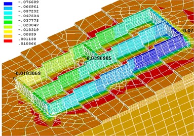
The problem of determining the stress-strain state of the structure of the system, foundation and soil was solved by the finite element method using a non-linear Drucker-Prager model. For a sampling of three-dimensional areas (foundations, foundation, structural elements of buildings), three-dimensional finite elements with eight-nodal first order hexagonal configuration and six-nodal ones with five-sided configuration were used. Window openings are not modeled. A program of construction and calculation of the structure of the system, foundation and soil on the APDL language and obtained results of the solution are the tensor components of stress and strain. Figs. 13 and 14 show the vertical moving system in meters obtained by solving the first problem (with power ground).
The maximum foundation settlement was found to be 7.5 cm, and the difference between the parts of the foundation settlement was ~6.5 cm. Thus, the maximum foundation settlement smax = 7.5 does not exceed the limit of average rainfall as per “Construction Standards and Regulations” [4] 15 cm, the relative difference between the value of the residue Δs/L = 6.5/2860 = 0.00227 does not exceed the limit of the relative difference of settlement of 0.0024.
Thus, as shown by the results of computational experiments, the proposed increase in only one part of the building does not ensure the desired result: the values of settlement do not change, and only their form changes. This is due to the stepped design of the foundation, which does not have sufficient rigidity, which leads to a displacement of the structure relative to the horizontal axis. The strengthening of the building in the lower right corner leads to upsetting the upstream part of the building structure, as structure tends to a more sustainable position. The spatial structure of the numerical model of the system, foundation and soil, taking into account all types of loads and ground features allows predicting the actual nature of the settlement and allows predicting the need for strengthening the foundation.
The analysis of the stress state of construction designs showed that the bearing walls and foundation of the building of the test stresses do not exceed the permissible values, and the walls are in relative safety. Concrete belt gain almost completely unloads the building walls.
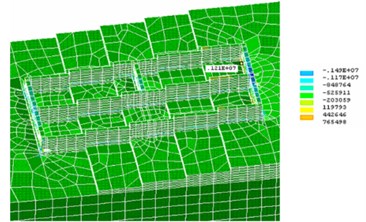
The soil (fluid-plastic clay is weak compressible) in some of the most dangerous places has large tensile stresses (Figs. 16 and 17), exceeding the carrying capacity of the soil, and ground buckling, which in turn can lead to the destruction of concrete preparation floor basement, can occur. For the perception of these strains, it was suggested to introduce the reinforcement mesh.
Fig. 16Stresses (Pa), resulting in construction of foundation and basis for x-axis
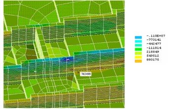
Fig. 17Stresses (Pa), resulting in construction of foundation and basis for y-axis
4. Conclusions
Using a retrospective analysis of cracking reasons in the bearing walls of brick buildings, we showed how adequate the developed mathematical model of deformation and destruction of the space system “building-base-foundation” was, which took into account the process of structural damage and strain softening.
With the help of numerical studies, we found a possible solution to the three-dimensional problem of the safe designing and reconstruction of the superstructure facilities in the karst area, taking into account the access to the surface of sinkholes which has also been substantiated by design options that enhance the facility.
The method of computing experiment made the forecast change in the stress-strain state of the foundation and structure, stationed in karst areas, with stationary and extreme dynamic and kinematic perturbations.
References
-
Danilov V. I., Lyalin V. E. Verification of a mathematical model based on the construction of full-scale experiment deformation and destruction of the existing structure, taking into account changes in lithological soil conditions. Scientific and Practical Journal “Intelligent Systems in Production”, Vol. 2, 2013, p. 142-154, (in Russian).
-
Danilov V. I., Kashevarova G. G. Simulation projects secure the reconstruction of existing buildings located on the territory of karst. Proceedings of the International Correspondence Scientific – Practical Conference “Current Research Trends of the XXI Century: Theory and Practice”, Voronezh, 2013, p. 113-115, (in Russian).
-
Danilov V. I., Lyalinv E. Simulation Projects Secure the Reconstruction of Existing Buildings Located on Areas of Karst, Subject to Building Out Design. Vestnik Kalashnikov Izhevsk State Technical University, Izhevsk, Vol. 4, Issue 60, 2013, p. 188-192, (in Russian).
-
Danilov V. I., Kashevarova G. G. Identification of additional soil and settlement change of the stress-strain state of the foundation and structure of the constructed extensions. Materials XIII International Scientific-Practical Conference “Prospects of Development of Information Technologies”, Novosibirsk, 2013, p. 59-63, (in Russian).
-
Perel'muter A. V., Slivker V. I. Computational Models of Structures and Their Analysis Possibility. Publishing House “Steel”, Kiev, 2002, p. 600, (in Russian).
-
Andrews J., McLawn R. Mathematical Modeling. Mir, Moscow, 1979, p. 250, (in Russian).
-
Strang G., Fix J. An Analysis of the Finite Element Method. Wellesley Cambridge Press, 1973, p. 306.
