Abstract
Studied on the flywheel micro vibration isolator of a space telescope, the relationship between input and output (I-O) disturbance force and velocity vector is described by the characteristic transfer matrix in the subsystem of the flywheel vibration isolation. The elastic support coupling vibration transfer matrix of the vibration isolator is derived, and the vibration transfer characteristics of the vibration isolation system are studied. The dynamic model of the three degrees coupled vibration isolation system about the flywheel micro vibration excitation, multi elastic support and basic structure is established on the admittance method and partition subsystem. Model simulation and the flywheel vibration isolation system test results show that the two spectra are consistent basically in the frequency components, the form of vortex frequency curve and the change of amplitude, which indicates that the key factors of the vibration characteristics of the flywheel vibration isolation system are accurate and the theoretical analysis is correct. The sub structure analysis method effectively avoids the complexity of the solution of the state vector of the sub structure coupling interface. The elastic support coupled vibration transfer matrix can solve the problem of the sub structure integration and merging, and integrated modeling and analysis in active and passive support system.
1. Introductions
Attitude control actuator is the core technology of the precision and high stability space telescope [1, 2]. Flywheel as attitude control and attitude stabilization equipment in space telescope, it will generate additional disturbance force and torque when spins on orbit, which will affect the accuracy, stability, and imaging quality of the telescope [3, 4].
Micro vibration on the influence of the payload is more complex, which involves structure, control and optical system. Integrated modeling technology is an effective analysis method. It refers to that on the basis of the structure, control and load system modeling, according to the physical connection of the micro vibration in the transmission path of each subsystem, the system model is integrated. And a system level dynamic I-O mathematical model, which can fully reflect the influence of various coupling effects on the key performance indicators of the spacecraft, is finally formed. Many research institutes have made a research on the integrated modeling system in the world. NASA established a model of Integrated Modeling Environment [5].United States Air Jet Propulsion Laboratory established the Integrated Modeling of Optical Systems [6]. Massachusetts Institute of Technology established the Disturbance Optics Controls Structures [7]. They provide system level comprehensive performance evaluation and error analysis methods, which have been successfully applied to the development of high resolution space telescope JWST [8], SIM [9] and TPF [10]. Luo Q., Li D. and Zhou W. addressed the dynamic modeling and analysis of the micro-vibration isolation of flywheel assemblies [11]. Yu J., Yamaura H., Oishi T., et al focused on vibrations caused by loading torque of printing mediums when they were delivered into the machinery. The system was modeled as a four-rollers-belt with a stepper motor based on exist apparatus [12]. By considering the flywheel and the platform as an integral system with gyroscopic effects, Wei Z., Li D., Luo Q., et al developed an equivalent dynamic model and verified through eigenvalue and frequency response analysis [13].
The above literatures on the micro vibration of the flywheel are mainly integrated modeling. Modeling of the transmission characteristics of the flywheel vibration isolator is not carried out. In this paper, the dynamic model of the three degrees coupled vibration isolation system about the flywheel micro vibration excitation, multi-elastic support and basic structure is established on the admittance method and partition subsystem. The relationship between I-O disturbance force and velocity vector is described by the characteristic transfer matrix in the subsystem of the flywheel vibration isolation.
According to the structure parameters and the micro vibration characteristics of a certain type of flywheel, the model is simulated to obtain the output vibration power waterfall plot. We got the flywheel vibration isolation system waterfall plot as well by testing the flywheel isolation system using multi component device. The results indicated that the key factors of the vibration characteristics of the flywheel vibration isolation system are accurate and the theoretical analysis is correct.
2. Flywheel vibration isolation system model
The flywheel vibration isolator adopts four points supporting symmetrical radiation type arrangement and the vibration isolation device is arranged in a radiation pattern, which is shown in Fig. 1. Along with the coupling structure department, the flywheel isolation system is divided into three subsystems, including source quality A, isolation vibration bearing B, and supporting basic C. Each subsystem represents one or more rigid distributed parameter components of the total system. The rigid element has six degrees of freedom, and the structure of the distributed parameter is allowed to be more than one degree of freedom. According to the direction of the energy flow, the system force and velocity vectors of I-O terminals are defined, and the overall characteristic transfer matrix model of the system is established, which is shown in Fig. 2. Each transfer structure represents a subsystem of the whole system.
Fig. 1Flywheel vibration isolation system
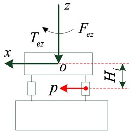
a) Face view of vibration isolation system
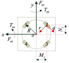
b) Top view of vibration isolation system
Fig. 2Dynamic characteristic transfer matrix model of vibration isolation system
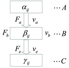
The I-O state vectors of each subsystem and the characteristic matrix αij, βij, γij constitute the basic integrated unit of the analysis model transfer matrix.
3. Coupled vibration transfer characteristics
3.1. Flywheel sub-structure disturbance characteristic transfer matrix
The natural frequency of the flywheel is much larger than that of the disturbed excitation frequency, so it can be regarded as a general three-dimensional rigid structure. Fe is expressed as the generalized disturbance force vector acting on the flywheel centroid, ve is the generalized velocity response vector of the flywheel centroid. The generalized force and the velocity vector of the flywheel disturbance output, which connected with subsystem through n (n=4) coupling point, are Fa and va:
ve=[vexveyvez˙θex˙θey˙θez]T,
Fa=[F1aF2a⋯Fna]T,va=[v1av2a⋯vna]T.
According to the law of dynamics and structure geometry relation, the translational and rotational motion equations of the micro vibration source of the flywheel, under the generalized harmonic exciting force [14], are expressed as Eq. (2) in the form of admittance matrix [15]:
where, the element matrixes Mij are:
where, J represents the inertia diagonal matrix of the flywheel centroid, w is the exciting frequency, j=√-1.
TF is the mass output vector of micro vibration and TV is the generalized vector of centroid, which are under rigid constraint conditions:
Combined the I-O state vectors of the micro vibration source mass, the Eq. (2) is transformed into Eq. (9):
The characteristic transfer matrix αij is derived from the admittance matrix, which is expressed as Eq. (10):
3.2. Vibration isolator characteristics
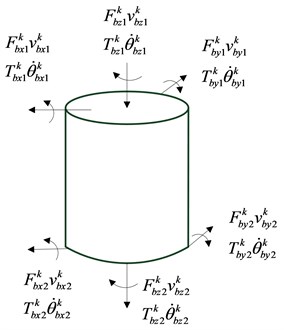
The flywheel vibration isolator is modeled [16] as a cylindrical continuous elastic rod with a density ρ and damping η. A dynamic model of multi input and multi output structure is established, which is shown in Fig. 3.
In Fig. 3, the generalized force and velocity response vectors of the I-O terminals are:
vkb1=[vkb1xvkb1yvkb1z˙θkb1x˙θkb1y˙θkb1z]T,
Fkb2=[Fkb2xFkb2yFkb2zTkb2xTkb2yTkb2z]T,
vkb2=[vkb2xvkb2yvkb2z˙θkb2x˙θkb2y˙θkb2z]T.
The transfer matrix equation for the dynamic characteristic of the vibration isolation system is Eq. (12):
where, Bkij is the three-dimensional coupling vibration isolator transfer matrix, which can be determined by structural generalized admittance frequency response function [17] based on modal analysis[18, 19]. The detailed derivation process is as follows.
As shown in Fig. 3, the I-O force and moment are Fby1, Fbz1, Tbx1 and Fby2, Fbz2, Tbx2. We can get the transfer admittance frequency response function by modal analysis method:
Rvby1Tbx1=-jwηsinhλfh⋅sinhλfhE*σIλ2f(cosλfhcoshλfh-1),Rvby2Tbx2=-Rvby1Tbx1,
Rvbz1Fbz1=-jwηcosλ1hAE*σλ1sinλ1h,Rvbx2Fbz2=Rvbz1Fbz1,
R˙θbx1Fby1=Rvby1Tbx1,R˙θbx2Fby2=-R˙θbx1Fby1,
R˙θbx2Tbx2=jwηcosλfhsinhλfh+sinλfhcoshλfhE*σIλf(cosλfhcoshλfh-1),R˙θbx2Tbx2=R˙θbx2Tbx2,
Rvby2Fby1=jwηsinλfh-sinhλfhE*σIλ3f(cosλfhcoshλfh-1),Rvby1Fby2=Rvby2Fby1,
Rvby2Tbx1=-jwηcosλfh-coshλfhE*σIλ2f(cosλfhcoshλfh-1),Rvby1Tbx2=-Rvby2Tbx1,
Rvbz2Fbz1=-jwη1AE*σλ1sinλ1h,Rvbz1Fbz2=Rvbz2Fbz1,
R˙θbx2Fby1=-Rvby2Tbx1,R˙θbx1Fby2=-R˙θbx2Fby1,
R˙θbx2Tbx1=jwηsinλfh+sinhλfhE*σIλf(cosλfhcoshλfh-1),R˙θbx1Tbx2=R˙θbx2Tbx1,
where, λf is the structure bending wave number, λ1 is longitudinal wave complex wave number. h is supporting structure height, A is section area and I is moment of inertia. E*σ is the elastic modulus.
Considering the coupling relationship between I-O of each motion component, the vibration isolation support characteristic transfer matrix ¯Bij for the symmetry plane Oyz is derived, which is shown as follows:
T12=[Rvby1Fby20Rvby1Tbx20Rvbz1Fbz20R˙θbx1Fby20R˙θbx1Tbx2],
T21=[Rvby2Fby10Rvby2Tbx10Rvb2z2Fb1z10R˙θbx2Fby10R˙θbx2Tbx1],
T22=[Rvby2Fby20Rvby2Tbx20Rvbz2Fbz20R˙θbx2Fby20R˙θbx2Tbx2].
In the same way, the state vector transfer matrix ˆBij of Oxz plane can be determined.
Integrated vibration isolation support I-O state vector Fb1, vb1, Fb2, vb2 and the matrix ¯Bij, ˆΒij, the elastic support coupling vibration transfer matrix Bij are shown as follows:
Γ3=sinλfh+sinhλfh,Γ4=cosλfh-coshλfh.
Fig. 3Coupled vibration mechanics model
3.3. Honeycomb panel structure characteristic matrix
The flywheel is installed on the honeycomb panel of the telescope structure, for the convenience of research, the honeycomb board structure is modeled as a rectangular plate, and the admittance matrix equation of the structure characteristic is described as Eq. (21):
where, Fc is the input generalized force of each support structure, and vc is the velocity corresponding response vector. The characteristic matrix can be determined by the modal analysis method [7, 14, 15]:
4. Coupling system vibration characteristic transfer matrix
According subsystem coupled junction force and displacement continuity conditions, the dynamic characteristics of a comprehensive subsystem above matrix Eqs. (9), (18), (21), we get the state vector in overall system coupling interface:
The element matrix of the system characteristic transfer matrix Λij is:
5. Model simulation and experiments
5.1. Model simulation
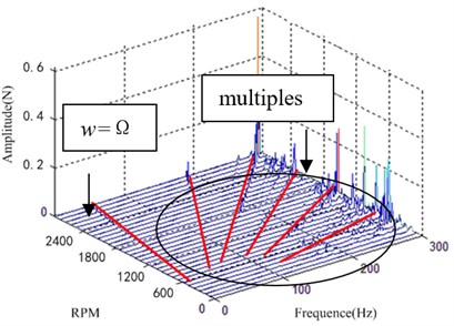
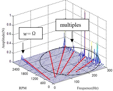
According to the flywheel structure parameters and vibration isolator micro vibration features which are provided by the manufacturers. The parameters are shown in Table 1, and the parameters of the honeycomb panel are shown in Table 2, and the layer mode of the honeycomb panel is shown in Fig. 4. The model in Chapter 2 was simulated under the flywheel imbalance condition. The output disturbance force waterfall plot is shown in Fig. 5.
Table 1Parameters of vibration isolation system
Substructure | Parameters | |
Flywheel | m, Jx | 2.71 kg, 0.0169 kg·m2 |
Vibration isolator | D×d×h | 35 mm×16 mm×12 mm |
E, ρ, η | 6.5 MPa, 1400 kg/m3, 0.09 | |
Honeycomb panel | a×b×c | 1298 mm×1199 mm×24.4 mm |
Fig. 4The layer mode of the honeycomb panel
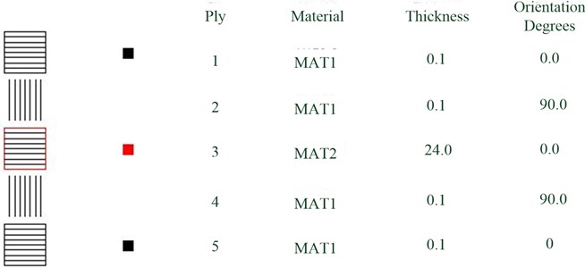
Table 2Parameters of the honeycomb panel
Material | E1 (MPa) | E2 (MPa) | Nu | G12 (MPa) | G1Z (MPa) | G2Z (MPa) | ρ (kg/m3) |
MAT1 | 620000 | 7400 | 0.29 | 4300 | 4300 | 4300 | 9.44E-09 |
MAT2 | 0.005 | 0.005 | 0.29 | 0.001 | 37.5 | 25 | 1.78E-11 |
Fig. 5Model simulation waterfall plot
a)X axis
b)Z axis
5.2. Flywheel vibration isolation system experiments
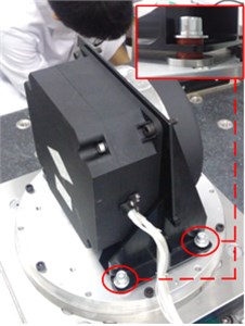
The disturbance test is carried out in the ultra-clean environment laboratory. The test site is shown in Fig. 6. Using the six component quartz model HR-FP3402 force plate, the sensor sampling frequency is 5000 Hz, testing the flywheel disturbing force characteristics in the X-axis and Z-axis. Testing process is speed up the flywheel from 0 RPM (Rotation per minute) to the specified speed, deceleration to 0 RPM after holding 20 s, a single total test time 60 s, and the single test time lasts 60 s.
Signal processing the disturbance data in the stable speed at different speed, the waterfall plot curve of the characteristics in frequency domain is shown in Fig. 7.
Fig. 6Experiments site
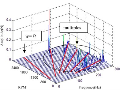
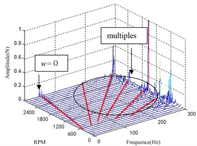
According to Fig. 7, at the same frequency of the vibration isolation system the flywheel has scrambled excitation force, and there are also a series of harmonics at multiples. In addition to the individual frequency points, the X axis disturbance force of the vibration isolation system is in the 0.1 N magnitude, and the Z axis disturbance force of the vibration isolation system is in the 0.2 N magnitude.
Fig. 7Experiment results waterfall plot
a)X axis
b)Z axis
5.3. Result discussion
The Fig. 4 and Fig. 6 show that the two spectra are consistent basically in the frequency components, the form of vortex frequency curve and the change of amplitude. The vibration disturbance force exists in the frequency shown the first line in Fig. 4 and Fig. 6, which is caused by the unbalance of the flywheel. Consistent with the actual working conditions of the flywheel, a series of harmonic is also caused by the flywheel rotating frequency at high frequency.
The test result in Fig. 6 shows amplification of x-direction disturbance around 200 Hz which is not captured in the simulation. This vibration of the flywheel is caused by the modal enlargement of the supporting structure. Structural modal amplification factors are more complex, in this paper, the process of modeling and Simulation is not considered. So, there is no significant amplitude appears x-waterfall plot around 200 Hz in Fig. 4. The experimental results show that the modal amplification effect of the flywheel is obvious, and it needed to be modeled separately due to the complexity of the structural mode amplification effect.
The amplitude of the disturbance is significant around 294 Hz in Fig. 4 and Fig. 6, it is the obvious characteristics of the flywheel whirl mode, which is caused by flywheel axial translational mode and radial translational mode. Analysis and test results also show that when the natural frequency of the flywheel and the harmonic frequency of the intersection, it will produce a significant resonance, resulting in disturbance amplification, especially around 270 Hz.
Although the simulation results and experimental results are in error, the theoretical modeling and simulation analysis match well with the experimental results, which indicates that the key factors of the vibration characteristics of the flywheel vibration isolation system are accurate and the theoretical analysis is correct.
6. Conclusions
In this paper, the dynamic model of the three degrees coupled vibration isolation system about the flywheel micro vibration excitation, multi elastic support and basic structure is established on the admittance method and partition subsystem. The relationship between I-O disturbance force and velocity vector is described by the characteristic transfer matrix in the subsystem of the flywheel vibration isolation.
1) Model simulation and the flywheel vibration isolation system test results show that the two spectra are consistent basically in the frequency components, the form of vortex frequency curve and the change of amplitude, which indicates that the key factors of the vibration characteristics of the flywheel vibration isolation system are accurate and the theoretical analysis is correct.
2) Three-dimensional coupled micro vibration transfer matrix dynamic model shows that the transfer matrix method can effectively avoid the complexity of the solution of the state vector of the sub structure coupling interface. This method can be applied to the vibration analysis of multi – layer or multi – system with branches.
3) Transfer matrix can play a more prevalent role in the study of dynamic characteristics of micro vibration isolation system, active and passive control integrated modeling and analysis, at the same time, it establishes the theoretical basis for the structural parameters optimization and active control strategy of the flywheel micro vibration system.
References
-
Tian L., Xu S. Attitude control considering variable input saturation limit for a spacecraft equipped with flywheels. Chinese Journal of Aeronautics, Vol. 25, 2012, p. 437-445.
-
Yang Zh., Yang N., Yu Y. Earth-observation satellite attitude control using passive and active hybrid magnetically suspended flywheels. Journal of Beijing Institute of Technology, Vol. 23, Issue 2, 2014, p. 226-234.
-
Jin L., Xu S. J. Underactuated spacecraft angular velocity stabilization and three-axis attitude stabilization using two single gimbal control moment gyros. Acta Mechanica Sinica, Vol. 26, Issue 2, 2010, p. 279-288.
-
Grega R., Baran P. Pneumatic Dual Mass Flywheel-Damper Concept for Down Speeding. The Latest Methods of Construction Design. Springer International Publishing, 2016, p. 361-367.
-
Ujhelyi Z., Bergmann G., Hegedüs Á., et al. An integrated development environment for live model queries. Science of Computer Programming, Vol. 98, 2015, p. 80-99.
-
Sung J. H., Esch M. B., Prot J. M., et al. Microfabricated mammalian organ systems and their integration into models of whole animals and humans. Lab on a Chip, Vol. 13, Issue 7, 2013, p. 1201-1212.
-
Miller D. W., De Weck O. L., Mosier G. E. Framework for multidisciplinary integrated modeling and analysis of space telescopes. Proceedings of SPIE, Vol. 4757, 2002, p. 1-18.
-
Mosier G. E., Howard J. M., Johnston J. D., et al. The role of integrated modeling in the design and verification of the James Webb space telescope. Proceedings of SPIE, Denver, Vol. 5528, 2004, p. 96-107.
-
Miller D. W., de Weck O. L., Uebelhart S. A., et al. Integrated dynamics and controls modeling for the space interferometry mission (SIM). IEEE Aerospace Conference Proceedings, Big Sky, MT, Vol. 4, 2012, p. 2001-2089.
-
LoBosco D. M., Blaurock C., Chung Soon-Jo, et al. Integrated modeling of optical performance for the terrestrial planet finder structurally connected interferometer. Proceedings of SPIE, Glasgow, Scotland, Vol. 5497, 2004, p. 278-289.
-
Luo Q., Li D., Zhou W. Studies on vibration isolation for a multiple flywheel system in variable configurations. Journal of Vibration and Control, Vol. 21, Issue 1, 2015, p. 105-123.
-
Yu J., Yamaura H., Oishi T., et al. Vibrations suppression control of image transfer belt system with flywheel or dynamic vibration absorber. Journal of Advanced Mechanical Design, Systems, and Manufacturing, Vol. 7, Issue 1, 2013, p. 52-64.
-
Wei Z., Li D., Luo Q., et al. Modeling and analysis of a flywheel micro vibration isolation system for spacecrafts. Advances in Space Research, Vol. 55, Issue 2, 2015, p. 761-777.
-
Avitabile P. Experimental modal analysis. Sound and Vibration, Vol. 35, Issue 1, 2001, p. 20-31.
-
Lee Y. S., Choi M. H., Kim J. H. Free vibrations of laminated composite cylindrical shells with an interior rectangular plate. Journal of Sound and Vibration, Vol. 265, Issue 4, 2003, p. 795-817.
-
Hossdorf H. Model Analysis of Structures. Van Norstrand Reinhold Co., New York, 1971.
-
Stanef D. A., Hansen C. H., Morgans R. C. Active control analysis of mining vehicle cabin noise using finite element modelling. Journal of Sound and Vibration, Vol. 277, Issue 1, 2004, p. 277-297.
-
Moaveni B., Stavridis A., Lombaert G., et al. Finite-element model updating for assessment of progressive damage in a 3-story infilled RC frame. Journal of Structural Engineering, Vol. 139, Issue 10, 2012, p. 1665-1674.
-
Luo Q, Li D, Jiang J. Analysis and optimization of microvibration isolation for multiple flywheel systems of spacecraft. AIAA Journal, 2016, p. 1719-1731.
About this article
The authors would like to thank the financial support of The National Natural Science Foundation of China (No. 41501383).

