Abstract
To reduce the torsional vibration of vehicle power transmission system (VPTS), a torsional vibration model with multiple degrees of freedom (multi-DOFs) of VPTS was established for reasonable parameter selection of the torsional vibration damper (TVD) and elastic coupling (EC). Several schemes combining TVD and EC on the driveshaft were enacted. Based on this, an optimization model was established to minimize the maximum torsional vibration elastic potential energy (TVEPE) of VPTS. In this model, the torsional stiffness of EC and torsional stiffness and torsional damping coefficient of TVD were chosen as the optimization parameters. After calculation, the optimization results of different schemes were compared and analyzed. Results showed the model incorporating TVD and EC to have a better effect on reducing torsional vibration than TVD after reasonable structure selection and parameter optimization.
1. Introduction
VPTS is a multi-DOFs torsional vibration system (TVS). The main excitation source for TVS comes from the irregular cylinder pressure and the inertial force produced by a crankshaft-connecting rod mechanism. The output torque of the engine is an excitation of superposition of multiple frequency. When the excitation frequency (mainly at the second order) is equal or close to the natural frequency of TVS, the resonance occurs and vibration increases violently, which affects the driving comfort of vehicle considerably and has a significant impact on the durability of components. Requirements of vehicle NVH performance have become increasingly demanding, and the traditional clutch torsion damper can’t fulfill the requirement of torsional vibration reduction; the dual mass flywheel has more excellent effect on reducing torsional vibration than the clutch torsional damper, however, it is too expensive for the production of economical vehicles. It is therefore particularly important to use economical and suitable damping devices in transmission systems.
Because of its lower price and convenient processing, rubber TVD is widely used and has been studied in-depth by many scholars [1-12]. One study presented a method for solving the modal inertia of multi-DOFs vibration model and the parameters optimization of multi-stage TVD [2]. Another discussed the effects of different TVD parameters on energy dissipation, crankshaft torsional vibration amplitude, and the irregularity of crankshaft speed [3]. Ravikant et al. found the optimum position for TVD and flywheel through experiments monitoring the main journal stresses, speed irregularity, torsional amplitudes, and torsional mode [4]. Ebrahimi M. et al. imported multi-speed cylinder pressure curves into the program to optimize the parameters of TVD aimed at reducing the amplitude of crankshaft, and the optimization results were modified using experiments [5]. Mitianiec W. and Buczek K. proved that increasing the inertia of TVD can decrease natural frequencies of a crank train and result in increasing the risk of resonate with low order harmonic of tangential force [6]. Another study investigated the influence of temperature change on torsional stiffness and damping by means of experiments [7]. As engines have developed toward higher speeds and greater power, the suppression of bending-torsional coupled vibration has drawn more and more attention; another study optimized the parameters of TVD while considering the influence of the bending vibration of the crankshaft in nonlinear range [8]. A study of different kinds of coupled vibration damper proved that the suppression of torsional vibration should be considered first [9]. Although these studies were aimed at the suppression of engine vibration, the idea of matching and designing of TVD in the crankshaft is basically similar to the transmission system. The principle of TVD is basically similar to the theory of dynamic shock absorbers, which is that the vibration system should be made to generate anti-resonance. At this time the vibration of the main mass system is limited at natural frequencies. However, the dynamic shock absorber will appear the phenomenon of strong vibration [10-12].
To enhance the damping effect without increasing the inertia of TVD, one-stage TVD can be divided into multiple-stages with fixed total inertia. Another way is to install EC in the TVS. EC can not only compensate for misalignment [13], but also soften impact, reduce vibration, and the change natural frequency of the system [14]. The torsional stiffness and damping coefficient of Geislinger coupling has been shown to change with the excitation frequency, which had a good effect on vibration reduction [15]. However, it has been mainly used in ship power transmission systems and heavy vehicles and only rarely in light vehicles. One study used a transformation matrix to reflect contact stiffness and optimize the evaluation standard of kinematic coupling [16]. The optimization of the structure, material and parameter of coupling has been investigated in many studies [17, 18]. However, studies of coupling for the whole TVS are relatively fewer [19, 20]. The matching of coupling for automotive should be based on the torsional vibration characteristics of the entire transmission system. There have been only a few studies of matching between EC and TVD.
In this paper, the front engine rear wheel drive vehicle is served as a model, and position matching and parameter optimization of EC and TVD are discussed. Through calculation, the reasonable matching of EC and TVD are realized, and the amplitude and maximum TVEPE of VPTS are reduced.
2. Analysis of torsional vibration of VPTS with multi-DOFs
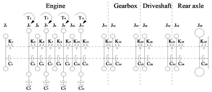
Because the structure of VPTS is complicated, the lumped mass method was used to simplify the system in this paper. The nonlinear factors in the VPTS which have minor effects on the focus problem of resonance were not considered, and the TVS was simulated as a linear model. The forced vibration model of the TVS was established using the excitation source originate from engine output torque. According to the simplified principle and equivalent calculation method [1], the inertia of DOFs, the torsional stiffness, and damping coefficient were rendered equal to the engine crankshaft depends on the transmission ratio of gear wheels. A torsional vibration model with 39-DOFs was established, as shown in Fig. 1. J1 is the inertia of TVD on the free end of engine crankshaft, J5, J7, J9, and J11 are the inertias of crankshaft-connecting rod mechanism of four cylinders. The driving and driven parts of the clutch are added to the flywheel and first DOF of the gearbox. J16 to J25 are the inertias of DOF in the gearbox, and J26 to J33 are the inertias of DOF in the driveshaft. J34 is the inertia of the main reducer driving gear, and J39 is the equivalent inertia of wheel and vehicle; Ki (i=1, 2,…, 38) represent the torsional stiffness between each DOF and K39 represents the torsional stiffness of tire; Ci (i=1, 2,…, 38) represent the torsional damping coefficient between each DOF and C39 represents the torsional damping coefficient of tire, C'5, C'7, C'9, and C'11 represent the external damping coefficient of four piston-rod-crank in the engine.
Fig. 1Schematic diagram of multi-DOFs TVS
The torsional vibration equation of the VPTS is as follows:
here, J, C, K are inertia matrix, damping matrix and stiffness matrix of 39×39 dimension, which can be expressed as follows:
θ, ˙θ, and ¨θ are the angular displacement, angular velocity and angular acceleration column vector of 39×39 dimension, respectively. T is the column vector of excitation torque, T=[0,0,0,0,T5,0,T7,0,T9,0,T11,0,⋯,0]T39×1. The output torque of each cylinder can be presented using Fourier series expansion to determine each harmonic excitation torque. Considering that the fire order is 1-3-4-2, the output torque of four cylinders can be derived as follows:
where, A0 is the average output torque of each cylinder, An is the amplitude of each harmonic torque, and φn is the phase of each harmonic torque in first cylinder with n=0.5, 1, 1.5, 2,….
The harmonic superposition method is used to solve the amplitude of each DOF. As shown in Fig. 2, the amplitudes at the input end of gearbox, driveshaft and rear axle all peaked at an engine speed of about 1500 rpm. It can be concluded a resonance phenomenon occurs in the TVS. This phenomenon can be reduced by a damping device.
Fig. 2Amplitude of different DOFs: 1. Amplitude at the input end of gearbox; 2. Amplitude at the input end of driveshaft; 3. Amplitude at the input end of rear axle
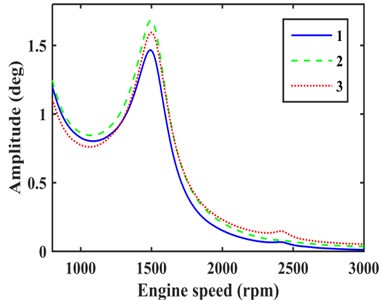
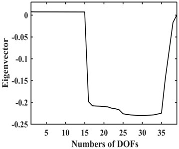
Fig. 3Third order mode shape of TVS
3. Optimization of matching of EC and TVD
3.1. Optimization mathematical model of EC and TVD
The torsional stiffness of EC and torsional stiffness and torsional damping coefficient of TVD were treated as design variables, the maximum torsional vibration torque of different segments should be less than the allowable torque was set as constrains, and the objective function was to minimize maximum TVEPE of TVS. The damping of rubber EC is internal damping that take damping coefficient Cr=ψ·Kr/2πω, where ψ is the loss coefficient, Kr is torsional stiffness of EC, and ω is the excitation frequency [21]. The optimization model is as follows:
F1=maxω=ω10≤t≤T1{∑38i=1512ki*[xi(t)-xi+1(t)]2+12k39*x39(t)2},
F2=maxω=ω20≤t≤T2{∑38i=1512ki*[xi(t)-xi+1(t)]2+12k39*x39(t)2},
Fm=maxω=ωm0≤t≤Tm{∑38i=1512ki*[xi(t)-xi+1(t)]2+12k39*x39(t)2},
s.t.G(z)≤0,
where, z is the design variable, ki is the torsional stiffness of different shaft segments after engine, xi(t) is the response of different DOFs, the corresponding frequency of engine speed from 800 rpm to 2000 rpm was divided into m-1 equal parts, ω1, ω2,…, ωm are an even number of equidistant points, Tm is the time period of TVS when ω=ωm, and crankshaft rotates two circles in one excitation period and 0.5th order excitation has the largest time period in multiple frequency excitation, so Tm=4π/0.5ωm, and G(z) is inequality constrains. The response of each harmonic exciting torque is added to determine the response of each DOF by linear superposition principle:
where, Xn is the amplitude column vector excited by the nth order harmonic torque, and x is the response column vector of the TVS, the corresponding steady-state solution is given by the imaginary part of Eq. (10).
3.2. Selection of installation position of EC and TVD
The inherent characteristics of TVS should be analyzed that the calculation is simplified by getting rid of the damping matrix and torque vector from Eq. (1), we have:
the third order natural frequency is 50.58 Hz by solving the characteristic equation which corresponds to the resonant speed of approximately 1500 rpm [22]. The corresponding mode shape is plotted in Fig. 3.
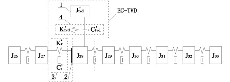
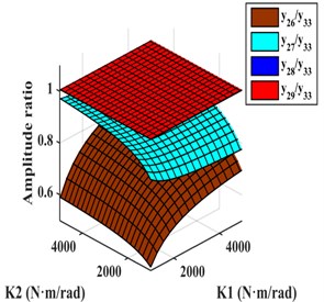
As shown in Fig. 3, the amplitudes of the DOFs which represent the driveshaft are larger in the vibration mode, so the damping device should be installed on the driveshaft to absorb more energy, and it is more appropriate to install EC and TVD at the front or back ends of the front half or rear half shafts needed for each case. The alternative installed position of EC as indicated by the dashed box in Fig. 4. The EC installed between J26 and J27, J27 and J28, J29 and J30, and J32 and J33 are represented by K1, K2, K3, and K4 respectively. TVD may be installed at any position close to J26, J28, J29, J33 or the front or back ends of EC. For instance, when EC is installed between J26 and J27, TVD may be installed at J26, J27, J28, J29 or J33. J26 is the inertia of front spline and universal joint, J27 is the inertia of front half shaft tube, J28 is the inertia of middle spline, and J29 is the inertia of middle universal joint. From J30 to J32, there are inertias of the rear half shaft tube, and J33 is the inertia of the rear universal joint.
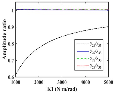
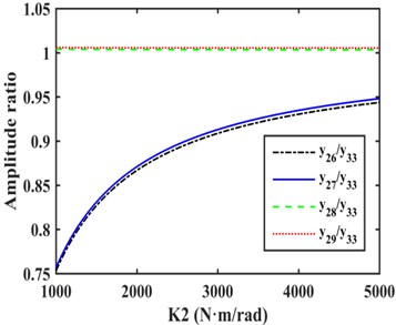
The relative amplitude ratios of J26, J27, J28, and J29 to J33that occurs when EC was installed between J26 and J27 are shown in Fig. 5(a). The amplitude of J26 was obviously smaller than J27, J28, J29, and J33, and J27, J28, and J29 were found to be basically equal, and all were slightly larger than the amplitude of J33, so TVD was installed on J27, J28, and J29, which can produce the same damping effect. Considering EC and TVD can be connected together into a EC-TVD coupling shock absorber that produces the effects of both its components.
Fig. 4Schematic diagram of installed position of four kinds of ECs

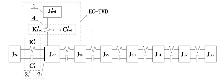
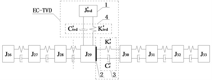
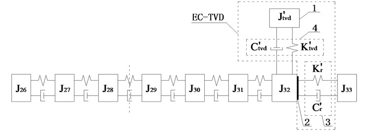
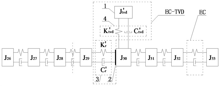
Its structure is depicted in Fig. 7. Body 1 is inertia ring connected to rubber 4 by vulcanization, body 2 is a lightweight hub connecting rubber 4 and EC 3, rubber 4 and EC 3 are not connected to each other because of the gap. To produce larger amplitude installation position and improve the damping effect, side A was connected to J27 and side B was connected to J26, as shown in Fig. 6(a), in which K'r and C'r are equivalent torsional stiffness and equivalent torsional damping coefficient of EC, and J'tvd, K'tvd, and C'tvd are inertia, torsional stiffness, and the torsional damping coefficient of TVD equivalent to the crankshaft.
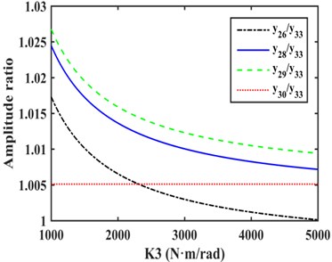
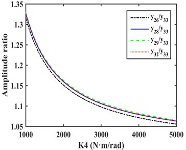
Fig. 5Amplitude ratios of different models
a)
b)
c)
d)
When EC was installed between J27 and J28, the relative amplitude ratios of J26, J27, J28, and J29 to J33 are as shown in Fig. 5(b). The amplitudes of J28, J29 and J33 were basically equal and larger than the amplitudes of other DOFs. As for EC-TVD, side A was connected to J28 and side B was connected to J27, as shown in Fig. 6(b).
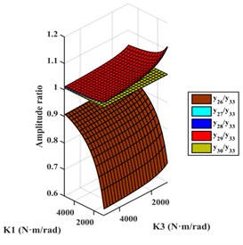
Fig. 5(c) shows that when EC was installed between J29 and J30, the amplitude of J29 was slightly greater than that of other DOFs, so side A was be connected to J29 and side B to J30, as shown in Fig. 6(c).
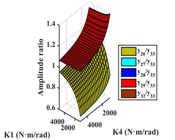
Fig. 5(d) shows that when EC was installed between J32 and J33, the amplitude of J33 was smaller than that of other DOFs, and the amplitudes of J26, J28, J29 and J32 were approximately equal, so side A was connected to J32 and side B to J33, as shown in Fig. 6(d).
3.3. Optimization and analysis of results
During optimization, the inertia of TVD are given fixed values for contrast analysis between different models, which reflects the effect of EC in the following text. Considering the actual situation, optimization range of EC was set from 1300 N·m/rad to 2500 N·m/rad, and the results of calculation are shown in Table 1, in which model e is a TVD installed on J32 without EC that optimized by energy method using Eq. (9), and the model f is an original model with no damping device. It can be concluded that model a has the most significant reduction on maximum TVEPE of TVS.
Fig. 6Schematic diagrams of installed position of EC-TVD
a)
b)
c)
d)
Fig. 7Schematic diagram of EC-TVD
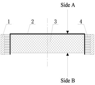
Fig. 8Comparison of amplitudes at the input end of rear axle with different models
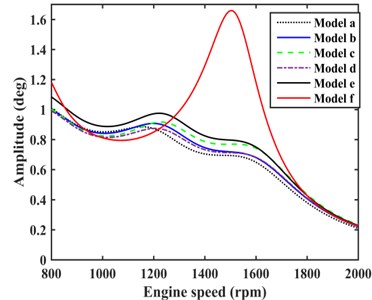
Table 1Results of optimization
Model | Stiffness of TVD (N·m/rad) | Damping coefficient of TVD (N·m·s/rad) | Stiffness of EC (N·m/rad) | Maximum TVEPE (J) |
a | 133.3011 | 0.1859 | 1300 | 0.0446 |
b | 139.5327 | 0.1903 | 1300 | 0.0524 |
c | 139.5475 | 0.1784 | 1300 | 0.0571 |
d | 137.8685 | 0.1815 | 1300 | 0.0542 |
e | 137.8190 | 0.1800 | 0.0584 | |
f | 0.2366 |
The damping effects of model a to model e were calculated, and the amplitudes of rear axle which have great influence on vehicle NVH performance were compared, as shown in Fig. 8. Model a showed the best damping effect, and the amplitude had a certain degree of reduction when engine speed varied from 800 rpm to 2000 rpm compared with model e. The damping effect of model b, c, and d were between model a and e.
4. Model improvement
To reduce torsional vibration of VPTS further, two ECs and a TVD were considered for use in the driveshaft. There were six schemes that four installation positions of EC can be installed in any combination of two ECs. The concrete schemes are as follows.
Scheme g: The two ECs were installed between J26 and J27 and between J27 and J28. TVD could be installed at J26, J27, J28, J29, or J33. The relative amplitude ratios of J26, J27, J28, and J29 to J33 are shown in Fig. 9(a). As shown the amplitudes of J28 and J29 were basically equal and larger than the amplitudes of other DOFs, so EC should be installed between J26 and J27. For EC-TVD, side A should be connected to J28 and side B to J27. The mechanical model of EC with EC-TVD as shown in Fig. 10(a).
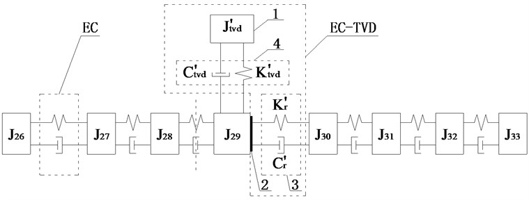
Scheme h: The two ECs were installed between J26 and J27, and between J29 and J30, TVD could be installed at J26, J27, J28, J29, J30, or J33. The relative amplitude ratios of J26, J27, J28, J29, and J30 to J33 are shown in Fig. 9(b). It shows the amplitude of J29 to be the largest, so EC should be installed between J26 and J27. For EC-TVD, side A should be connected to J29 and side B to J30. The mechanical model of EC with EC-TVD as shown in Fig. 10(b).
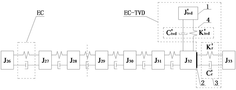
Scheme i: The two ECs were installed between J26 and J27 and between J32 and J33. TVD could be installed at J26, J27, J28, J29, J32, or J33. The relative amplitude ratios of J26, J27, J28, J29, and J32 to J33 are plotted in Fig. 9(c). It shows the amplitudes of J27, J28, J29, and J32 to be basically equal, and larger than the amplitudes of J26 and J33, so EC should be installed between J26 and J27. For EC-TVD, side A should be connected to J32 and side B to J33. The mechanical model of EC with EC-TVD as shown in Fig. 10(c).
Fig. 9Amplitude ratios of different models
a)
b)
c)
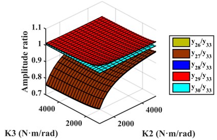
d)
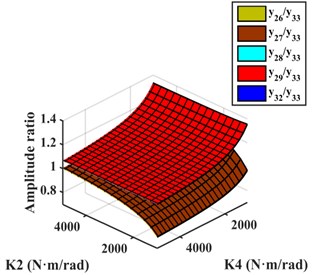
e)
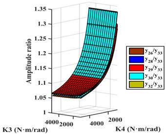
f)
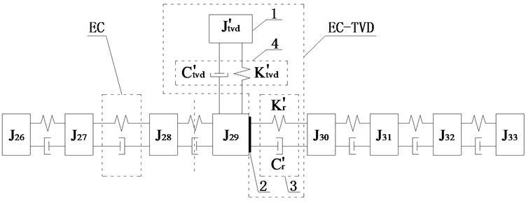
Scheme j: The two ECs were installed between J27 and J28 and between J29 and J30, TVD could be installed at J26, J27, J28, J29, J30 or J33. The relative amplitude ratios of J26, J27, J28, J29, and J30 to J33 are shown in Fig. 9(d). It shows the amplitude of J29 to be largest, so EC should be installed between J27 and J28. For EC-TVD, side A should be connected to J29 and side B to J30. The mechanical model of EC with EC-TVD as shown in Fig. 10(d).
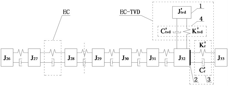
Scheme k: The two ECs are installed between J27 and J28 and between J32 and J33. TVD could be installed at J26, J27, J28, J29, J32, or J33. The relative amplitude ratios of J26, J27, J28, J29, and J32 to J33 are plotted in Fig. 9(e). It shows that the amplitudes of J28, J29, and J32 to be basically equal, and larger than the amplitudes of other DOFs, so EC should be installed between J27 and J28. For EC-TVD, side A should be connected to J32 and side B to J33. The mechanical model of EC with EC-TVD as shown in Fig. 10(e).
Fig. 10Schematic diagrams of installed position of EC and EC-TVD
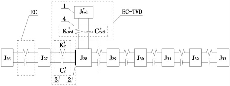
a)
b)
c)
d)
e)
f)
Scheme l: The two ECs are installed between J29 and J30 and between J32 and J33. TVD could be installed at J26, J28, J29, J30, J32, or J33. The relative amplitude ratios of J26, J28, J29, J30, and J32 to J33 is shown in Fig. 9(f). It shows the amplitude of J30 to be largest in the optimization range, so EC should be installed between J32 and J33. For EC-TVD, side A should be connected to J30 and side B to J29. The mechanical model of EC with EC-TVD as shown in Fig. 10(f).
At this time, the optimization variables were the torsional stiffness of two ECs and the torsional stiffness and torsional damping coefficient of TVD. The method described in section 3.1 was used and the results of calculation are shown in Table 2, it can be concluded that model i has the most significant reduction on maximum TVEPE of TVS. The amplitude of different models at the input end of rear axle are contrasted as shown in Fig. 11. It is obvious that model i has the best damping effect, and model j has the lowest damping effect.
Table 2Results of optimization
Model | Stiffness of TVD (N·m/rad) | Damping coefficient of TVD (N·m·s/rad) | Stiffness of front EC (N·m/rad) | Stiffness of rear EC (N·m/rad) | Maximum TVEPE (J) |
g | 134.0352 | 0.1985 | 1300 | 1300 | 0.0413 |
h | 136.2687 | 0.1858 | 1300 | 1300 | 0.0430 |
i | 134.5938 | 0.1872 | 1300 | 1300 | 0.0403 |
j | 142.0864 | 0.1913 | 1300 | 1300 | 0.0509 |
k | 141.4289 | 0.1829 | 1300 | 1300 | 0.0479 |
l | 142.0873 | 0.1787 | 1300 | 1300 | 0.0554 |
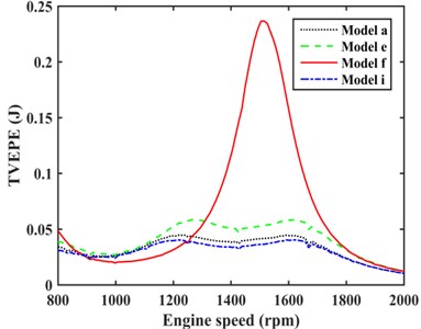
The damping effect of TVD model (model e), optimal model of one EC with TVD (model a), and optimal model of two ECs with TVD (model i) were compared as shown in Fig. 12. It can be concluded that model i had the better damping effect than model a. The suppression on maximum TVEPE of VPTS with model a, e, i, and f as shown in Fig. 13, it shows that model i has the more significant reduction on maximum TVEPE of TVS than model a and e.
Fig. 11Comparison of amplitudes at the input end of rear axle with different models
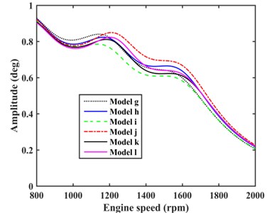
Fig. 12Comparison of amplitudes at the input end of rear axle with different models
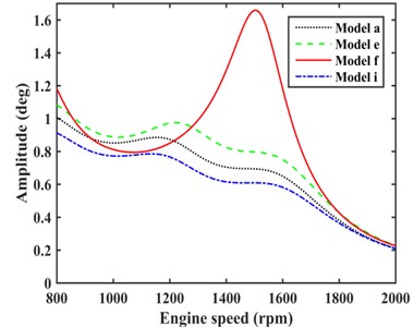
Fig. 13Comparison of TVEPE with different models
5. Conclusions
In view of the torsional vibration inherent characteristics of VPTS, this paper optimized position selection and parameter matching of EC and TVD by energy method. The main conclusions are as follows:
1) According to the resonant speed, every matching models of EC and TVD optimized by energy method can play a role in reducing torsional vibration. The choice of the installed position was found to have great influence on the amplitude of rear axle and the TVEPE. When one EC matches with TVD, model a has the best damping effect which better than model e; when two ECs matches with TVD, model i has the best damping effect which better than model a.
2) TVD can only reduce the amplitude near resonant speed, however, after reasonably matching with EC, the amplitude beyond resonant speed can also be reduced so as to improve the damping effect.
3) The self-made torsional vibration analysis optimization program was highly valuable during parameter optimization and matching of EC to TVD in the VPTS under practical condition.
References
-
Nestorides E. J. A Handbook on Torsional Vibration. Cambridge, 2011.
-
Wenbin Shangguan, Pan Xiaoyong Multi-mode and rubber-damped Torsional Vibration Absorbers for engine crankshaft systems. International Journal of Vehicle Design, Vol. 47, Issues 1-4, 2008, p. 176-188.
-
Londhe A., Yadav V. H. Design and Optimization of Crankshaft Torsional Vibration Damper for a 4-Cylinder 4-Stroke Engine. SAE Paper 2008-01-1213, Detroit, Michigan, USA, 2008.
-
Gawhade Ravikant, Ghare Prafulla, Satyanarayana V. V., et al. Effect of positions of front and rear masses in crankshaft design. SAE Paper 2011-28-0087, 2011.
-
Ebrahimi M., Jamil Z. M., Wood A. S. Optimum crankshaft damper selection. International Journal of Vehicle Noise and Vibration, Vol. 2, Issue 2, 2006, p. 111-124.
-
Mitianiec W., Buczek K. Interdependence of torsional vibration damper parameters on crankshaft's torsional vibrations. Journal of KONES Powertrain and Transport, Vol. 15, Issue 4, 2008, p. 351-358.
-
Homik W. Influence of temperature changes on torsional rigidity and damping coefficient of rubber torsional vibration damper. Transport Problems an International Scientific Journal, Vol. 6, Issue 1, 2011, p. 129-135.
-
Matyja T., Lazarz B. Selection of torsional vibration damper based on the results of simulation. Journal of Vibroengineering, Vol. 17, Issue 8, 2015, p. 4069-4077.
-
Takeo, Okamura Hideo, Sogabe Kiyoshi Experiments and analyses of the three-dimensional vibrations of the crankshaft and torsional damper in a four-cylinder in-line high speed engine. SAE Technical Paper No. 971996, 1997.
-
Iwanami K., Seto K. An optimum design method for the dual dynamic damper and its effectiveness. Bulletin of JSME, Vol. 27, Issue 231, 1984, p. 1965-1973.
-
Pennestri E. An application of Chebyshev’s min-max criterion to the optimal design of a damped dynamic vibration absorber. Journal of Sound and Vibration, Vol. 217, Issue 4, 1998, p. 757-765.
-
Liu Kefu, Coppola G. Optimal design of damped dynamic vibration absorber for damped primary system. Transactions of the Canadian Society for Mechanical Engineering, Vol. 34, Issue 1, 2010, p. 119-135.
-
Al-Hussain K. M. Dynamic stability of two rigid rotors connected by a flexible coupling with angular misalignment. Journal of Sound and Vibration, Vol. 266, 2002, p. 217-234.
-
Chaika V. Steady state response of a system of rotors with various types of flexible couplings. Journal of Sound and Vibration, Vol. 177, Issue 4, 1994, p. 521-537.
-
Franz Rößler D. I. The Geislinger steel spring coupling to lower torsional vibrations. ASME Internal Combustion Engine Division Spring Technical Conference, American Society of Mechanical Engineers, 2006, p. 517-523.
-
Hale L. C., Slocum A. H. Optimal design techniques for kinematic couplings. Precision Engineering, Vol. 25, Issue 2, 2001, p. 114-127.
-
Zhang B., Wan Y., Li Y., et al. Optimized design research on adjustable-speed permanent magnet coupling. IEEE International Conference on Industrial Technology, 2013, p. 380-385.
-
Dobre D., Simion I. Materials selection for improving the performance of flexible membranes from the structure of elastic couplings. Metalurgia International, Vol. 14, Issue 2, 2009, p. 21-25.
-
Bauchau O. A., Hodges D. H. Analysis of nonlinear multibody systems with elastic couplings. Multibody System Dynamics, Vol. 3, Issue 2, 1999, p. 163-188.
-
Thomsen S., Fuchs F. W. Design and analysis of a flatness-based control approach for speed control of drive systems with elastic couplings and uncertain loads. Proceedings of the 14th European Conference on Power Electronics and Applications, 2011, p. 1-10.
-
Mancuso Jon Coupling and Joints: Design, Selection and Application (2nd Edition). Marcell Dekker, New York, 1999.
-
Rao Singiresu S. Mechanical Vibrations (Fifth Edition). Prentice Hall, 2010.
About this article
Dr. Xiaodong Tan handled the work of writing the full manuscript. Dr. Lin Hua worked out a technology scheme of using torsional vibration damper to solve the problem of torsional vibration of the vehicle, and revised the manuscript at last. Dr. Chihua Lu put forward the main innovation point, and implemented parameters optimization by MATLAB programming. Dr. Can Yang established the torsional vibration model. Dr. Yongliang Wang plotted the plane graphics, and organized the optimization data, and created the tables.

