Abstract
The article presents our own research regarding reduction of the elevator cabin acoustic emission by the selection of an optimum method for the cabin construction stiffening. The elevator cabin structural panels with a width three times bigger than the standard one have been taken as a reference in the study. Numerical calculations have been performed. They constituted the basis for the methodology preparation as well as the method for the cabin panels stiffening. Measurements of the cabin panels acoustic emission as a result of determined impact have been used for optimization of the cabin construction increasing comfort while taking an elevator via the panels isolation with omega type stiffening elements.
1. Introduction
Thin-walled constructions made of sheet metal plates constitute a very wide industrial segment. The widest application of the thin-walled products can be noticed in automotive, boilers and elevators branches. Maintaining suitable stiffness of the construction together with sustaining appropriate strength and as low weight as possible constitute the subject of many research works prepared by development centers. Currently, alongside with thin-walled constructions the visual aspects of the products offered in the market are developed dynamically as well.
Authors of many research works touch the issues connected with elevating devices operation including vibrations while riding the elevator, the influence of wear and tear factors on the passengers comfort and permanent deformation causing damage and excluding a device from operation. In publication [1] the authors focus their attention on three numerical models of different solutions within overpresses in the central part of the elevator cabin side wall. Taking into account the elevator cabin passengers’ comfort, apart from a very important aspect raised by the authors in publication [2] which is the vibrations elimination coming from the elevator wheels and steering system, also the avoidance of “rumbling” phenomenon in the cabin coming from unstable cabin isolation due to e.g. unevenness of slides is of great importance. In the research works [2-4] the authors concentrate their attention on vibroisolation phenomena in reference to friction elevator cabins. In the publication [5] the author describes a phenomena connected with the issue and methodology of the cabin door power drive vibroisolation. Whereas, in the publication [6] the author focuses on the correctness of the elevator braking system operation including braking steadiness with minimization of deformations caused by irregular brakes operation. In the research work [7], the authors describe phenomena connected with autoparametric vibrations which can be used to control the elevator device. In the research work [8] the materials used as vibroisolators in the elevator cabin have been described. In the paper [6] the authors focus on the issue of noise abatement through the use of metal reinforcements. They do not concentrate, however, the issue of noise abatement through the use of vibration isolating mat and configuration connected.
While analyzing the literature review available in a wide spectrum of literature databases, a certain extent of insufficiency can be noticed in the shortage of publications describing how the cabins constructions behave due to different sources of vibrations present during the whole device operation.
2. Purpose of the research work
This compilation aims at demonstrating how the type of used stiffening influences the level of noise coming from the impact on the cabin panel on the test bench and how the level of noise changes depending on the change of a steel tester angle of falling on the panel. The results of the study it was decided to complete the panel with adhesive mats vibroisolating in the configuration of the mats themselves, or in combination with the applied mat stiffeners.
3. Characteristic of the research object
Thin-walled structural elements of the elevator cabin constituted the subject of the research study. The panels made of sheet metal plates – type 1.4301 and thickness 1.2 mm have been used as a reference for the research work. The panels with the width from 350 to 400 mm are used in standard cabins. For the research purpose the panels with 1150 mm width constituting the width three times bigger than the one of a standard panel have been prepared. Typical passenger elevator cabin is presented in Fig. 1.
The cabin presented in Fig. 1 consists of a roof (1), a back wall (2), side walls (3 and 4) and the floor (5). In the front part of the cabin (not presented in the drawing) there is an automatic door. The back and side walls presented in the drawing, in that case, are installed out of the panels with the width a way lower than 1150 mm. In such a case the influence of vibrations caused as a result of improper device operation will not be as much noticeable by a passenger as in case of a big uniform wall.
Fig. 1Drawing of a typical elevator cabin
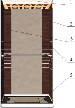
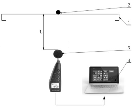
Fig. 2Scheme of the test bench: 1 – a measuring panel, 2 – a ball of a metal tester, 3 – CENTER 390 sonometer, 4 – a computer
4. Measurements methodology, plan of the research
With respect to the above, the executed research aimed at obtaining data to determine optimum method of the elevator cabin stiffening construction. Sound volume was recorded in the conditions of free falling of a metal ball hung on a rigid rod and impacting the most unfavourable place of the wall. The elevator cabin panels with 1150 mm width constituted the object of the applicable research work. To conduct the research the measuring system presented in Fig. 2 has been used.
CENTER 390 sonometer has been used to perform measurements. The sonometer characteristic has been presented in Table 1.
Table 1Characteristic of CENTER 390 sonometer
L.p. | Name | Range of value |
1 | Frequency range | 20 Hz-8 kHz |
2 | Level measurement range | 30-130 dB |
3 | Weighed curves | A / C |
4 | Microphone | Capacity |
5 | Averaging modes | Fast (125 ms) Slow (1 s) |
6 | Dynamics range | 100 dB |
7 | Accuracy | +/- 1,4 dB for conditions of 94 dB and 1 kHz |
8 | Functions | Over, under, max, min |
9 | Work temperature range | From 0 to 40 °C |
10 | Work humidity range | From 10 to 90 % |
11 | Device category | 2 acc.to IEC 61672-1 |
Measurements have been conducted in the test bench presented in Fig. 2 prepared for the purpose of launching to manufacture a suitable construction of the cabin walls.
The measurements were performed with the use of the research plan presented in Table 2.
Fig. 3Measurements test bench a) the back side of the wall b) the front side of the wall 1 – panel construction, 2 – sonometer, 3 – a metal impactor
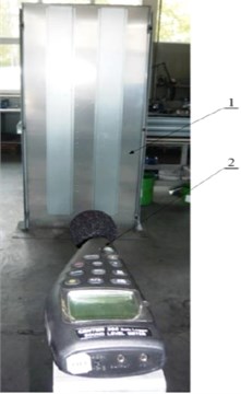
a)
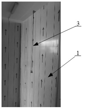
b)
Table 2Methodology of the cabin panel structure designation
Description of a panel structure | Panel weight [kg] | Designation | Measurement from α1=30 degrees angle | Measurement from α2=45 degrees angle |
Panel without stiffening | 22.2 | N/A | X | X |
Panel without stiffening, with two mats sound dampers | 22.6 | 2_m | X | X |
Panel with 2 narrow stiffenings | 28.8 | 2_w | X | X |
Panel with 3 narrow stiffenings | 33.1 | 3_w | X | X |
Panel with 4 narrow stiffenings | 35.5 | 4_w | X | X |
Panel with 1 wide stiffening | 28.4 | 1_s | X | X |
Panel with 2 wide stiffenings | 34.5 | 2_s | X | X |
Panel with 2 wide stiffenings, with two mats sound dampers | 35 | 2_s_2_m | X | X |
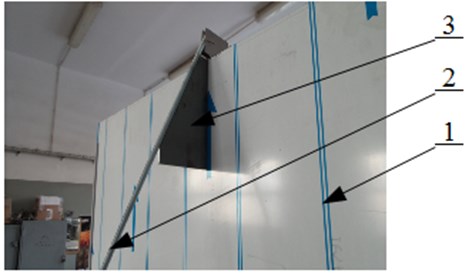
The measurements were performed with the assumption of a metal ball free falling. It was attached to a rigid rod (2), the initial position of which was determined in two α1= 30 and α2=45 degrees angle locations (3), what has been presented in Fig. 4.
Fig. 4Angle position of the rod with the metal ball
The measurements were conducted in accordance with the plan presented in Table 2, as per which 12 characteristics were supposed to be prepared, out of which each characteristic (e.g. α=30º for the panel 3_w) has been created by averaging the measurements obtained from 10 consecutive measuring tests of the ball falling on the panel surface executed one after the other. The average value was calculated as per the Eq. (1):
where: zi – the maximum value of the sound volume in the consecutive (i) measuring cycle of the ball free falling; k – the number of measurement cycles; i – the successive number of the ball free falling measurement.
Fig. 5Concept of the elevator cabin panels structure
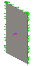
a) N/A
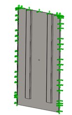
b) 2_w
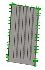
c) 3_w
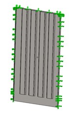
d) 4_w
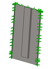
e) 1_s
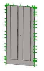
f) 2_s
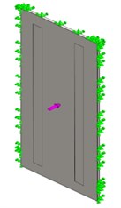
g) 2_m
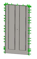
h) 2_s_2_m
To confirm the test assumptions, in the preliminary phase the numerical calculations of deflection of respective structural panels were performed on the basis of already compiled FEM – finite-element methods included in SolidWorks system.
5. Analysis of the research results
Model tests of the panels presented in Fig. 5 have been used to evaluate the compliance with requirements set by the standard [9] and architectural requirements included in valid standards.
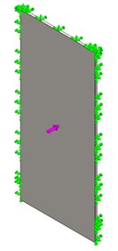
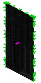
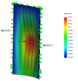
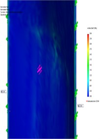
Fig. 6(a) presents the edge conditions, in which the panels were modelled by fixing them on three sides. The panel loading at the value of 300 N was applied in the most unfavourable position, in the middle of the panel, what causes the greatest deformation in that place. Fig. 6(b) illustrates an exemplary hardware model overlaid with a hexagonal grid, which has been analyzed by FEM, which has resulted in the graphical displacements occur as shown in Fig. 6(c) and stresses as shown in Fig. 6(d).
Fig. 6An example of numerical analysis: a) edge conditions, b) the imposition of the mesh, c) the values obtained displacement, d) generated stress values
a)
b)
c)
d)
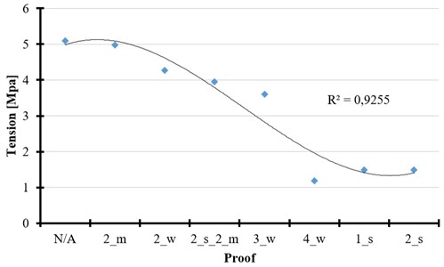
The results of stresses and dislocations calculations obtained via numerical calculations have been presented in the following Fig. 7 and Fig. 8.
Influence of different cabin panel constructions on the level of generated sound as a result of a metal ball free falling from different height has been illustrated in the subsequent Figs. 9-11.
Fig. 7Value of stresses appearing in the panel under 300 N loading
The edge conditions are presented in the Fig. 5 and Fig. 6. Those conditions were taken for numerical analysis purposes of the elevator cabin panels in different structural forms. Conducted numerical calculations were done on the basis of existing procedures included in Solid Works program. To compare the obtained results of stresses and dislocations in the panels, the attachment points in places corresponding to actual attachments of the panels in the cabin structure were used.
Fig. 8Values of dislocations obtained via numerical calculations under 300 N loading
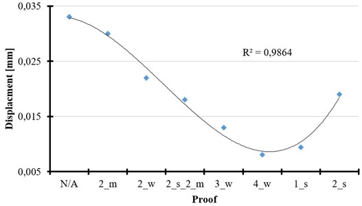
In each example, the panels were loaded with 300 N loading in accordance with the standard [9], which should be applied in the most unfavorable place on the surface of 5 cm2. In the Fig. 7 the stresses for all considered panels are presented. Together with the increasing number of stiffenings in the panel construction, the decrease of stresses value can be noticed. Inconsiderable increase of the stresses value can be seen exclusively for the wide stiffenings. The lowest value of stresses can be perceived for the panel construction with 4 narrow stiffenings.
Fig. 9Value of sound volume generated for 30 degrees angle of falling
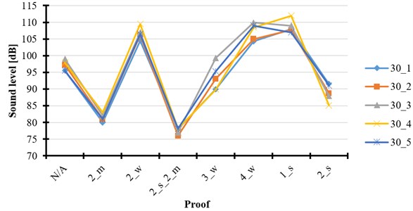
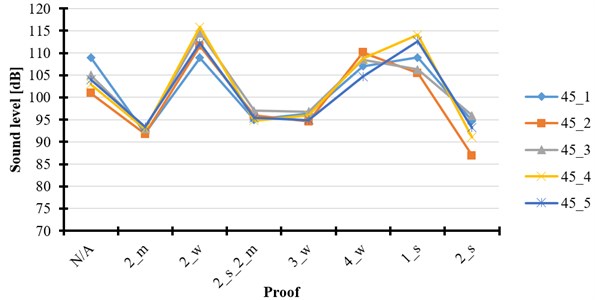
Fig. 10Geometrical values of the sound volume for 45 degrees angle of falling
Similar conclusions are raised upon the analysis of the chart presented in the Fig. 8 showing the value of dislocations appearing in the place where the loading was applied. The lowest dislocations can be noticed for the panel construction with 4 narrow stiffenings.
Figs. 9-11 show the results of measurements obtained in the test bench, the scheme of which is presented in Fig. 2. The results of measurements for five repetitions at the angle of ball falling – 30 degrees are illustrated in Fig. 9. In the particular case the distance between the ball and the panel surface is 500 mm in perpendicular line versus the panel surface. The route of the ball falling goes as per the curve drawn by attaching a rigid arm of L=1000 mm length at the top edge of the panel.
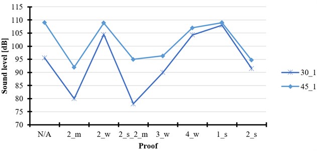
Fig. 11Sound volume value for 30 and 45 degrees angles
The results of measurements for five repetitions proper for the angle of ball falling – 45 degrees are illustrated in Fig. 10. In the particular case the distance between the ball and the panel surface is 700 mm in perpendicular line versus the panel surface whereas the route of the ball falling is analogous as for 30 degrees angle.
Comparison of the sound value generated for the ball free falling from two distances dependent on the metal rod deflection angle is illustrated in Fig. 11 (Fig. 4). Slight decrease of the sound value during the measurement at 30 degrees angle can be noted. It is caused by lower speed of the falling ball.
6. Conclusions
On the basis of carried out experimental research and numerical calculations it can be stated that:
1) Numerical calculations performed on the basis of assumptions referring to the panels structural changes confirm regularity of the assumptions in terms of the standard [10].
2) The lowest value of stresses at 300 N loading could be noticed for the panel reinforced with 4 stiffenings. The same influence of the number of stiffenings on the value of displacements could be observed in Fig. 8. It is the evidence for the proper operation of the panel with loading applied. However, the attention should be paid to the fact that time spent for the manufacture of such a panel is significantly longer than manufacture of the panel with one wide stiffening as well as the difference in received values of stresses and dislocations is as low that the production of four narrow stiffenings becomes uneconomical and pointless.
3) The influence of design changes of the cabin panels on the basis of conducted sound volume measurements confirms the justness of omega type stiffenings application. For the panels without stiffening (Fig. 5(a)) the value of generated sound is in a range of 95 to 100 dB for 30 degrees angle of falling. The sound value after the use of stiffenings has been reduced to a range of 85 to 90 dB what has significantly influenced the comfort of passengers riding the elevator. The same trend of the sound value drop can be observed for 45 degrees angle of falling – what has been presented in Figs. 9 and 10.
4) Elimination of the sound excitation in the cabin is a quite significant aspect influencing the passengers’ comfort.
5) The number of applied stiffenings does not always significantly reflect the improvement of strength parameters – the panel with one wide stiffening is of the strength comparable to the one with four narrow stiffenings but at 22 % lower weight what meaningfully influences the cost decrease and reduction of manufacture time due to the fact that a lower number of elements is to be joined.
6) Theoretical analysis within the influence of stiffening on the level of generated sound confirms that the height of the ball falling on the panel does not have any significant influence on the value of obtained measurements. It has been illustrated in Fig. 11.
7) Use mats soundproofing significantly reduces the generated sound intensity (average measured value of 81 dB for the 30st. And 92.6 for 45st.), Which, together with reinforcement of omega gave an additional significant decrease in sound level (respectively 77.4 dB and 95.6 dB).
8) The combination of omega reinforcements used in panel design with sound dampers mats glued to the wall of the cabin gives the best results in relation weight-stiffness/level generated volume.
9) Conducted numerical calculations and measurements of the sound value were used to implement new design solutions within so called wide cabin panels applied in passenger elevators.
References
-
Włodarczyk M., Józwik J., Adamowicz D. FEM numerical analysis of selected passenger elevators cabins side walls structural solutions. Science and Technology Development, Vol. 7, 2011, (in Polish).
-
Gardynski L., Lonkwic P. Testing polymer rollers memory in the context of passenger lift car comfort. Journal of Vibroengineering, Vol. 16, Issue 1, 2014, p. 225-230.
-
Burov A. A., Kosenko I. I., Troger H. On periodic motions of an orbital dumbbell-shaped body with a cabin-elevator. Mechanics of Solids, Vol. 47, Issue 3, 2012, p. 269-284.
-
Hirose M., Kobayashi T. Analyses and modeling of ultra-wideband on-body propagation channels depending on population density within an elevator cabin. IEICE Transactions on Fundamentals of Electronics Communications and Computer Sciences, Vol. E97A, Vol. 1, 2014, p. 94-100.
-
Lonkwic P. Regressive models of neural networks to identify acoustic signal of passenger elevator doors power plant. Rail Transport Technology, Vol. 10, 2013, (in Polish).
-
Lonkwic P., Szydło K., Longwic R., Maciąg P. Metoda ograniczania emisji hałasu emitowanego z wyrobów cienkościennych. Logistyka Vol. 6, 2014, p. 6818-6827.
-
Rijanto E., Muramatsu T., Tagawa Y. Control of elevator having parametric vibration using LPV control method: simulation study in the case of constant vertical velocity. IEEE Conference on Control Applications – Proceedings, Vol. 1, 1999, p. 527-532.
-
Shin B., Yoon S., Lee H., Koo Y. S., Jeong Y., Kang I. Mechanical properties and molecular structure of rubber materials with different hardnesses for vibration isolation of elevator cabins. Korean Journal of Metals and Materials, Vol. 51, Issue 10, 2013, p. 713-718.
-
PN EN 81.1 Safety Regulations Concerning Lift Structure and Installation, Part 1. Electric Lifts, 2012.
-
Lonkwic P., Szydło K. Selected parameters of the work of speed limiter line straining system in a frictional lift. Advances in Science and Technology, Vol. 8, Issue 21, 2014, p. 73-77.
-
Lonkwic P. Using disk spring solver application for prototyping disk spring in passenger lifts catchers. Applied Computer Science, Vol. 10, 2014, p. 67-74.
About this article
Special thanks and appreciation to NOVA TRADING Company from Toruń for the financial support owing to which it was possible to perform the research study and tests presented in the compilation.
