Abstract
A finite element model of a high-speed transportation was constructed, including its body in white (BIW), and traction system. And an analytical scheme on the interior structural radiation noise of a high-speed transportation was proposed under coupled multi-physical-field excitation. Rigid multi-body dynamics, boundary element method and large-eddy simulation were employed to extract secondary suspension forces, railway noise and surface pressure fluctuations, respectively, which were coupled with the structural modals to obtain the structural vibration response and noise. The experiment of vibration and noise for the high-speed transportation was conducted at speed of 350 km/h. A measuring point of vibration was randomly selected on the floor. The tendency and amplitude of its vibration velocity level and noise obtained from the experiment and simulation agreed well with each other, which validated the precision of numerical model and coupled multi-physical-field excitation.
1. Introduction
The high-speed transportation has gradually increasing coverage, which not only facilitates the travel of everyone but also produces noise problems meanwhile. As claimed by Shen [1], “the speed of a high-speed transportation is limited by nothing more than noise, and a vote is implementable for excessive noise pollution. The low-noise design of the high-speed transportation, in his view, is one of the most important elements. The interior noise of a high-speed transportation can be evaluated by the following two common methods including experiment and numerical simulation. And the former is more efficient, which can be directly used to measure noise at different speeds. However, lots of manpower and material resources are consumed, and its executable opportunity is very limited in this way. Such problem is well solved by the rapid development of the simulation technology.
At high speed, the main excitation sources of a high-speed transportation include the secondary suspension force of the bogie [2, 3], wheel-rail noise [4, 5] and aerodynamic noise [6].
At present, many researches on the simulation analysis regarding interior noise of the high-speed transportation have been conducted [7, 8]. The finite element model of BIW for a passenger transportation was established and the structural-acoustic coupling modal was calculated by Xie [9], and the unit simple harmonic load was applied on four fulcrums of the body longitudinally, vertically and laterally so as to solve the interior noise. Though its result could be used to analyze the transfer path between the mechanical force and BIW structural noise, its effect for the actual analysis of the interior noise was insignificant because the research object of the interior noise should include traction system. Xiao [10] established a dynamic simulation model of the high-speed transportation head-rail coupling model as well as finite element model and boundary element model of the body, and calculated the distribution and contribution of the passenger coach noise caused by the track irregularity. However, as track noise, aerodynamic noise and other main excitation sources were not considered, it could only be used to analyze the transfer path between the track irregularity excitation and interior noise. By means of the combination of the finite element method (FEM) and statistical energy analysis (SEA), Sapena [11] built a plate-beam simulation model of the driving cab and simulated the interior noise. The interior trim parts were regarded as the acoustic absorption coefficient, the coupling effect of mechanical excitation and aerodynamic noise excitation were considered, but the wheel-rail noise caused by the track irregularity was neglected.
Based on the previous researches, more complete boundary conditions in the driving process of a high-speed transportation were considered, the secondary suspension force of bogie, wheel-rail noise and aerodynamic noise were extracted by different methods, and the interior vibration and acoustic characteristics under three excitation and coupling effects were finally analyzed.
2. Acoustic theory of multi-physical-field coupling
Secondary suspension force was obtained by the multi-body dynamics of a high-speed transportation. In the generalized coordinates, the kinetic equation based on the Lagrange equation was as follows [12-15]:
wherein, ξ is the generalized coordinates of the structure, and “.” and “..” on its represent its first-order and second-order derivative for time; M is the structural mass matrix, and ”.” on it indicates its derivative for time; K is the generalized stiffness matrix; fg means the generalized mass force; D is the modal damping matrix; ψ represents the constraint equation; λ is the Lagrange multiplier; and Δ is the second-order derivative of the generalized coordinates for time.
The standard direct boundary element method (BEM) [16] was applied to obtain the wheel-rail noise caused by the track irregularity; and the aerodynamic noise was acquired through both the computational fluid dynamics and Lighthill acoustic analogy-based FW-H equation [17, 18].
Excitation sources could be extracted through the above theory. Then the interior vibration and acoustic response under multi-physical-field coupling effect were calculated by the indirect BEM. The coupled indirect boundary element model was consisted of two parts: Firstly, boundary element Ωs (with n1 nodes) coupled with the finite element model of the high-speed train was used to calculate the interior structural radiation noise. Secondly, boundary element Ω2 (with n2 nodes) uncoupled with the body was used to extract the excitation source. It was known the normal velocity vn0 on Ω2, then the monolayer potential on the whole indirect boundary element was σ= 0, and the structural dynamics equation of the double layer potential μ [19, 20] was as follows:
wherein: Ks, Cs and Ms are structural stiffness matrix, damping matrix and mass matrix, respectively; u represents the structural displacement vector; Fs indicates the external load acting on the structure (excluding the sound pressure load); Lcμ means the load acted by the sound pressure on the structure; and Lc is the coupling matrix.
3. Finite element model of the high-speed transportation
The finite element model of the high-speed transportation was mainly composed of BIW and drive system [21]. The material properties of all structures were basically same as that of the real transportation, which enhanced the accuracy of the calculation model.
Large-scale hollow aluminum extrusion profiles were applied in BIW of the high-speed transportation and welded into cylindrical structure, as shown in Fig. 1. Aluminum was slightly different in various regions. However, their density, elastic modulus and Poisson’s ratio were basically same, with the value of 2685 kg/m3, 72.4 GPa and 0.3, respectively. Finite element model and its cross-sectional structure were as shown in Fig. 2. And it was composed of 437,162 quadrilateral elements.
Fig. 1Geometric model of the high-speed transportation

Fig. 2Finite element model of body-in-white
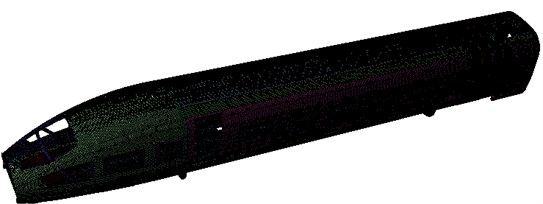
a) Finite element model of the high-speed transportation
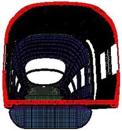
b) Section of the finite element model for the high-speed transportation
As shown from the relevant papers, the vibration frequency of the first order vertical bending of the high-speed transportation must be higher than 15 Hz [22]. Otherwise, serious resonance would occur in the operation process of the high-speed transportation, thus affecting the comfort and safety. Therefore, its modal frequencies were necessary to be tested by experiments. Four air springs were placed under the high-speed transportation to simulate a free state. Then an excitation was applied in the body to test its free mode, whose results were shown in Table 1. As seen from Table 1, the vibration frequency of the first order vertical bending of high-speed train was 18.79 Hz, higher than 15 Hz. Therefore, the above requirements can be satisfied by the designed high-speed train.
It was indicated from Fig. 2 that the high-speed transportation, in a very complex geometry, was very difficult to be ensured its reliability of follow-up results if its finite element model could not be verified by experiments. Therefore, the above-mentioned finite element model was applied to give the material properties and impose necessary connection constraints. Next, the first six free modes were computed numerically and compared with the experimental value, as shown in Table 2. It could be seen that the relative error of the experimental modal frequency and simulation value were controlled within 5 %, which was acceptable for such a large and complex geometry. In addition, the first six order vibration modes of the high-speed transportation were extracted as Fig. 3. It could be found that they were in consistency with the vibration model described in the experiment. Therefore, the finite element model of the high-speed transportation established in this paper was reliable and can be effectively used for subsequent numerical calculations of acoustics.
Fig. 3The modal shapes in the first 6 order

a) 16.31 Hz

b) 17.99 Hz

c) 22.98 Hz

d) 24.56 Hz

e) 25.66 Hz

f) 29.45 Hz
Interior trim parts were generally ignored and equivalent as an acoustical absorption coefficient in researches on the interior sound field of automobiles, aircrafts and other vehicles. The mass and volume of the traction drive system were in a relatively large proportion compared to the entire high-speed transportation. Therefore, it could not be substituted by some kind of equivalence relations. Bogie was majorly considered in the finite element model of traction drive system. The electrical equipment under the transportation was simplified as the uniform distributed mass and applied on corresponding nodes of the BIW model. The pantograph was not included in the motored coach studied in the paper. However, the power bogie was assembled as shown in Fig. 4, with such main components as connector of the body, frame, traction motor, wheel set, axle box, primary suspension, secondary suspension and damping systems.
Table 1The first 6 orders of the overall modals for the high-speed transportation
Order | Frequency / Hz | Vibrational modes |
1 | 15.71 | Body section diamonding |
2 | 18.79 | The first order vertical bending (whole vehicle) |
3 | 22.32 | The first order twisting |
4 | 23.98 | The first order vertical one (roof and underframe) |
5 | 26.02 | The first order twisting +horizontal bending |
6 | 28.12 | The second order vertical one (underframe) |
Table 2Comparisons between the experimental and the simulation modals
Order | Test modal / Hz | Simulation modal / Hz | Relative error / % |
1 | 15.71 | 16.31 | 3.8 |
2 | 18.79 | 17.99 | –4.3 |
3 | 22.32 | 22.98 | 2.9 |
4 | 23.98 | 24.56 | 2.4 |
5 | 26.02 | 25.66 | –1.4 |
6 | 28.12 | 29.45 | 4.7 |
Fig. 4Finite element model of the bogie
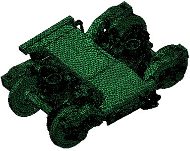
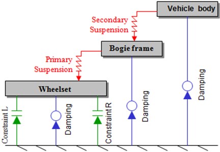
Fig. 5Connection diagram of the vehicle body structure
4. Extraction of multi-physical-field boundary condition
4.1. Secondary suspension force
As a complex multi-body system, the vehicle was divided into vehicle body, wheel-sets and bogies according to the elastic suspension system. The wheel-set was connected by means of the primary suspension system and bogie, and the bogie was connected by means of the secondary suspension and vehicle body, as shown in Fig. 5.
The commercial software SIMPACK was applied in the paper to simulate the operating conditions of the high-speed transportation. SIMPACK was featured with the major characteristic of supporting the sub-structure modeling and parametric modeling. The sub-structure modeling was to divide the system into several sub-structure systems, in order to simplify the workload, which avoided the complication of duplicate modeling for the similarly structural sub-systems or mirrored sub-systems. The parametric modeling was to define all places with same values in the model to have the same parameter. Therefore, if the model was necessary to be modified, it could be achieved through the simply modification of the parameter values, which could simplify the modeling process. The sub-structure modeling and parametric modeling were applied in the paper for the vehicle modeling.
In the multi-body dynamics model of the vehicle, the mass, rotational inertia and other properties of the vehicle body, frame and wheel-set were defined through body, whose parameter values were shown as Table 3. The connection method for the movements of all components was defined by the hinge and constraints. The suspension system was defined by the force components. During modeling the vehicle model, the vehicle system was usually divided into three parts: firstly, the sub-structure system of wheel-set and bogies; secondly, the sub-structure system of the vehicle body; thirdly the main model with virtual structure. Three parts were connected through a certain hinge and constraints to form a vehicle model as shown in Fig. 6.
Fig. 6Rigid multi-body dynamic model of the coach
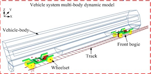
Table 3Rigid-body parameters of the coach
Body mass / t | Roll inertia / (t.m2) | Nod inertia / (t.m2) | Shaking inertia / (t.m2) | Height of gravity / m |
33.3 | 110 | 1636 | 1569 | 1.65 |
Longitudinal stiffness of steel spring / (kN.m-1) | Lateral stiffness of steel spring / (kN.m-1) | Vertical stiffness of steel spring / (kN.m-1) | Horizontal stiffness of air spring / (kN.m-1) | Vertical stiffness of air spring / (kN.m-1) |
920 | 920 | 886±60 | 125 | 195 |
Fig. 7Standard track spectrum

a) Vertical profile irregularity

b) Alignment irregularity
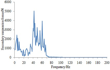
After obtaining the multi-body dynamics model of the high-speed transportation, the track spectrum shown in the Fig. 7 was applied in the model, the vertical secondary suspension force was obtained within the frequency band of 0 Hz-200 Hz at the speed of 350 km/h, as shown in Fig. 8.
As can be seen from Fig. 8, the secondary suspension forces were mainly concentrated in 25 Hz-75 Hz, whose peak was over 5000 N. Since the transportation was in uniform rectilinear motion, forces along the track and lateral force were thereby not considered in the paper.
Fig. 8Normal secondary suspension forces of the bogies
4.2. Track noise
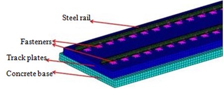
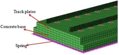
Track noise, including rolling noise, shock noise and curved whistling noise, was one of the main noise sources at high-speed operation [21]. In numerical analysis, the establishment of a rational and effective predictive model was a primary task in the research and control of track noise. The carry test studied in the paper was finished in the railway line. In reference to the structure of the slab track of this line, a finite element model was established, including steel rail, fasteners, track plates and concrete base, as shown in Fig. 9. The base beam beneath the foundation was equivalently treated through the grounding spring in subsequent computational model. Fasteners to fix rails were usually elastic strips, embedded iron base, insulated gauge blocks and rubber pads that had sufficient strength and durability and certain flexibility. In the modeling process, fasteners were simplified into a set of spring-damper unit to reflect their mechanical properties.
In the study of track noise, the track could be regarded as an infinitely long structure. Due to the effect of wheel-rail damping structures (such as fasteners), the vibration caused by the wheel-rail forces under the track effect cannot be transmitted for a long distance. In addition, the transmitted wave speed generated by the rail vibration was much larger than the running speed of the transportation. Therefore, the rail could be simplified into the stationary finite length structure in the prediction process of the wheel-rail noise. In accordance with the actual distance of transportation wheels, the wheel-rail force obtained by the calculation of the vehicle-track coupling dynamics model was applied on the rail surface in the manner of uniformly distributed load, as shown in Fig. 10.
Fig. 9Finite element model of the slab track
In the actual ballast-less track, the bottom of the finite element model was connected with the base beam. And the base beam was simulated in the application of ground spring to constrain the bottom of the base. In addition, its stiffness and damping were set to accurately simulate the ballast-fewer tracks, as shown in Fig. 11.
Fig. 10Application type of wheel-rail force
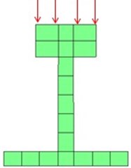
Fig. 11Model of ballast-less track
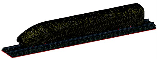
The structural radiation noise of the railway was excited by the wheel-rail force produced from the effects of wheels and the steel rail. The wheel-rail force was extracted by means of above multi-body dynamics. And the vertical wheel-rail force between the front wheel set of front bogie and railway at the speed of 350 km/h was selected as the example, whose frequency-domain result was shown in Fig. 12. The frequency-domain curves of left and right sides of each wheel set were basically same, and a larger magnitude (over 5 kN) was emerged in the vicinity of 10 Hz, which may be related to the resonance produced between the rigid body and standard track spectrum. Both the above wheel-rail FEM and the boundary element mesh of the high-speed transportation were imported to the Virtual.lab. Next, the coupling model was established as shown in Fig. 13.
Fig. 12Wheel-rail interaction force of a wheel set in the vertical direction
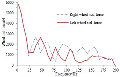
Fig. 13Calculation model of radiation noise for wheel-rail on the high-speed transportation surface
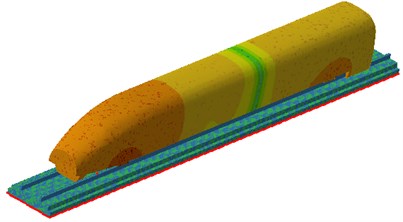
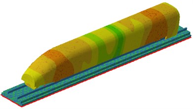
The acoustic power level of railway structure-borne noise under the effect of wheel-rail force was shown in Fig. 14. Greater railway structure-borne noise was appeared near 50 Hz, which could be mainly explained by two reasons. First, greater peak value of the wheel-rail force was appeared at 50 Hz, and second, the overall mode of the railway structure was found at 50 Hz. Therefore, under the coupling of them, larger noise was radiated by the railway. The sound pressure contours on the high-speed transportation surface under the wheel-rail force of 50 Hz and 130 Hz was extracted, as shown in Fig. 15. It can also be seen from the figure that the surface radiation noise of the high-speed transportation was maximal at the contact point of the wheel and track, which was consistent with the actual situation and thus indirectly indicated the reliability of the calculation results.
Fig. 14Sound power level of railway structure-borne noise
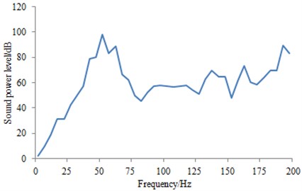
Fig. 15Sound pressure contours on the high-speed transportation surface under the wheel-rail force
a) 50 Hz
b) 130 Hz
4.3. Aerodynamic noise
When the speed was over 300 km/h, the aerodynamic noise became another major noise source of the high-speed transportation [21]. Therefore, the interior noise under the flow field excitation needed to be considered, namely wind noise. The aerodynamic noise of the high-speed transportation was mainly produced on uneven surfaces, such as near pantograph, bogies and other structures. Currently, aerodynamic noise source and its dissemination could not be simulated directly, especially for such a large model as transportations. DES method was applied in the paper to calculate the pressure pulsation acted by flow field on the body surface. Then in combination with the fluid-structure coupling technique, the coupling effect of pressure pulsation and body mode was analyzed. Finally, the vibration response and wind noise under the effect of the flow field was calculated.
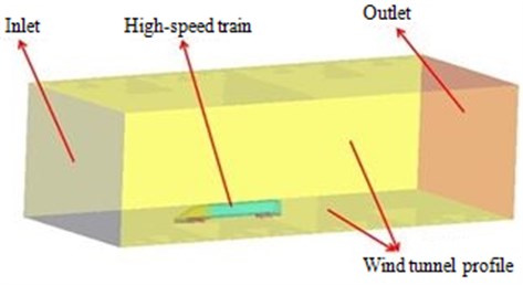
A train tunnel model was established to get the pressure pulsation, as shown in Fig. 16, including wind tunnel contour, air inlet, the studied train, and air outlet. The wind tunnel size and DES parameters were shown as Table.4. Under the premise of ensuring the surface pressure pulsation accuracy at the 0 Hz-200 Hz frequency band, units of the studied transportation surface were painted thinner and units of the head and end of the transportation surface was thicker in modeling to reduce the computation period substantially; the air flow field unit transferred from the body surface to the wind tunnel contour was distributed from densely to sparsely.
Table 4Dimension of the wind tunnel model and the parameters of LES
Wind tunnel contour / m3 | Distance between air inlet and the head of the train / m | Distance between the end of the train and air outlet / m | Distance between the top of the train and tunnel surface / m |
100×18×15 | 25 | 50 | 10 |
Wind speed of the air inlet / (km h-1) | Time step / s | Analytical frequency-domain / Hz | Number of time step |
350 | 0.0025 | 0-200 | 800 |
Fig. 16Wind tunnel model of the transportation for DES simulation
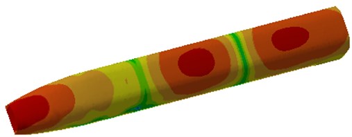
After the calculation, the fluctuating pressure on the body surface was extracted at 50 Hz, as shown in Fig. 17. It could be found that the pressure at the nose cone of its head was maximal. And with the increase of its distance from the nose cone, the pulsating pressure was decreased gradually, and turned into the negative value from the positive pressure value on the body surface of the sightseeing chamber. In addition, with the continuous increase of the distance, the pulsating pressure was gradually increased to be a positive value. Because the nose cone of the high-speed transportation was in the windward side, and when the curvature of the nose cone was transited to the body structure, the curvature change accelerated the gas flow speed, causing the negative pressure of some regions; what’s more, the change of the curvature structure of the transportation also resulted in dramatic changes of the fluctuating pressure on the transportation surface and great change of pressure gradient.
Fig. 17Calculation results of aerodynamic characteristics

The aerodynamic characteristic results in Fig. 17 were saved and imported into Virtual.lab software. The inner surface of the geometric model for the high-speed transportation was extracted and meshed to obtain the sound cavity model as shown in Fig. 18. In Fig. 18, it should be satisfied that the length of six elements was equal to one wavelength during meshing. Otherwise the calculation accuracy could not be met. Finally, there were 20871 elements and 23476 nodes in the sound cavity model. Similarly, Fig. 18 was also imported into Virtual.lab to conduct the pre-processing of acoustic mesh. Then, the tool in the software was applied to check the structural mesh and acoustic mesh, in order to remove the conflict between elements and node numbers. Finally, the aerodynamic characteristic results in Fig. 17 were mapped to Fig. 18, so that the aerodynamic characteristic results on the structural mesh could be obtained by the acoustic mesh. Finally, the vibro-acoustic coupling calculation was conducted to obtain the aerodynamic noise as shown in Fig. 19. It could be seen that locations with greater aerodynamic noise were mainly appeared in the vicinity of the nose and bogies due to certain airflow disorders generated by the sudden changes of the structure.
Fig. 18Interior sound cavity mesh model
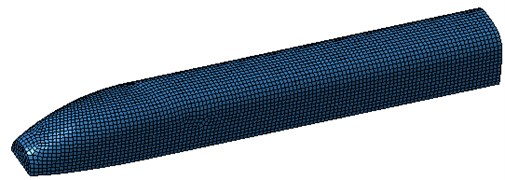
Fig. 19Calculation results of aerodynamic noise
5. Calculation results of multi-physical-field coupling
The wheel-rail coupling model was firstly built in Virtual.lab. Then, the calculation results of the aerodynamic characteristics were also imported into Virtual.lab. And the secondary suspension force in Section 4.1 was applied to the structural mesh of the aerodynamic model. Finally, the interior sound cavity mesh model was built in Virtual.lab. And through the application of the computational tools regarding multi-physics coupling in Virtual.lab software, the wheel-rail model, aerodynamic characteristics and secondary suspension forces were mapped to the interior sound cavity mesh. Finally, three excitations were obtained by the interior sound cavity mesh, and the calculated noise would be the result under the multi-physics coupling conditions.
The vibration velocity level was applied to evaluate the structural response of the measuring point, namely:
wherein: Lv represents the vibration velocity level; v expresses the vibration velocity of the body surface; and v0 is the reference speed of 5×10⁸ m/s.
Based on the mentioned multi-physics coupling model, the vibration velocity on the vehicle body floor was extracted as shown in Fig. 20. It could be seen many peak values and valley values in the vibration velocity curve. And the vibration velocity was especially minimal when the frequency was close to 150 Hz.
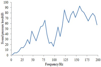
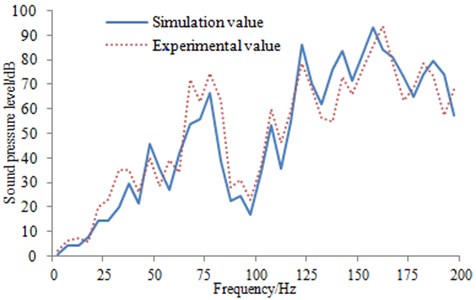
Subsequently, the interior center and structural radiation noise at 1.2 m away from the floor was acquired under the coupling effect of the secondary suspension force, railway noise and aerodynamic noise, as shown in Fig. 21. In the analytical frequency domain, the interior noise was presented an upward trend as a whole, and remarkably appeared a valley in the vicinity of 100 Hz.
Fig. 20Vibration velocity on the vehicle body floor
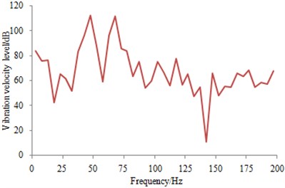
Fig. 21SPL at the coach interior center under the multi-physical-field coupled excitations
6. Experimental verification
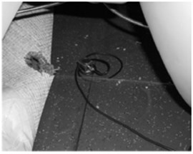
The high-speed transportation was a very complex structure, and therefore its numerical results should be necessarily verified. During the operation process of the high-speed transportation, a vibration acceleration sensor and microphone were mounted on the floor and middle position of the vehicle, respectively, in order to measure the vibration vehicle and interior noise, as shown in Fig. 22(a) and Fig. 22(b). The experimental equipment was shown as Fig. 22(c) and Fig. 22(d). The experimental process was shown in Fig. 23.
Multichannel data acquisition equipment was applied to collect signals from the vibration acceleration sensor and microphone. Then, the measured signal was imported into the computer for post-processing. Finally, the obtained vibration velocity and interior noise were compared with the simulation values, as shown in Fig. 24 and Fig. 25. It could be seen that a higher consistency was found in the curves of the simulated and measured vibration velocity levels from Fig. 24 and Fig. 25. Basically, most experimental peak values were captured in the simulation result, but some errors were appeared in individual frequencies. Overall, main excitations of the interior noise were considered in the paper due to very complex train structure and excitations. For such a complex engineering problems, this result was better.
Fig. 22Measurement points and equipment
a) Position of the acceleration sensor
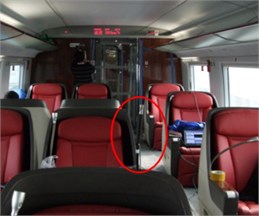
b) Position of the microphone
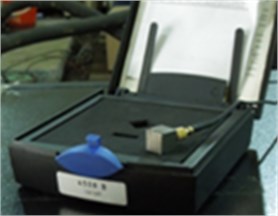
c) Acceleration sensor
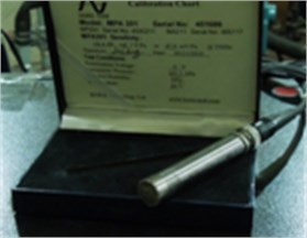
d) Microphone
Fig. 23Experimental process of the vibration velocity and interior noise
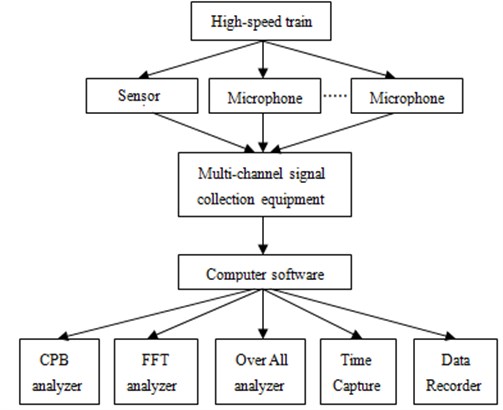
Fig. 24Comparison of vibration velocity levels between experiment and simulation
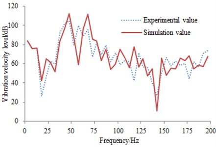
Fig. 25Comparison of sound pressure levels between experiment and simulation
7. Conclusions
1) The finite element model of a high-speed transportation with considering traction system was established, which could enhance the structural response accuracy of the body.
2) Rigid multi-body dynamics, boundary element method and large-eddy simulation were employed to extract different excitations including secondary suspension forces, railway noise and surface pressure fluctuations at speed of 350 km/h, respectively.
3) Based on the simulation model, the interior structural vibration and radiation noise were calculated under the effect of the coupled multi-physical-field excitation by means of coupled boundary element method.
4) The experimental vibration response and numerical calculation under coupled multi-physical-field excitation was completed. Measuring points of vibration and noise were randomly selected on the floor. And a higher consistency was found in the curves of the simulated and experimental results, thus ensuring the accuracy of the simulation model.
References
-
Shen Z. Y. Dynamic environment of high-speed train and its distinguished technology. Journal of the China Railway Society, Vol. 28, Issue 4, 2006, p. 1-5.
-
Gong D., Zhou J. S., Sun W. J. Coupled vibration analysis of flexible car body and bogie for high-speed train. Journal of Traffic and Transportation Engineering, Vol. 11, Issue 4, 2011, p. 41-47.
-
Jones C. J., Thompson D. J., Diehl R. J. The use of decay rates to analyze the performance of railway track in rolling noise generation. Journal of Sound and Vibration, Vol. 293, Issues 3-5, 2006, p. 485-495.
-
Li J. Q., He S. Q., Ming Z. An intelligent wireless sensor networks system with multiple server’s communication. International Journal of Distributed Sensor Networks, Vol. 7, 2015, p. 1-9.
-
Zhu Z., Xiao J., Li J. Q., et al. Global path planning of wheeled robots using multi-objective memetic algorithms. Integrated Computer-Aided Engineering, Vol. 22, Issue 4, 2015, p. 387-404.
-
Lin Q., Chen J. A novel micro-population immune multiobjective optimization algorithm. Computers and Operations Research, Vol. 40, Issue 6, 2013, p. 1590-1601.
-
Wong K. W., Lin Q., Chen J. Error detection in arithmetic coding with artificial markers. Computers and Mathematics with Applications, Vol. 62, Issue 1, 2011, p. 359-366.
-
Mellet C., Letourneaux F., Poisson F. High speed train noise emission: latest investigation of the aerodynamic/rolling noise contribution. Journal of Sound and Vibration, Vol. 293, Issues 3-5, 2006, p. 525-546.
-
Xie S. M., Fu Y. L., Wang Y. D. Acoustic property of structure-acoustic coupling system for rail car. Journal of Dalian Jiaotong University, Vol. 29, Issue 5, 2008, p. 40-44.
-
Xiao Y. G., Kang Z. C. Acoustic contribution analysis of passenger room of high-speed train under wheel-rail excitation. Journal of South China University of Technology: Natural Science Edition, Vol. 37, Issue 2, 2009, p. 98-101.
-
Sapena J., Tabbal A., Jove J. Interior noise prediction in high-speed rolling stock driver’s cab: Focus on structure-borne paths (mechanical and aero sources). Noise and Vibration Mitigation for Rail Transportation Systems, Vol. 118, Issue 1, 2012, p. 445-452.
-
Wei W., Xu Q., Wang L., et al. GI/Geom/1 queue based on communication model for mesh networks. International Journal of Communication Systems, Vol. 27, Issue 11, 2014, p. 3013-3029.
-
Brancati A., Aliabadi M. H. Boundary element simulations for local active noise control using an extended volume. Engineering Analysis with Boundary Elements, Vol. 36, Issue 2, 2012, p. 190-202.
-
Chen J., Lin Q., Shen L. L. An immune-inspired evolution strategy for constrained optimization problems. International Journal on Artificial Intelligence Tools, Vol. 20, Issue 3, 2011, p. 549-561.
-
Lin Q. Z., Zhu Q. L., Huang P. Z., Chen J. Y., Ming Z., Yu J. P. A novel hybrid multi-objective immune algorithm with adaptive differential evolution. Computers and Operations Research, Vol. 65, 2015, p. 95-111.
-
Tadamasa A., Zangeneh M. Numerical prediction of wind turbine noise. Renewable Energy, Vol. 36, Issue 7, 2011, p. 1902-1912.
-
Paiva B. J., Mendonca A. V. A coupled boundary element/differential equation method formulation for plate-beam interaction analysis. Engineering Analysis with Boundary Elements, Vol. 34, Issue 5, 2010, p. 456-462.
-
Wei W., Fan X., Song H., et al. Imperfect Information Dynamic Stackelberg game based resource allocation using hidden Markov for cloud computing. IEEE Transactions on Services Computing, 2016.
-
Pieringer A., Kropp W., Thompson D. J. Investigation of the dynamic contact filter effect in vertical wheel/rail interaction using a 2D and a 3D non-Hertzian contact model. Wear, Vol. 271, Issues 1-2, 2011, p. 328-338.
-
Chen J. Y., Lin Q. Z., Hu Q. B. Application of novel clonal algorithm in multiobjective optimization. International Journal of Information Technology and Decision Making, Vol. 9, Issue 2, 2010, p. 239-266.
-
Raghunathan R. S., Kim H. D., Setoguchi T. Aerodynamics of high-speed railway train. Progress in Aerospace Sciences, Vol. 38, Issues 6-7, 2002, p. 469-514.
-
Wei W., Yang X. L., Shen P. Y., et al. Holes detection in anisotropic sensornets: topological methods. International Journal of Distributed Sensor Networks, Vol. 21, Issue 9, 2012, p. 3216-3229.
Cited by
About this article
This project was supported by Fundamental Research Funds for the Central Universities; Research Innovation Project of Shanghai Municipal Education Commission; Science and Technology Guidance Project of Chinese Textile Industry Association.

