Abstract
In planetary gearbox, multiple gear pair meshing with each other and the vibration transmission paths from gear meshing points to the fixed sensors are time-varying. Therefore, fault diagnosis of the planetary gearbox is more difficult compared to that of fixed-axis gearbox, in which the vibration signal simulation models are very important. This paper constructs vibration signal models based on motion process modeling. This kind of modeling method is easier to understand compare with other methods which mainly based on the theory or physical laws behind the phenomena. The modeling process was presented in a step-by-step procedure according to the motion process of planetary gearbox. Frequency analysis was also implemented and comprehensive diagram was shown to help understand the result.
1. Introduction
Compared with fixed shaft gearboxes, planetary gears can provide a larger transmission ratio in a more compact package. However, a failure of gearbox may cause shutdown of the entire train and result in major economic losses. Therefore, the fault diagnosis of the planetary gearbox is crucial to prevent the mechanical system from malfunction.
Many techniques have been used in planetary gearbox fault diagnosis. Such as support vector machine (SVM) [1], wavelet packet transformation (WPT) [2], empirical mode decomposition (EMD) [3] and hidden Markov model (HMM) [4]. Anyway, in order to diagnose the failure of planetary gearbox more accurately, analyzing its operation mechanism and developing vibration signal simulation models is very important. August and Kasuba [5] studied the elastic mechanics theory of planetary gearbox in late 1980s. Kuang and Lin [6] developed the models of failure with considering the effect of meshing rigidity, damping and friction. However, the equations are too complex to understand. Choy [7] constructed a model of several kinds of fault types, but the final result is unsatisfactory.
This paper constructs vibration signal models based on motion process modeling. This kind of modeling method is easier to understand compare with other methods which mainly based on the theory or physical laws behind the phenomena.
The remaining sections of this paper are organized as follows. In Section 2, the vibration signal simulation model is developed, frequency analysis is implemented and comprehensive diagram is shown. The conclusions were drawn in Section 3.
2. Vibration signal simulation models
2.1. Only considering the planet-ring gear meshing process
The common planetary gearbox consists of sun gear, planet gears, ring gear, carrier etc., as Fig. 1 shows. This paper chooses the structure as an example to conduct vibration signal models. Firstly, two assumptions should be considered before modeling:
(1) The vibration signal only generated in planet-ring gear meshing process;
(2) Ignore the influence of different transmission paths; vibration signal is transmitted from meshing point to the sensor directly through the ring gear after generating, and the sensor is set up on the box which fixed with the ring gear.
Fig. 1Planetary gearbox and measurement arrangement
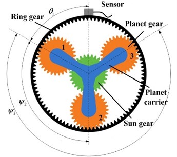
Then, the modeling process will be easy. Assume the vibration signal acquired by the sensor vri(t), i=1,2,...,N is generated by N planet gears meshing with ring gear. Due to the special structure, the relative phases between the vibration signals are different. The phase difference γri between vibration signals generated in the ith planet-ring meshing process vri(t) and the vibration signal generated in the first planet-ring meshing process vr1(t) can be calculated as follows:
where ψi is the relative angle between the position of the ith planet gear and the first planet (ψ1=0), as Fig. 1 shows. ZR is the teeth number of the ring gear.
So, there is a shifted equation between vri(t) and vr1(t) as follows:
where Tm=1/fm is the mesh period of the planetary gearbox.
As the gears rotates, the meshing points between planet gears and the ring gear moves. So, the distance between the source of vibration signal and the sensor varies. This will make the amplitude of the vibration signal varies. The process is called amplitude modulation. Since the planet gears are mounted on the planet carrier, the amplitude modulation effect repeats once per revolution of the planet carrier. Thus, the amplitude modulation function ari(t) is periodic with a fundamental frequency fC. Similar to vri(t) and vr1(t), there is a shifted equation between ari(t) and ar1(t) as follows:
where TC=1/fC is the rotate period of the planet carrier.
Thus, the amplitude-modulated vibration signals generated in the meshing process of the ith planet and ring gear can be expressed as follows:
The vibration signal generated in the meshing process of all planet gears with the ring gear occurs at the same time, so the sum of all signal acquired by the sensor can be expressed as:
Additionally, duo to the position of the first planet gear is uncertain, i.e. θ1 is uncertain, a new parameter t1=θ1/2πfC will be introduced to Eq. (5). Therefore, the vibration signal generated in the planet-ring gear meshing process can be expressed as:
Eq. (6) describes the vibration signal generated by planet-ring meshing process and acquire by a sensor mounted on the box.
2.2. Theoretical frequency analysis
As described above, the vibration signal model has been obtained. In order to analyze the health condition of the planetary gearbox, theoretical frequency analysis should be implemented. Fourier transform (FT) is the main tool of frequency analysis. Assume the system is linear, and then the FT of Eq. (6) is:
where F{⋅} represents the FT, * represents the convolution. It can be seen that Xr(f) is the sum of the convolution of N (I) and (II). And the (I) is considered at first. Due to ari(t) is periodic with a fundamental frequency fC, it can be decomposed by FT as follows:
where αrq, q∈Z is the Fourier coefficients of ar1(t). Additionally, according to the Eq. (3), the FT of (I) can be calculated as follows:
where the Function δ has the property that:
Then the (II) is considered. Similarly, vri(t) can be decomposed by FT as follows:
where βrk, k∈Z is the Fourier coefficients of vr1(t). And the FT of (II) can be calculated as follows:
Substituting the Eq. (1), (9) and (12) into Eq. (7):
=∑k∈Z∑q∈Z∑Ni=1αrqβrke-j2πqfC(t1+ψiTC2π)e-j2πkfmγriTmδ(f-kfm-qfC)
=∑k∈Z∑q∈Z∑Ni=1αrqβrke-j2πqfCt1e-j(kZR+q)ψiδ(f-kfm-qfC).
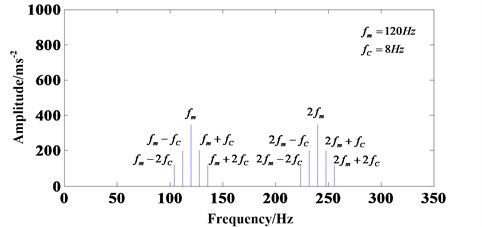
The δ(f-kfm-qfC) implies that Xr(f)≠0 only when f=kfm+qfC and k,q∈Z. Namely, only considering the planet-ring gear meshing process, qfC will be existent as sidebands around kfm. Fig. 2 shows this phenomenon very well.
Fig. 2Frequency spectrum diagram with only considering planet-ring gear meshing process
2.3. Effect of the sun-planet gear meshing process
The vibration signal vsi(t)i=1,2,...,N generated in the sun-planet gear meshing process is considered in this section. Similarly, two assumptions are made before modeling:
(1) The vibration signal generated in planet-ring gear and sun-planet gear meshing;
(2) Ignore the influence of different transmission paths; vibration signal is transmitted from meshing point to the sensor directly through the ring gear after generating, and the sensor is set up on the box which fixed with the ring gear.
According to the different transmission distances, two amplitude modulation functions ari(t) and asi(t) are used for vibration signal vri(t) and vsi(t), respectively. And they are both periodic with a fundamental period TC=1/fC. However, due to the signal transmission distance of sun-planet ring meshing process is longer than the signal transmission distance of planet-ring gear meshing process, so |asi(t)|<|ari(t)|.
It is also need to be considered that the relative phases between all vibration signalvsi(t). Similar to vri(t), the phase difference γsi between vibration signals generated in the ith sun-planet meshing process vsi(t) and the vibration signal generated in the first sun-planet meshing process vs1(t) can be calculated as follows:
where ZS is the teeth number of the sun gear.
It can be demonstrated that γsi=γri [8]. In addition, due to a planet gear meshes with sun gear and ring gear at the same time but the distances to the sensor of the vibration signal generated in the two meshing processes are different, so there is a phase difference γsr between vsi(t) and vri(t). Thus, there is a shifted equation between vsi(t) and vs1(t) as follows:
And there is a shifted equation between asi(t) and as1(t):
Duo to the position of the first planet gear is uncertain; the vibration signal generated in the sun-planet gear meshing process can be expressed as:
Therefore, considering both planet-ring bot sun-planet gear meshing process, the synthetical vibration signal xr,s(t) can be expressed as:
=∑Ni=1ar1(t-t1-ψiTC2π)vr1(t-γriTm)
+∑Ni=1as1(t-t1-ψiTC2π)vs1(t-(γri+γsr)Tm).
For the purpose of frequency analysis, FT of Eq. (18) is calculated as follows:
=∑k∈Z∑q∈Z∑Ni=1[αrqβrk+αsqβske-j2πkγsr]e-j2πqfCt1e-j(kZR+q)ψiδ(f-kfm-qfC),
where αsq, βsk are the Fourier coefficients of as1(t) and vs1(t), respectively.
Fig. 3Frequency spectrum diagram with considering planet-ring and planet-sun gear meshing process
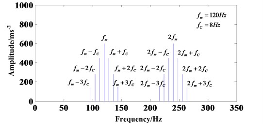
The δ(f-kfm-qfC) implies that Xr(f)≠0 only when f=kfm+qfC and k,q∈Z. Fig. 3 can explain the result loudly. Without considering the transfer path effect, only considering the sun-planet and planet-ring gear meshing process, qfC will be existent as sidebands around kfm. However, the amplitude of the signal will be higher than before through the contrast of Eq. (13) and (19).
3. Conclusions
Vibration signal simulation model for planetary gearbox was developed based on motion process modeling. The model considered both planet-ring and sun-planet gears meshing processes. The modeling process was presented in a step-by-step procedure according to the motion process of planetary gearbox. Then, frequency analysis was also implemented and comprehensive diagram was shown to help understand the result.
The shortage of this paper is the vibration signal models of fault gears are not constructed and the effect of transmission path is not considered. These will be the research contents that need to be studied more thoroughly.
References
-
Baccarini L. M. R., Silva V. V. R., et al. SVM practical industrial application for mechanical faults diagnostic. Expert Systems with Applications, Vol. 38, Issue 6, 2011, p. 6980-6984.
-
Fan X. F., Zuo M. J. Gearbox fault detection using Hilbert and wavelet packet transform. Mechanical Systems and Signal Processing, Vol. 20, Issue 4, 2006, p. 966-982.
-
Ricci R., Pennacchi P. Diagnostics of gear faults based on EMD and automatic selection of intrinsic mode functions. Mechanical Systems and Signal Processing, Vol. 25, Issue 3, 2011, p. 821-838.
-
Kang J. S., Zhang X. H. Application of hidden Markov models in machine fault diagnosis. Information – an International Interdispilinary Journal, Vol. 15, Issue 12B, 2012, p. 5829-5838.
-
August A., Kasuba R. Torsional vibration and dynamic loads in a basic planetary gear system. Journal of Acoustics, Stress, and Reliability in Design, Transaction of the ASME, Vol. 108, 1986, p. 348-353.
-
Kuang J. H., Lin A. D. The effect of tooth wears on the vibration spectrum of a spur gear pair. Journal of Vibration and Acoustics, Vol. 123, 2001, p. 311-317.
-
Choy F. K., Polysckchuk V., Zakrajsek J. J., et al. Analysis of the effects of surface pitting and wear on the vibration of a gear transmission system. Tribology International, Vol. 29, Issue 1, 1996, p. 77-83.
-
Parker R. G., Lin J. Mesh phasing relationship in planetary and epicyclical gears. Journal of Mechanical Design, Vol. 124, 2004, p. 365-370.
About this article
