Abstract
This paper reviews the research progress of soft substrate interlayer film, including the applications and the preparation methods of the soft substrate interlayer film, the testing means of the films’ structure and composition and the researches of the film damage, especially the dynamic damage. As well as the future research directions and applications are put forward.
1. Introduction
With the development of science and technology, the scope of film application expands gradually and the film material has become one of hot research fields now. Flexible films [1-4] get rapid development, which have the advantages of the light weight, convenient transportation and folding and bending performance. The mechanical properties of flexible film can affect electrical, optical, mechanical and magnetic properties of the functional components. Thus flexible film can be applied to the hard coating, film transistor and flexible electronics (such as the flexible electronic display, thin-film solar panel, electronic skin, artificial muscle, etc.).
In the actual application process, the films work in a complicated environment. The external load or thermal load will cause the film to produce crack, buckling and other structural changes, which affects the service life of the films. In order to extend the service life and enhance the mechanical properties of the film, substrate interlayer film soft (SSIF) structure is gradually into people's horizons. The flexible film with transition layer is similar to the multilayer film’s structure, which can effectively improve the mechanical strength and the mechanical strength of the film-substrate system. The transition layer can combine the advantages of two different properties of thin film and reduce the impact of the mismatch and improve the mechanical strength of the film substrate system [5-8].
In this paper, we will mainly focus on the structure of soft substrate interlayer film and the damage under dynamic and static loads.
2. The film damage under static load
In the practical application, the main failure modes of film are fracture, buckling and delamination. When the film is subjected to tensile stress, the fracture and interface crack can be produced. Similarly, the buckling and debonding are caused by compressive stress. The researches of film damage are introduced in the following.
2.1. The crack damage of the film
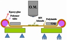
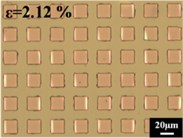
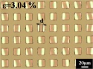
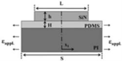
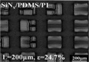
At present, the relevant researches about the mechanical properties of the transition film are still based on the experiments and finite element analysis [9-11]. Sun’s studies had found that the organic transition film has a significant effect to improve the tensile properties of the inorganic film system [12-14]. SiNx was deposited by plasma enhanced chemical vapor deposition on the polyimide (PI) substrate. The observation and loading apparatus of the whole experiment process were shown in Fig. 1(a). The results of SiNx film under different tensile loading conditions were shown in Fig. 1(b), (c). In order to improve the service life of the thin film, the researchers modified the structure of the film, adding a PMDS interlayer film into the film. The structure of the soft substrate interlayer film was shown in Fig. 2(a). The Schematic of the SiNx/PDMS films’ cracks under tensile stress was shown in Fig. 2(b).
Fig. 1An array of SiNx islands on a PI substrate stretched in uniaxial tension. a) Schematic of the in-situ tensile test system under an optical microscope; b) and c) Micrographs of SiNx subjected to different strain
a)
b)
c)
Fig. 2a) The structure of the soft substrate interlayer film; b) The schematic of the SiNx/PDMS films’ cracks under tensile stress
a)
b)
It was found that the additional PDMS film made the critical strain of the SiNx film increase. At the same time, the research group also found that after adding the transition PDMS film, the size of the SiNx film island will affect the mode of crack (i.e. interface cracks and tunnel cracks).The energy release rate of SiNx-PI membrane system is derived:
where E*=E/(1-ν2), L is the length of the film island and 2a is the length of debonding film. σre is a residual stress and εappl is the strain applied to the substrate.
2.2. Interfacial damage of flexible film
At present, scholars researched the crack on the interface of flexible film. Some scholars have proposed the theory method of calculating the maximum stress for the interfacial fracture problem of the flexible film [15-17].
Lu et al. [18] analyzed the buckling behavior of crack propagation, established the model by the method of perturbation and calculated the energy release rate of the deformed and the corresponding interface crack. In the film substrate system, the expansion of the interfacial crack occurred after the film delamination buckling, the expression of the energy release rate is:
where M is the moment of the layered edge, E is the modulus of elasticity, t is the thickness of the film and ΔN is the change of the force.
Using the perturbation method, the normalized control equation is established as:
where is the deflection of thin films, is the critical load and is the stiffness of the film. Using boundary conditions, both the value of deflection and the energy release rate can be calculated.
2.3. Buckling damage of thin films
The buckling of thin films is divided into the debonding buckling and non-debonding buckling. The main forms of the debonding buckling are linear buckling, circular buckling, and telephone linear buckling. In order to describe the buckling phenomenon, the buckling of thin films is studied by experiments and numerical simulations. The researches on the theory of the film are still in the exploration [19-21]. On the elastic substrate, the buckling of films caused by compressive stress has been observed [22-24], and the sketch of buckling is shown in Fig. 3.
Fig. 3Optical microscopy images of surface patterns formed in the film under compressive stress
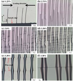
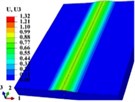
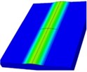
Fig. 4Evolution of crack formation across a buckle. a) Formation of an equi-width buckle in the first step; b) crack propagation from the buckle; c) crack-induced further delamination
a) 1.25 % compressive strain
b) 2.78 % compressive state
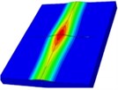
c) 2.94 compressive state
Wang, et al. [22-24] observed the buckling of metal films on the PMMA substrate under compressive stress. Buckling deformation was calculated by digital image correlation method. The residual stress formed by different materials and ratios in the film and substrate system may cause various instability modes. When the film and substrate structure is subjected to a uniaxial compressive load, the critical stress of buckling is:
where is elasticity modulus of the film, is poisson ratio of the film, is the height of buckling and is the width of the film. At the same time, they found that the transverse crack of the film would appear when the compression load increased. The crack-induced further delamination caused by the compression load was simulated using the finite element method, shown in the Fig. 4.
3. Damage behavior of thin films under dynamic loading
At the present stage, the theory of the damage of the film under the static load can be said to have been mature. But the film specimens work in complex noise environment and random disturbance including mechanical, thermal, etc. Therefore, the dynamic buckling of films should be also analyzed [25-27].
Bouzakis, et al. [28] obtained the young's modulus of the film by nano indentation technique. At the same time, they had an experiment that the ball fallen to impact the surface of the film, and then got the impact-time curve, as shown in Fig. 5. After repeated impact of the small ball, the contact ring on the surface of the film became larger and larger and kept in a stable size finally.
It is not complete to analyze the effect of the load on the film substrate system by the experiment, so we should have theoretical analysis. It is the fact that the internal stress wave is generated in the system of film and substrate under dynamic load. Stress wave propagates in the system of film and substrate, which will eventually lead to the buckling of the film. This theoretical model can refer to the study of the buckling behavior of a single plate subjected to impact loading. Petry, et al. [29] used dynamic load amplification factor to study the dynamic stability of a simple supported plate with a defect under the impact load. The influence of the impact function, the size of the defect and the geometric size of the plate on the buckling of the plate was studied. By combining the plane strain model, the equilibrium equations were obtained.
where is the deflection of thin films. Based on the boundary conditions, the equation of the buckling displacement of the surface was obtained.
Li, et al. [30] studied the system of film and substrate under dynamic load by experiments, theory and finite element simulation. The organic glass (PMMA) was used as the substrate and the metal Ti was prepared by sputtering deposition. The films with different thickness were impacted by drop weight loading device. Using the force sensor and displacement sensor, force-displacement curve was obtained. The photos of the film surface after the impact were shown in Fig. 6.
Fig. 5The device of the ball impacting to the film and the results of the experiment
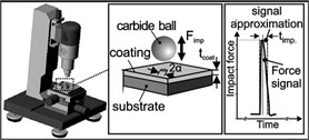
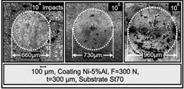
Fig. 6The surface morphology of the film: a) the bottom surface of the impacted specimen, b) the top of the impacted specimen

The Tiersten model [31] was used to analyze the impact of the structure of film and substrate. They assumed that substrate was in accordance with plane motion control differential equation:
The boundary conditions of the Tiersten model were used in the contact interface:
After Laplace transform and inverse transform, the results were obtained:
Because of the complex solution, the numerical method wan used to analyze solution. The Crump method was used to solve the numerical Laplace inverse transformation and the fast Fourier transform was used to solve the Fourier inverse transformation. After transformation, the final results were obtained. The numerical solution of displacement and stress can be solved by using the Laplace inverse transform and the fast Fourier inverse transform of MATLAB.
4. Conclusion
Flexible film containing transition layer is in development. There are still many theoretical problems and technical issues need to be studied and resolved. The researches of the damage behavior and critical parameters and the damage evolution of soft substrate interlayer film under tensile and compressive loading are not mature. It is difficult to design and applicate the film. A complete theoretical system has not been formed for the film under dynamic loading.
Further understanding and characterization of the deformation and damage mechanism of the film with transition layer are more useful in practice to improve the design of the transition film components. The studies of mechanism and the researches on the reduction and prevention of damage in the process of service are important for the application of these products.
References
-
Cordill M. J. Flexible film systems: current understanding and future prospects. JOM, Vol. 62, Issue 6, 2010, p. 9-14.
-
Mo A. K., Brown V. L., Rugg B. K., et al. Understanding the mechanism of solvent-mediated adhesion of vacuum deposited Au and Pt thin films onto PMMA substrates. Advanced Functional Materials, Vol. 23, Issue 11, 2013, p. 1431-1439.
-
Lupo D., Clemens W., Breitung S., et al. OE-A Roadmap for Organic and Printed Electronics. Applications of Organic and Printed Electronics. Springer, US, 2013, p. 1-26.
-
Zhu H. J., Yan Q., Zhu X. D. Progress on the flexible thin film solar cells. Materials Review, Vol. 26, Issue 9, 2012, p. 138-141.
-
Deng J., Yan G., et al. Effects of nitrogen flowrates on properties of TiSiN coatings deposited by arc ion plating combining with medium-frequency magnetron sputtering. International Journal of Refractory Metals and Hard Materials, Vol. 42, 2014, p. 108-115.
-
Deng J., Li S., Xing Y., et al. Studies on thermal shock resistance of TiN and TiAlN coatings under pulsed laser irradiation. Surface Engineering, Vol. 30, Issue 3, 2014, p. 195-203.
-
Xing Y., Deng J., Li S., et al. Cutting performance and wear characteristics of Al2O3/TiC ceramic cutting tools with WS2/Zr soft-coatings and nano-textures in dry cutting. Wear, Vol. 318, Issue 1, 2014, p. 12-26.
-
Ma F., Zhao T., et al. A novel method to prepare ZnO/Ni multilayer thin film used in back electrode for solar cell. Solar Energy Materials and Solar Cells, Vol. 137, 2015, p. 73-78.
-
Long R., Dunn M. L. Channel cracks in atomic-layer and molecular-layer deposited multilayer thin film coatings. Journal of Applied Physics, Vol. 115, Issue 23, 2014, p. 233514.
-
Miller D. C., Foster R. R., Zhang Y., et al. The mechanical robustness of atomic-layer-and molecular-layer-deposited coatings on polymer substrates. Journal of Applied Physics, Vol. 105, Issue 9, 2009, p. 093527.
-
Marx V. M., Toth F., et al. The influence of a brittle Cr interlayer on the deformation behavior of thin Cu films on flexible substrates: Experiment and Model. Acta Materialia, Vol. 89, 2015, p. 278-289.
-
Sun J. Y., Lu N., Yoon J., et al. Inorganic islands on a highly stretchable polyimide substrate. Journal of Materials Research, Vol. 24, Issue 11, 2009, p. 3338-3342.
-
Sun J. Y., Lu N., Oh K. H., et al. Islands stretch test for measuring the interfacial fracture energy between a hard film and a soft substrate. Journal of Applied Physics, Vol. 113, Issue 22, 2013, p. 223702.
-
Sun J. Y., Lu N., Yoon J., et al. Debonding and fracture of ceramic islands on polymer substrates. Journal of Applied Physics, Vol. 111, Issue 1, 2012, p. 013517.
-
Zhang G. P., Li Y. P., Zhu S. F. Deformation and fracture behavior of several metallic multilayers and mechanisms. Journal of Nanjing University, Vol. 45, Issue 2, 2009, p. 180-186.
-
Zhang J. Y., Liu G., Sun J. Size effects on deformation and fracture behavior of nanostructured metallic multilayers. Acta Metallurgica Sinica, Vol. 50, Issue 2, 2014, p. 169-182.
-
Yang J. S., Wang F. Ductility of polymer-supported metal films with curved interface. Journal of Solid Mechanics, Vol. 32, Issue 1, 2011, p. 1-9.
-
Wang T. Asymptotic solutions for buckling delamination induced crack propagation in the thin film-compliant substrate system. Theoretical and Applied Mechanics Letters, Vol. 4, Issue 4, 2014, p. 041003.
-
Feng X., Yang B. D., Liu Y., et al. Stretchable ferroelectric nanoribbons with wavy configurations on elastomeric substrates. ACS Nano, Vol. 5, Issue 4, 2011, p. 3326-3332.
-
Hutchinson J. W. The role of nonlinear substrate elasticity in the wrinkling of thin films. Philosophical Transactions of the Royal Society A: Mathematical, Physical and Engineering Sciences, Vol. 371, Issue 1993, 2013.
-
Yang Q. S., Wang X. F. Numerical studies on buckling process of tensioned plane membrane. Journal of Beijing Jiaotong University, Vol. 37, Issue 4, 2013, p. 114-118.
-
Wang S. B., Fang Y. Z., Jia H. K., et al. A new application of digital image processing to investigate thin compressed films: the measurement of buckling propagation. Optics and Lasers in Engineering, Vol. 48, Issue 11, 2010, p. 1140-1144.
-
Xue X. L., Wang S. B., Jia H. K., et al. Experimental investigation on buckling of thin films in mechanical-thermal coupled-field. Physics Procedia, Vol. 19, 2011, p. 158-163.
-
Xue X. L., Wang S. B., Zeng C. F., et al. Buckling-delamination and cracking of thin titanium films under compression: Experimental and numerical studies. Surface and Coatings Technology, Vol. 244, 2014, p. 151-157.
-
Knotek O., Bosserhoff B., Schrey A., et al. A new technique for testing the impact load of thin films: the coating impact test. Surface and Coatings Technology, Vol. 54, 1992, p. 102-107.
-
Chandra B. P., Chandra V. K., Mahobia S. K., et al. Real-time mechanoluminescence sensing of the amplitude and duration of impact stress. Sensors and Actuators A: Physical, Vol. 173, Issue 1, 2012, p. 9-16.
-
Parnell W. J., Martin P. A. Multiple scattering of flexural waves by random configurations of inclusions in thin plates. Wave Motion, Vol. 48, Issue 2, 2011, p. 161-175.
-
Bouzakis K. D., Lontos A., Vidakis N., et al. Determination of creep behaviour of monolayer thick plasma sprayed coatings, by means of the impact test and an analytical FEM supported evaluation procedure. Thin Solid Films, Vol. 377, 2000, p. 373-381.
-
Petry D., Fahlbusch G. Dynamic buckling of thin isotropic plates subjected to in-plane impact. Thin-Walled Structures, Vol. 38, Issue 3, 2000, p. 267-283.
-
Li P., Lin An Li, et al. Experimental research on buckling of nano-thin film under impact load. Applied Mechanics and Materials, Vol. 130, 2012, p. 1262-1265.
-
Tiersten H. F. Elastic surface waves guided by thin films. Journal of Applied Physics, Vol. 40, Issue 2, 1969, p. 770-789.
About this article
Financial support from the National Natural Science Foundation of China (Grant No. 11572218) is greatly acknowledged.
