Abstract
The paper presents advanced computational models suitable for the development of a modern powertrain in the field of noise and vibration. The aim is to decide how detailed the model should be to correctly describe the vibrational and acoustic performance of the powertrain. In general, the advanced computational model of the powertrain – a virtual powertrain – is developed as a powerful tool for the solution of structural and also thermal and fatigue problems. Main results from the field of vibrations are verified by technical experiments using laser vibration technique and strain gauges. Afterwards, the simpler computational models are compared with the virtual powertrain and the results are discussed. The virtual powertrain is assembled, as well as numerically solved, in Multi Body System extended by user written subroutines. The virtual engine results are validated by measurements performed on compression ignition in-line six-cylinder engine.
1. Introduction
Forced by legislation and consumers’ demands, vehicle manufacturers have achieved considerable reductions in internal and external noise in recent decades. The key to understand such advances and to focus on future efforts is recognition of the contributions of various noise sources and their dependence on operating conditions. The powertrain (engine, clutch, gearbox, drive shaft and differential) is the primary source of noise and vibration under certain conditions, and is considered in this paper into some detail. The origins of powertrain related dynamic forces are examined and design principles are discussed, to minimizing them both at source and in transmission to the vehicle.
In today’s fast paced automotive market, the computational methods are prerequisites to ensure low levels of sound, vibration and harshness (NVH) of modern powertrains. The complexity of computational models is always very important issue. The paper will present new and advanced approaches for evaluation of different powertrain noise sources and their influence on vibrations transmitted to the interior or exterior of the car.
2. Review of state of the art
Historically, there have been numerous different attempts to simulate powertrain NVH performance. Technical literature includes a large number of different computational models, the references [1-4] are examples of a wide variety of the computational models used in powertrain NVH. The present state of the art in powertrain simulations presents computational models solved in time domain using Multibody systems (MBS) with high share of flexible bodies, often based on Finite Element Method (FEM) principles. Some powertrain components, e.g. flywheels, pins or pulleys, are included only as an additional mass, or frequently they are not included at all. Crankshaft and engine block interactions are often solved using a hydrodynamic or more advanced elastohydrodynamic model of a slide bearing. However, full elastohydrodynamic solution of Reynolds equation, including shell and pin deformations, is still not fully adopted for powertrain dynamics with many slide bearings.
Gear interactions are other key noise sources of most powertrains. There are many more or less advanced computational models in technical literature describing the gearbox in different conditions. For example, Yongxiang [5] shows efficient methodology for abnormal noise control of automobile transmission in the neutral idle condition s NVH simulations. The single gear interactions are also presented in [6-8].
A torsional vibration damper is an important component of specific cranktrains. Fundamentally, it can significantly decrease noise and vibrations. Present state of the art of computational modelling of rubber or viscous torsional dampers is included in systems of torsional springs and dampers in some kind of an arrangement. These computational models correctly describe damper frequency behaviour for a solution in time domain. The rubber damper can, sometimes, influence the axial crankshaft vibrations, therefore, axial properties have to be sometimes also incorporated.
Valvetrain computational models have been being developed during a long period of time as well. First, discrete computational models of the valvetrain (still in use) have included discrete point masses or springs. Springs have included only linear dependences of force vs. deformation. A tappet or a valve has been excited by a lift function. With increasing MBS the valvetrain computational models became more complex and incorporated rigid bodies and nonlinear contact forces. Later, some of the parts were replaced by spring-damper-mass bodies or beam bodies. Camshaft angular irregularities on the basis of a separate cranktrain model solution have been also incorporated. The present state of the art includes computational models with flexible parts. Spring models use flexible bodies with valve coil contacts enabling to understand contacts between coils, as well as, spring stiffness changes [9]. The single valvetrain models are assembled to a complete valvetrain model [10]. However, drive timing mechanism or injection pump influences are not included often, and neither are influences of a compressor, an oil pump or other powertrain accessories.
Heretofore, each sybsystem of a powertrain has been solved separately. It has, sometimes, been extended by influences of other model results or measurement results but these results have been obtained from separate solutions. Valvetrain dynamic simulations can be taken as an example. A camshaft is driven by an angular velocity obtained from a separate cranktrain solution, or from measurements. Nowadays, the need to solve all powertrain parts together continuously increases. This solution enables to include all interactions among parts. The results will show that, for example, valvetrain dynamics is highly influenced by a cranktrain but at the same time the cranktrain is slightly influenced by the valvetrain, both influenced by a timing drive or an injection pump.
3. Aim of the work
This work evaluates noise sources in a powertrain and presents ways how the dominant noise source can be reduced by advanced computational models.
The considered features of the computational models can be summarized as follows:
Elastic deformations of main components enabling an evaluation of outer surface vibrations.
Interactions between engine subsystems (cranktrain, valvetrain, gear timing drive etc.).
Steady state or transient solution.
Non-linear behaviour of interactions between components (slide bearings, gear tooth contacts, cam tappet contacts, etc.)
All the numerical approaches presented are integrated into a commercial program ADAMS extended by FORTRAN subroutines written by the authors. Proposed methods are applied to a turbocharged compression ignition (CI) six-cylinder engine.
4. Advanced computational model for vibration solution
4.1. Flexible parts
Flexible bodies represented by FE (Finite Element) models have crucial importance for powertrain dynamics simulations. The proposed computational model uses reduced form of FE flexible bodies and the Craig-Bampton method is used [10] for reduction of the FE models.
Crankshaft and engine block FE models present the fundamental components. The other flexible parts using reduced FE models are a camshaft, valve springs and rockers.
4.2. Torsional rubber damper model
A rubber damper MBS model includes only general properties like torsional and axial stiffness with dependency on frequency and temperature. The frequency dependency in time domain is modelled via a series of four Maxwell members (spring and damper). The overall static stiffness values originate from a detailed solution of the three dimensional FE model. Parameters of Maxwell members are fitted by Matlab software functions to satisfy frequency dependency of the rubber. More details can be found in [11].
4.3. Slide bearing model incorporating pin tilting influences
The loading capacity of a slide bearing included in the model is considered in a radial direction and including pin tiltings, which means that radial forces and moments are included in the solution. The slide bearing forces are based on a numerical solution of Reynolds differential Eq. (1), including elastic deformations of shells. The hydrodynamic forces are stored in hydrodynamic databases. Basic form of Reynolds equation is:
where p is pressure in oil film, h is oil film thickness, U is relative velocity of pin relative to shell, ρ is oil density, η is oil viscosity, x and z are coordinates and t is time.
The Reynolds equation is transformed into dimensionless coordinates, discretised by Finite Difference Method (FDM) and then numerically solved by Gauss-Seidel method employing Successive Over Relaxation (SOR) strategy. The pressure in oil film is integrated and the resulting forces are stored in reaction force databases. During the solution in time domain MBS solver reads the forces from databases for every solution time step.
4.4. Gear timing drive
A model of a gear meshing includes variable stiffness of meshing with backlash option. The variable stiffness of meshing gears enables to incorporate tooth meshing frequency, as well as its harmonic components. The computational model of meshing helical gear also includes all resultant forces between teeth (radial, axial and tangential forces).
The variable meshing stiffness is found by solution of a nonlinear contact FE model of the meshing gears. The resultant variable stiffness is inserted into the MBS computational model of meshing helical gears and into the gear timing drive computational model, respectively.
If the meshing gear stiffness can be found, for example, the meshing gear damping cannot be accurately calculated, therefore, a different approach for a damping determination has to be chosen. Reduced inertia moment IRED for both meshing gears (I1 and I2) is calculated as:
Together with an average value of gear meshing stiffness kTavg, this reduced inertia moment produces a natural frequency:
The angular damping of meshing gear can be then determined as:
where ξR is relative damping of meshing gears. The value of the relative damping can be selected from a range between 0.01 and 0.3. The value of 0.3 is selected for this work because it has already been validated by many projects dealing with meshing gear analyses.
The meshing helical gears transfer time dependent torques and causes also axial FAi and radial FRi forces. These forces can be determined from equations:
where Mzi is a time dependent torque of a meshing helical gear, Ri is a pitch radius of the gear, αR is pressure angle of gears and βR is helical gear angle.
4.5. Fuel injection pump
When taking into consideration the powertrain NVH, the injection pump can highly influence the dynamics of powertrain parts. In particular, the valvetrain and the gear timing drive can be influenced by high peak torques of the injection pump.
Essentially, the used type of injection pump includes injection pistons. The movement of the injection piston is controlled by a cam profile. Each cam interacts with a roller tappet. This interaction (cam – roller contact) produces time dependent torques on a pump shaft in each pump section. Fig. 1 shows time dependent torques acting on the injection pump shaft in dependence on a crank angle.
Fig. 1Injection pump torque vs. crank angle for engine speed n= 2200 min-1
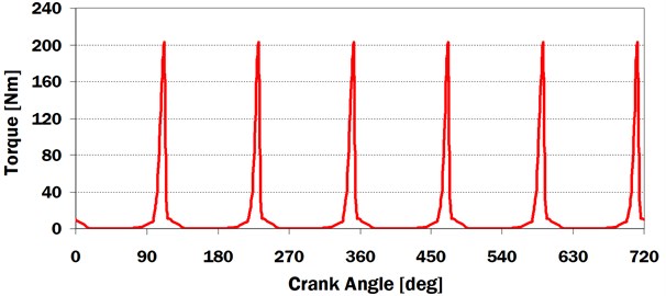
Influences on the other powertrain components are the main aims of an injection pump MBS model. Therefore, the model includes a rigid body with inertia moment corresponding to a shaft and reduced inertia moments of other pump parts. Resultant torque in dependence on time and corrected for engine speeds is entered into the rigid body.
4.6. Virtual powertrain
An advanced computational model of the powertrain, i.e. a Virtual Powertrain, is solved in time domain. This enables to incorporate different physical problems, including various nonlinearities. The Virtual Powertrain is assembled, as well as, numerically solved in MBS ADAMS. ADAMS is a general code and enables an integration of user-defined models directly using ADAMS commands or using user written FORTRAN or C++ subroutines.
The virtual powertrain includes all significant components necessary for NVH analyses. The included modules are a cranktrain, a valvetrain, a gear timing drive with fuel injection pump and a rubber damper.
5. Validation of virtual powertrain results
In general, powertrain surface vibrations and radiated noise are coupled. The noise produced by a powertrain can be taken from crankcase surface velocities. Fig. 2 shows measured and calculated Campbell diagrams of crankcase surface velocities near the second cylinder and crankshaft axis. The value 5×10⁻⁸ ms-1 is used as a reference velocity. Measured results have been determined by POLYTEC Vibrometer OFV-5000.
Fig. 2Measured and calculated Campbell diagrams of crankcase surface velocities near the second cylinder and crankshaft axis
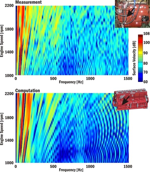
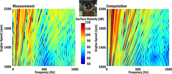
The main area of the most significant velocity amplitudes is from 50-350 Hz. The first and second torsional frequencies (210 Hz and 255 Hz) can be found in computed, as well as, in measured results. Engine attachments to the ground have fundamental influence on surface velocities with frequencies up to 150 Hz. The computed and measured results show the movement of the whole engine (a rotation about a crankshaft axis direction) at natural frequency 66 Hz. The Campbell diagrams (Fig. 3) shows measured and calculated Campbell diagrams of crankshaft pulley surface velocities in crankshaft axis.
Fig. 3Measured and calculated Campbell diagrams of crankshaft pulley surface velocities in crankshaft axis
6. Computational model influences
6.1. Cranktrain computational model
Cranktrain computational models of different levels can be used for cranktrain dynamic solutions. Until now, the cranktrain dynamics has been solved using an independent cranktrain model with or without flexible bodies. Flexible bodies have been mostly reduced FE models. The following cranktrain computational models are used for comparisons:
A powertrain model including a cranktrain, a valvetrain, a timing gear mechanism and an injection pump. Main components are modelled as flexible structures incorporating reduced FE models (a crankshaft, an engine block, a camshaft, rockers and valve springs).
An independent cranktrain model incorporating reduced FE models of a crankshaft and an engine block.
An independent cranktrain model with a rigid engine block model incorporating reduced FE model of a crankshaft.
Independent cranktrain models include the crankshaft with an additional body located in a crankshaft front end. An axis inertia moment of the additional body is equivalent to axis inertia moments of meshing timing gears and the camshaft. The cranktrain computational models are presented in Fig. 4.
The solution times needed to complete computational model solutions can be very important. Table 1 presents values of solution times for different computational models solving the cranktrain dynamics including the solution of 50 engine cycles.
Table 1Solution times needed to complete model solution for different computational models
Model | Powertrain model | Cranktrain model | Cranktrain model with rigid engine block |
Solution time [min] | 153 | 61 | 4 |
Intel XEON 4 GHz Quad-core CPU and 64 GB RAM personal computer with Windows 7 64-bit operating system has been used for computational model solutions.
Reduced FE models, in particular, significantly increase solution times needed for computational model solutions. A large number of contacts between valvetrain parts also increase solution times.
Important results of cranktrain computational models are torsional vibrations of the crankshaft. Fig. 5 compares results of the chosen cranktrain computational models and measurements (without a torsional damper). Only the chosen harmonic orders resonating in the speed range of target engine are presented.
Fig. 4Cranktrain computational models
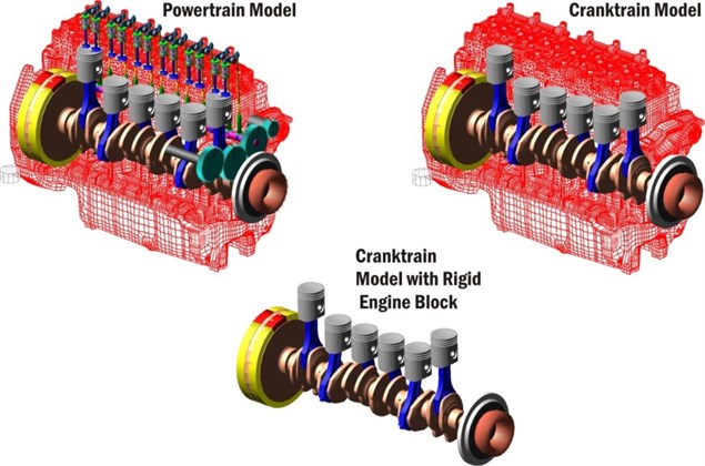
Fig. 5Harmonic order analyses of crankshaft pulley torsional vibrations without torsional damper for different computational models
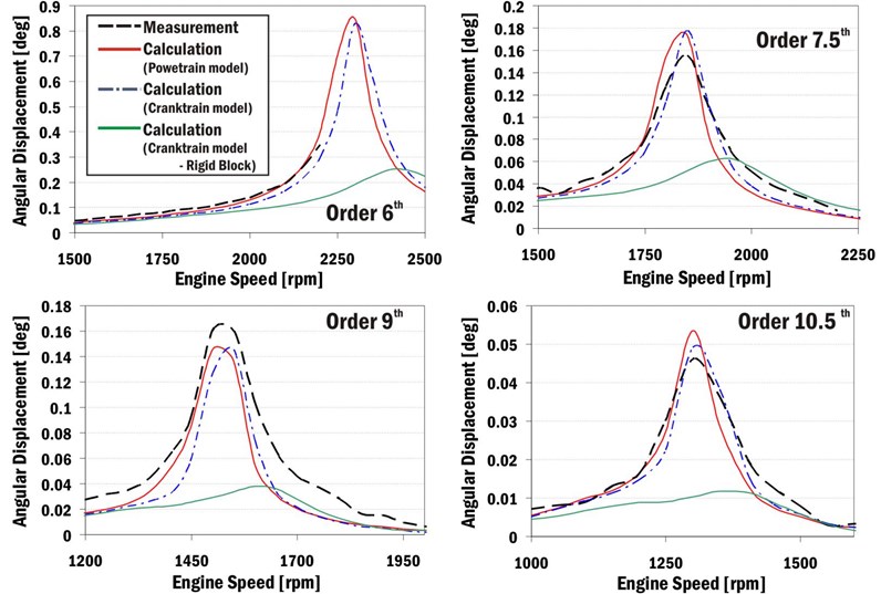
The powertrain model and the independent cranktrain model incorporating reduced FE models of a crankshaft and an engine block quite closely match the measurements. Graphical representations are influenced by high engine speed steps for measurements and computations. The independent cranktrain model with a rigid engine block model gives inaccurate results and cannot be recommended for cranktrain dynamic solutions in the case of the target engine.
Cranktrain model types also influence computed normal velocities on engine block surfaces. The normal velocities of the engine block surface significantly influence the acoustic emissions produced by a powertrain. Fig. 6 presents Campbell diagrams of a normal velocity of a crankcase surface near the first cylinder and a crankshaft axis. Fig. 7 presents Campbell diagram of a normal velocity of the bottom engine cover (an oil sump) surface near the second cylinder. A value 5×10⁻⁸ ms-1 is taken as a reference velocity for Campbell diagrams.
Fig. 6Campbell diagram of normal velocity of crankcase surface near first cylinder and crankshaft axis
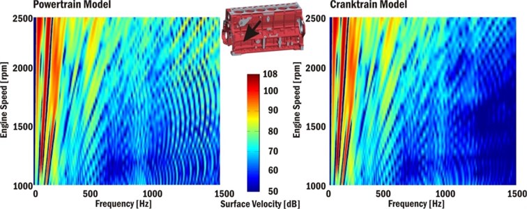
Fig. 7Campbell diagram of normal velocity of the bottom engine cover (oil sump) surface near second cylinder
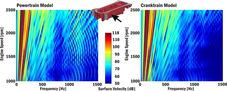
Campbell diagrams confirm previous results and in the case of the powertrain computational model show an increase of vibration levels in the frequency range 900-1400 Hz, mainly for high engine speeds. These vibrations are influenced by the gear timing drive and the injection pump torque. The incorporation of these influences leads to a more accurate solution of vibrations and noise produced by a powertrain.
6.2. Valvetrain computational model
A single valvetrain model complexity also has to be considered for complete valvetrain dynamic simulations. A single valvetrain model can include many special features but for general dynamics of a complete valvetrain some advanced features can be neglected. Generally, valvetrain dynamics is highly influenced by cranktrain vibrations, a gear timing drive and an injection pump. These influences can be correctly included only in the powertrain computational model. Valvetrain model comparisons include these models:
A powertrain model including a cranktrain, a valvetrain, a timing gear mechanism and an injection pump. Main components are modelled as flexible structures incorporating reduced FE models (a crankshaft, an engine block, a camshaft, rockers and valve springs).
An independent valvetrain model driven by a variable angular velocity computed from independent cranktrain dynamic solutions. The model does not include gear timing drive or fuel pump influences.
An independent valvetrain model driven by a constant angular velocity. The model does not include gear timing drive or fuel pump influences.
All valvetrain computational models are presented in Fig. 8.
Fig. 8Valvetrain computational models
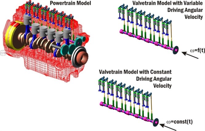
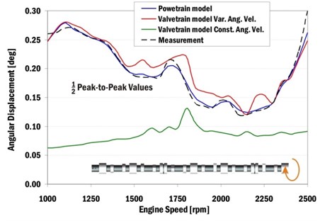
Fig. 9 presents a half of peak-to-peak values of camshaft end angular velocities in the place of camshaft bearing No. 1. Computational model results are compared with measurements performed by POLYTEC 4000 Series Rotational Laser Vibrometer.
The comparisons of computed and measured results show that the valvetrain model driven by constant angular velocity is not very accurate and should not be used for a camshaft dynamic solution of the target engine.
Fig. 9Half of peak-to-peak values of computed and measured angular velocities of a camshaft end in dependence on engine speeds
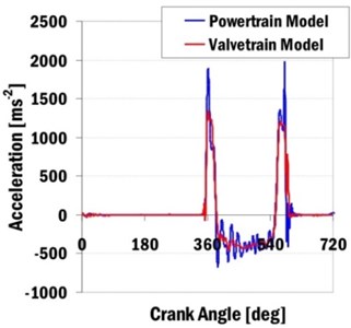
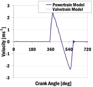
The complex powertrain model and the independent valvetrain model with variable angular velocities can be compared for single valvetrain dynamics too. Fig. 10(a) shows computed valve accelerations and Fig. 10(b) shows valve velocities. The presented results are valid for an intake single valvetrain of the first cylinder and an engine speed n= 2200 min-1.
Fig. 10Computed intake valve accelerations and valve velocities for engine speed 2200
a)

b)
The valvetrain model comparisons show some result divergencies. The complex powertrain model includes an additional frequency component which the valvetrain model does not include. These differences in results can be shown mainly in accelerations of valves. This frequency component is caused by the gear timing drive, together with the injection pump torque. It is mainly a tooth meshing frequency of meshing gears (for camshaft gear angular velocity 1100 min-1 and number of teeth 52, the resulted tooth meshing frequency is 953 Hz).
It is evident that the independent valvetrain models are not able to correctly describe dynamic phenomena, mainly for higher frequencies. These higher frequencies can significantly participate on powertrain acoustic emissions.
6.3. Gear timing drive
The gear timing drive of the target engine transfers relatively small nominal powers in comparison with, for example, gear trains. The nominal power of 2.85 kW is transferred from a crankshaft gear to an idler gear for an engine speed 2200 min-1. This power is divided into a camshaft gear component with 1.18 kW and an injection pump gear component with approximately 1.66 kW. The power balance does not consider any powers of other gears, as an oil pump gear which is very small and can be neglected.
While the power transmitted to gears is small in comparison with the engine power (125 kW) at the engine speed 2200 min-1, the peak torques on these gears are relatively high. Torsional vibrations of a crankshaft and a camshaft together with a torque of a mechanical controlled injection pump cause these high torque peaks. The tooth meshing frequency occurres at 953 Hz.
Fig. 11 shows gear wheel torques of the timing drive. Results demonstrate the differences between average and maximal values of gear torques. The greatest differences are in the case of the injection pump gear where the averaged value is 14.3 Nm and the maximal value is 230 Nm.
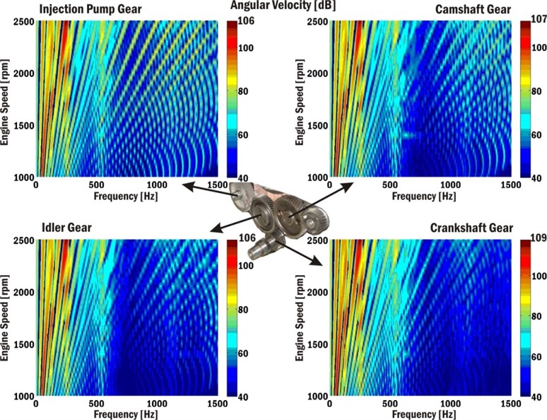
Fig. 12 presents Campbell diagrams of angular velocities of the timing drive gear for the whole engine speed range. There are areas of increased vibrations around the frequency 250 Hz and also 500 Hz. These increased vibrations are caused by torsional vibrations of the crankshaft and the camshaft. The vibrations with frequencies above 1000 Hz show influences of the variable stiffness of different meshing gears.
In the case of the target engine negative influences of timing drive meshing gears are significantly magnified by the injection pump torque. Generally, the gear timing drive considerably influences acoustic properties of the powertrain and together with gas pressure forces, cranktrain forces and valvetrain forces belongs to important noise sources.
Fig. 11Gear wheel torques of gear timing drive
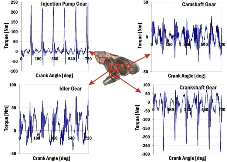
Fig. 12Campbell diagrams of angular velocities of timing drive gears
6.4. Injection pump influences
The mechanically controlled fuel injection pump influence and its loading torque influence, respectively, are evaluated with the help of the complex powertrain model incorporating a cranktrain without torsional damper. Different results with and without injection pump torques are compared.
The injection pump torque has very steep increase during a short time and many natural frequencies are excited by this torque.
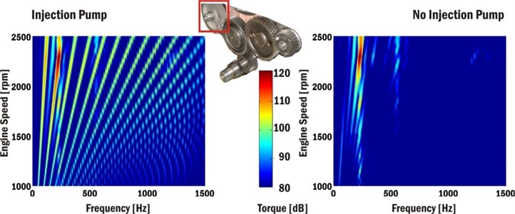
Injection pump torques significantly influence forces and torques between meshing gears of timing drive. Gear torques can be characterised by peak values. Fig. 13 shows torque results of the injection pump gear for engine speed 2200 min-1 computed for models with and without the injection pump.
Fig. 13Injection pump gear torque for engine speed 2200 min-1

Fig. 14 presents Campbell diagrams of an injection pump gear torque for the whole engine speed range using the torque reference value 10-5 Nm. Mainly frequencies about 255 Hz and 540 Hz in gear torque responses corresponding to the first and second crankshaft natural frequencies in the case of the model without an injection pump can be seen. Dominant harmonics orders are mainly 6th, 7.5th, 9th, 10.5th and 12th ones.
In the case of the model with an injection pump many additional frequencies corresponding to exciting frequencies of the injection pump torque are excited, and some of them are magnified in the areas of natural frequencies of gear wheels.
Fig. 14Campbell diagram of injection pump gear torque
Injection pump influences can be also found in axial movements of a crankshaft pulley. Fig. 15 shows crankshaft pulley axial movements relative to an engine block for the engine speed 2200 min-1.
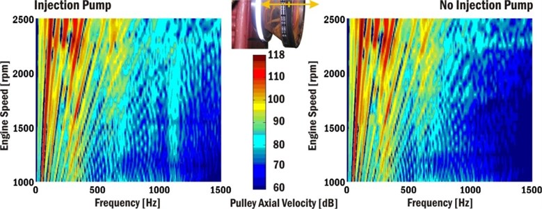
Campbell diagrams comparing absolute axial velocities of the crankshaft pulley are presented in Fig. 16. The differences can be seen mainly in the area of 1100-1200 Hz and they are caused by meshing gear forces excited by the injection pump torque. The reference velocity value 5.10-8 ms-1 is used for Campbell diagrams.
Fig. 15Axial movement of crankshaft pulley relative to engine block for engine speed 2200 min-1

Fig. 16Campbell diagrams of crankshaft pulley axial velocity
The most affected structures are those located close to the front end of the powertrain. The gear timing drive and the fuel injection pump occupy this part of the powertrain. The influences of the injection pump on powertrain noise can be presented using velocities of powertrain outer surfaces. Fig. 17 shows crankcase surface normal velocities near cylinder No. 1 and the crankshaft axis vs. crank angle for the engine speed 2200 min-1.
Fig. 17Normal velocity of crankcase surface near first cylinder and crankshaft axis
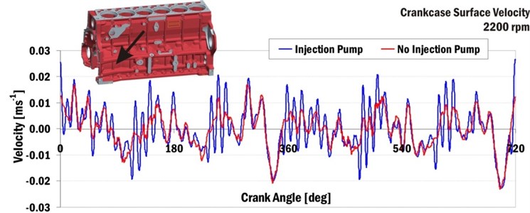
Fig. 18 presents Campbell diagrams of surface normal velocities near cylinder No. 2 and the crankshaft axis.
Fig. 18Campbell diagrams of crankcase surface velocities near the second cylinder and crankshaft axis
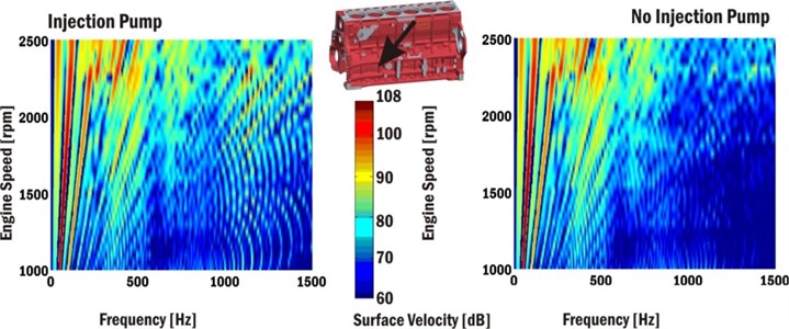
Fig. 19Normal velocity of bottom engine cover (oil sump) surface near to second cylinder
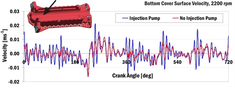
Injection pump influences can be also recognised on the bottom cover surfaces of the powertrain. The bottom cover of powertrain includes many natural frequencies in the frequency range from 700 Hz to 2000 Hz. Fig. 19 presents surface normal velocities of the powertrain bottom cover vs. crank angle for the engine speed 2200 min-1.
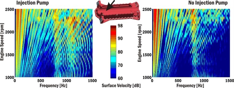
Fig. 20 shows Campbell diagrams of normal surface velocities of the powertrain bottom cover near cylinder No. 2. The presented results highlight that the natural frequency of the bottom cover occurs at 850 Hz.
Fig. 20Campbell diagrams of surface velocities of engine block bottom cover near cylinder No. 2
The mechanically controlled injection pump can have great impact on the gear timing drive. The impacts on a crankshaft fatigue, as well as, on a camshaft fatigue are relatively small. On the other hand, the impact on powertrain noise can be significant because the injection pump torque excites many natural frequencies of different structures. These resonances can negatively influence the powertrain noise.
7. Conclusions
The results of the work show that the most accurate computational models for solutions of noise and vibration are the complex powertrain models. These models also enable to understand interactions among different powertrain subsystems. The fact that all the results are computed by one computational model and stored in one result file is also an advantage.
The greatest disadvantage lies in high model complexity. The complex computational models require a high number of parameters to be inputted, which are often hard to find. Other disadvantages are: long solution times to solve the models numerically and sometimes a large storage place required for computed results.
Influences of other powertrain subsystems, gear timing drive or injection pump influences, on noise and vibrations are significant. Injection pump torques, in particular, can excite many different resonances of powertrain structures.
The large computational models of the powertrain, incorporating the most significant powertrain subsystems, have to be used. Engine block models using reduced FE bodies should include parts, i.e. covers, caps and intake or exhaust manifolds. All significant noise sources, as combustion pressure forces, meshing gear forces or injection pump torques, have to be also included into the powertrain model.
References
-
Beidl C., Rust A., Rasser M. Key Steps and Methods in the Design and Development of Low Noise Engines. SAE Technical Paper Series, 1999-01-1745, 1999.
-
Gold P., Schelenz R., Pischinger S. Acoustical investigation on the engine – transmission interaction. MTZ, Vol. 2013, Issue 12, 2013.
-
Drab C. B., Engl H., Loibnegger B. Application oriented dynamic simulation of elastic multibody systems. ECCOMAS – Multibody Dynamics, 2005.
-
Offner G. Multi-body Dynamics and Numerical Methods – Application for Internal Combustion Engines. Professorial Dissertation, Graz, Austria, 2006.
-
Yongxiang L., Lihong J., Wenquan S., Liwen N., Youjia Z. An efficient optimal design methodology for abnormal noise control of automobile transmission in the neutral idle condition. Journal of Vibroengineering, Vol. 16, Issue 1, 2014, p. 351-359.
-
Fakher Ch., Walid B. Effect of spalling or tooth breakage on gearmesh stiffness and dynamic response of a one-stage spur gear transmission. European Journal of Mechanics and Solids, Vol. 27, 2008, p. 691-705.
-
Anderson A., Vedmar A. A dynamic model to determine vibrations in involute helical gears. Journal of Sound and Vibration, Vol. 260, 2003, p. 195-212.
-
Ortmann Ch., Skovbjerg H. ADAMS/Engine powered by FEV, Part 1: valve spring. International ADAMS Users Conference, Rome, 2000.
-
Du I., Chen J. Dynamic analysis of a 3D finger follower valve train system with flexible camshafts. SAE 2000 World Congress, Detroit, Michigan, 2000.
-
Craig R. R. Structural Dynamics. 1st Edition, John Wiley and Sons, 1981.
-
Novotný P. Virtual Engine – A Tool for Powertrain Development. Inaugural Dissertation, Brno University of Technology, Czech Republic, 2009.
About this article
Outputs of this project, named NETME CENTRE PLUS (LO1202), were created with financial support from the Ministry of Education, Youth and Sports of the Czech Republic under the program supporting research, experimental development and innovation: “National Sustainability Programme I.” Authors gratefully acknowledge this support.
