Abstract
The on-bottom stability of submarine pipeline is a key problem of submarine pipeline design. The key issue is to simulate the interaction among wave, pipe and soil. The factors such as contact effect, frictional coefficient between pipe and soil, pipe’s penetration, the impact of yield stress are considered. Also, the results show that the computation of the pipe/soil interaction may provide a helpful tool for the engineering practice of pipeline on-bottom stability design.
1. Introduction
The theme for submarine pipeline on-bottom stability design is the instability criteria under various environmental conditions. To avoid the occurrence of pipeline on-bottom instability, i.e. the pipe breakouts from its as-laid original site, the seabed must provide enough soil resistance to balance the hydrodynamic loads upon the untrenched pipelines. The on-bottom stability of a submarine pipeline involves complex interactions between the wave/current, the untrenched pipeline and the neighboring soil.
In the recent decades, numerous experimental studies on the pipeline on-bottom stability have been carried out. Many foreign scientific institutes [1-4] have conducted the further research to the pipe/soil interaction of the untrenched pipe by the cyclic loading. The main conclusions are: the hydrodynamic force induced by wave and current can lead to the pipe’s additional penetration, and the soil lateral moundings beneath the pipe will take place when the pipe’s lateral displacement happens, these will cause that the soil’s lateral resistance is larger than Coulomb friction force, so the lateral resistance coefficient larger than Coulomb friction coefficient. They also put forward the pipe/soil interaction model, as shown in Fig. 1. The above experimental results are reflected in the Veritect’s and AGA’s design guidelines [5].
Fig. 1Pipe/soil interaction
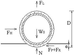
The ultimate soil resistance is defined as the maximum soil resistance to the untrenched pipe against on-bottom instability under the action of environmental loadings including waves, currents, etc. In the pipe-soil interaction model proposed by Wagner et al. (1989) [6], the ultimate soil lateral resistance (FRU) was assumed as the sum of the two components, i.e. the sliding resistance component and the passive soil resistance component:
where the passive soil force (the second component) modeling the resistance offered by the sand in front of the slightly embedded pipeline is expressed as the effective (buoyant) unit weight of sand (γ') multiplied by a characteristic area (A) and an empirically determined coefficient (β). The empirical coefficient (β) is a function of the pipe displacement and the lateral loading history (see [6] Wagneret al., 1989).
Lyons [7] has conducted the computation of the untrenched pipe, adopted nonlinear elastic model and static method. Gao et al. [8] has proposed an improved analysis method for the on-bottom stability of a submarine pipeline which is based on the relationship between Um/gD 0.5 and Ws/D2. Gao et al. [9] has employed a hydrodynamic loading method in a flow flume for simulating ocean currents induced submarine pipeline stability on a sandy seabed. Liu Jing [10] has simulated the interaction among flow, pipe and soil. The factors such as contact effect, frictional coefficient between pipe and soil, buried depth, pipe radius. Based on the numerical results the vertical displacement and hoop stress should are underestimated dramatically without considering the contact effect in the case of smaller buried depth. Meanwhile, porous water pressure in coarse sand attenuates slower than that of in fine sand, so pipe embedded in fine sand is more stable and safer than that in coarse sand.
In this paper, the numerical method has been used to simulate the pipe-soil interaction by using dynamic analytical method.
2. Computation model
2.1. Mathematical formulation
To choose the soil’s constitutive model is an important factor in the geotechnical engineering. In this paper two different models are adopted, such as Duncan-Chang nonlinear elastic, Ramberg-Osgood model. The mathematical formulation are as follows and parameters needed are shown in Tables 1, 2, 3.
Table 1Soil characteristics for Duncan-Chang nonlinear elastic model
Cohesion C (kPa) | Angle of internal friction ϕ (°) | Saturated density ρsat (kg/m3) | Failure rate Rf | Experimental constant K | Experimental constant n | Experimental constant G | Experimental constant F | Experimental constant D |
0.0 | 40 | 0.85 | 410 | 0.60 | 0.34 | 0.09 | 420 |
Table 2Soil characteristics for Ramberg-Osgood model
Elastic modulus (N/m2) | Poisson’s ratio μ | Hard parameter of nonlinear term n | Shear stress τy (Pa) | Yield offset α |
5×10⁵ | 0.35 | 5 | 3×10⁴ | 1 |
Table 3Pipe parameters
Elastic modulus (N/m2) | Poisson’s ratio |
210×109 | 0.3 |
The Duncan-Chang nonlinear model is:
Among which: c, ϕ – shear strength quota, Pa – atmosphere pressure, σ1, σ3 – axial principal stress, K, Rf, n, G, F, D – undecided parameter.
The Ramberg-Osgood model is:
Among which: G0 – shear module, γ – shear stress, τ – shear stress, τy – yielding stress, n –nonlinear hardening parameter, α – yielding offset.
3. Finite element model
3.1. Finite element model and boundary conditions
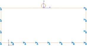
Because the seabed foundation is a semi-infinite space, the certain range should be chosen in the computation. In the computation, eight-node element is used for the pipe, the four-node element is used for the seabed, the finite element model is as shown in Fig. 2. Boundary conditions are as follows: far away from the pipeline, zero displacements at the both sides, the bottom, however, free boundary is used at the top.
Fig. 2Finite element model
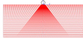
Fig. 3Boundary conditions
3.2. Constraint conditions
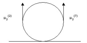
Actually the pipeline is constrained by the riser and its rotation stiffness, so the pipe cannot roll. But in two dimensional simulation, it is possible for the pipeline to roll on the seabed. So the constraint equation is adopted at both sides of the pipeline in order to prevent the pipe from rolling, as shown in Fig. 4.
The constraint equation is as follows:
Among which, 2 and 7 are the node number of both sides of the pipe separately.
Fig. 4Constraint equation
4. Numerical results
4.1. The displacement of pipe-soil system
From Figs. 5-8, we can conclude that the vertical displacement of the soil near to the pipe is larger than that of far away from the pipe. And also the two models’ results are different. Because the soil is elastic-plastic, the displacement of Ramberg-Osgood model is larger than that of the Duncan-Chang model.
Fig. 5Pipe-soil horizontal displacement of Dunchang-model
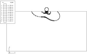
Fig. 6Pipe-soil vertical displacement of Dunchang-model
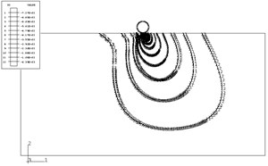
Fig. 7Pipe-soil horizontal displacement of Ramberg-Osgood model
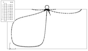
Fig. 8Pipe-soil vertical displacement of Ramberg-Osgood model
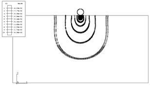
4.2. The relationship between time and stress
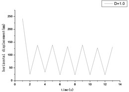
From Figs. 9-12, we can conclude that because the load is fluctuating, and also the time is changing, so the stress and displacement are dynamic with the time.
Fig. 9The relationship between time and tangent stress
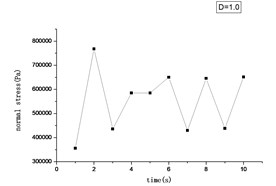
Fig. 10The relationship between time and normal stress
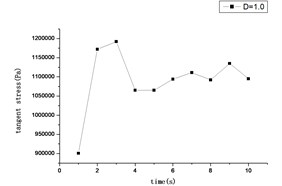
Fig. 11The relationship between time and vertical displacement
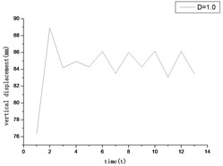
Fig. 12The relationship between time and horizontal displacement
4.3. Pipe’s penetration
From Fig. 13, the pipe’s diameter is 1.0 m, the Ramberg-Osgood model’s results are in accordance with the experiments, the nonlinear elastic model is smaller. This demonstrates that the Ramberg-Osgood model is in accordance with the experiment in penetration, but the nonlinear elastic model is smaller.
In which, z – pipe’s penetration, D – pipe’s diameter, Ws – submerged weight of pipe per unit length.
Fig. 13The comparability of computed penetration and experiment
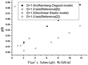
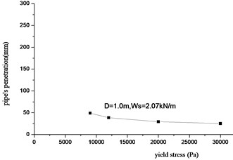
Fig. 14The relationship between penetration and yield stress
4.4. The impact of yield stress
For plastic model, if soil element’s stress exceeds yield stress, the soil will achieve yield state and destruction occurs. The impact of yield stress has been considered (see Figs. 15, 16).
From Fig. 14, the pipe’s penetration is increasing with the decreasing of yield stress. This is because that the yield stress is smaller, the stress of soil element is easy to get to the yield point, so some part of soil are destroyed, and cause pipe’s penetration to increase.
When analyzing the pipe-soil system, the Ramberg-Osgood model can explain the nature. When the yield stress is smaller, the Soil Lateral Mounding Phenomena is larger than that of the bigger yield stress, this is because that the yield stress is smaller, the soil element is easy to get to the yield point.
Fig. 15The pipe’s status when the yield stress is 3e3
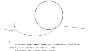
Fig. 16The pipe’s status when the yield stress is 6e3
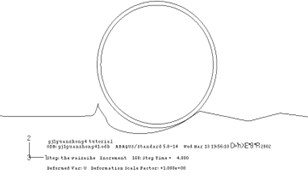
Fig. 17Relationship between lateral frictional force and penetration
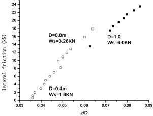
Fig. 18The comparison of resistance coefficient and test results
4.5. Lateral friction coefficient
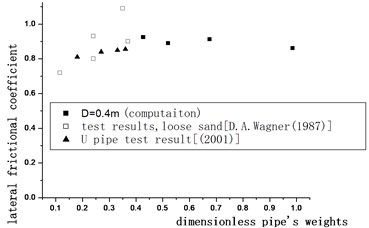
From Fig. 17, we can conclude that the lateral frictional force is affected by the following factors: pipe’s subweights, pipe’s diameter and pipe’s penetration. From Fig. 18, the computated lateral frictional coefficient is 0.897, it is larger than that of the average value of 0.888 of mechanical cyclic loading and the average value 0.83 of hydrodynamic load test.
5. Conclusions
1) The influence factors of soil lateral resistance: pipe’s subweights, pipe’s diameter, environmental conditions and pipe’s penetration.
2) The soil lateral mounding phenomena is changed with the yield stress.
3) According to the pipe/soil interaction analysis, the results may provide a helpful tool for the engineering practice of pipeline on-bottom stability design.
References
-
Brennodden H., Sveggen O., Wagner D. A., Murff J. D. Full-scale pipe-soil interaction tests. OTC Paper 5338, 1986.
-
Wanger D. A., Murff J. D., Brennodden H., et al. Pipe-soil interaction mod. Proceedings of Nineteenth Annual Offshore Technology Conference, 1987, p. 181-190.
-
Palmer A. C., Palmer Andrew, et al. Lateral resistance of marine pipelines on sand. Proceedings of 20th Annual Offshore Technology Conference, 1988, p. 399-408.
-
Allen D. W., Lammert W. F., et al. Submarine pipeline on-bottom stability: recent AGA research. Proceedings of 21st Annual Offshore Technology Conference, 1989, p. 121-132.
-
Det norske Veritas. On-bottom Stability Design of Submarine Pipeline, Recommended Practice E305, 1988.
-
Wagner D. A., Murff J. D., Brennodden H., Sveggen O. Pipe-soil interaction model. Journal of Waterway Port Coastal and Ocean, Vol. 115, Issue 2, 1989, p. 205-220.
-
Lyons C. G. Soil resistance to lateral sliding of marine pipelines. Proceedings of Fifth Annual Offshore Technology Conference, 1973, p. 479-484.
-
Gao Fuping, Jeng D. S.,Wu Y. X. Improved analysis method for wave-induced pipeline stability on sandy seabed. Journal of Transportation Engineering, Vol. 132, Issue 7, 2006, p. 590-596.
-
Gao Fuping, Yan S. M., Yang B., Wu Y. X. Ocean currents-induced pipeline lateral stability on sandy seabed. Journal of Engineering Mechanics, Vol. 133, Issue 10, 2007, p. 1086-1092.
-
Gao F. P., Xi-Ting Han, et al. Submarine pipeline lateral instability on a sloping sandy seabed. Ocean Engineering, Vol. 50, 2012, p. 44-52.
About this article
This work is financially supported by the Importation and Development of High-Caliber Talents Projects of Beijing Municipal Institutions. The Fund number is 21301413105.
