Abstract
The vision-based displacement measurement system was developed, which using digital video camcorder to test the deformation of high-rise structures. It is more economical than contact and contact-less displacement sensors. A series of tests were conducted to investigate the precision, serviceability, and stability of the vision-based displacement method. The results show that, the proposed method can effectively test the dynamic displacement, moreover, the method can be effectively applied to test the displacement caused by vibration which contains various frequency components. Based on the system, the deformation of high-rise building structure was tested. The results show that, the displacement obtained by vision-based can illustrate the free-vibration characteristics of structure well, meanwhile, this method can test bidirectional displacement in shaking table test and practical engineering.
1. Introduction
Structural health under various vibration has been a cutting-edge technology and gained increasing concerns, especially in civil engineering community [1]. As one of the most important parameter to identify the dynamic characteristic of structures, displacement responses are frequently measured for civil infrastructures even though they have some difficulties to be measured which because it is difficult to install the reference points for contact-type displacement transducer, contactless-type displacement transducers, like Laser displacement meter, limited by testing range. Despite that, the movements of such structures can be monitored by laser Doppler effects, GPS systems. Many studies have been carried out on GPS-based displacement test and LDV [2-5], however, these measurements are quite costly, especially, the structure has long-span. Meanwhile, the listed methods are difficult to be applied in terms of the dynamic displacement due to errors in the data and a restricted sampling rate. Likewise, this problem arises in the shaking table test for high-rise building. Using the shaking table test to evaluate the dynamic behaviors of high-rise structure, the main measuring components are accelerations and displacements as members of the structural system. Generally, the accelerometer is attached to the structural specimen because acceleration is achieved as an absolute value. However, it is difficulty to acquire effective displacement data. Contact-type displacement transducer limit by installing the reference points, contactless-type displacement transducers, limited by testing range. Numerical integration form acceleration to displacement, is frequently adopted [6]. However, the accuracy and precision of the numerical integration method is a key problem.
With the rapid progress of photonics science and image processing technology, in various fields, such as automation technology industry [7], and medical practice the video camera is used for measuring an objects shape and the changes to its deformation. In civil engineering, vision-based test method has been reported in recent years [8-12]. This study proposes a method to measure the dynamic and real-time displacement using camera. On the basis, a series of tests were carried out investigate the precision of the method. After evaluating the usability of the method, the deformation of high-rise building is measured. Vision-based displacement test method can reduce the installation expenses and enhance the reliability of measured displacement data obtained by shaking table test for high-rise building.
2. The vision-based displacement measurement system
2.1. The vision-based displacement method
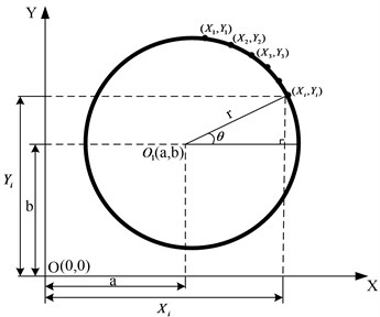
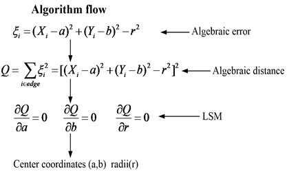
The important issues of the method are the circle detection algorithm and the calibrate relationship. The vision-based displacement test method was based on the basic principle of circle detection using the least squares method (LSM), LSM method uses the target circle’s edge point coordinates just doing one operation, and the target circle parameters (center coordinates and radii) can be obtained. The algorithm flow is shown in Fig. 1, in which, “edge” is the edge of target circle in the image, (Xi, Yi) is the edge point coordinates of target circle. The asymptotic time complexity of the algorithm is O(n), which has high computational efficiency.
Fig. 1Schematic diagram of algorithm flow
The calibration relationship between image pixel and actual displacement is illustrated in Fig. 2. From the Fig, it is clear that, at initial time, the center of target circle post in (X0, Y0), when at τ moment, the center of target circle moves to position (X1, Y1), relative pixel distance between center position (Xi, Yi) and initial position (X0, Y0) can be defined as ΔXi and ΔYi, ΔXi and ΔXi both can be accessed in terms of every time step. The radius of target circle in each image can be obtained through the circle fitting algorithm, Eq. (1) marks the average of radius of target circle:
In which, n is the total number of image, Ri is the radius of target circle in each image.
Take the radius of target circle equals 1 cm in actual space for example, the relationship between 1 cm in actual space and pixel in image space is: R (pixel)=1 (cm). Therefore, the horizontal displacement and vertical displacement in actual space are: Dx=ΔXi/R and DY=ΔYi/R, respectively.
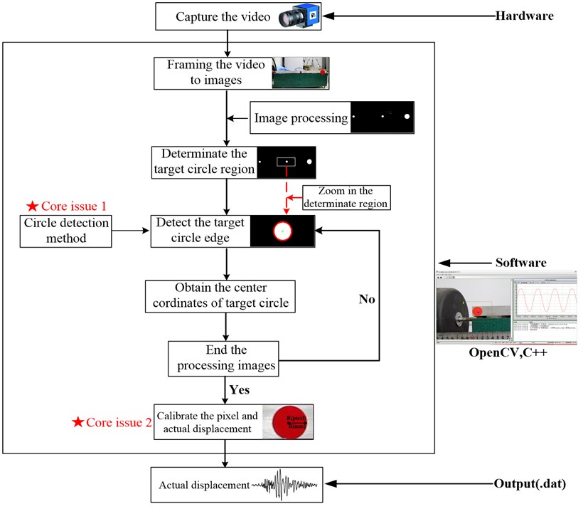
The flowchart of vision-based displacement test system is shown in Fig. 3. The video is captured by camera, and read by software. Center coordinates and radii of target circles can be obtained by the circle fitting algorithm. Then, the center coordinates are stored according to the continuous static image sequence; therefore, the horizontal and vertical displacements of the target circle center in the image space were obtained. By calibrating the relationship between the image pixels and coordinates of the actual objects, the actual displacement can be obtained. The self-developed software is based on the C++ and OpenCV.
Fig. 2Schematic diagram of calibration relationship between image pixel and actual displacement

Fig. 3The flowchart of vision-based displacement system
2.2. Verification on vision-based displacement measurement system
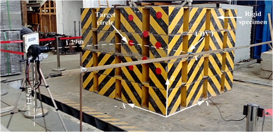
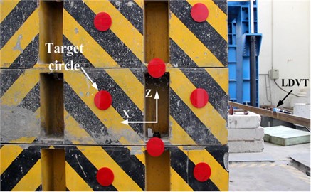
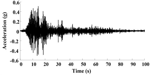
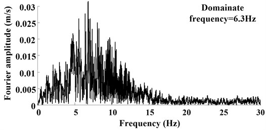
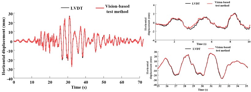
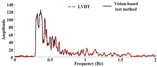
Fig. 4 shows the experimental condition. The displacement obtained by vision-based test method will be identical to the displacement measured by laser displacement meter (LVDT). Fig. 5 shows the displacement response under 1 Hz, 3 Hz input motion, it is clear that, the measurement of vision-based displacement test method is identical to that measured by LVDT. However, in practical engineering, the displacement may be causes by various vibration, such as earthquake, aeolian vibration, vortex-induced vibration which would contain various frequency components. In this research, Songpan ground motion (Ms8.0 Wenchuan Earthquake, China) was adopted as input motion to verify the proposed method. Acceleration time history curves and Fourier spectra are shown in Fig. 6, the dominant frequency of input motion is 6.3 Hz. Fig. 7 shows the displacement of the rigid specimen measured by vision-based displacement method and LVDT, it is clear that, the displacement measured from the LVDT and the displacement measured by proposed method was discovered to be similar, the proposed method can measure the dynamic displacement relatively well both in time-domain and frequency-domain.
Fig. 4The typical picture of experimental condition
a)
b)
Fig. 5Displacement response comparing the vision-based test method and actuator LVDT feedback under 1 Hz and 3 Hz

a)

b)
Fig. 6Ground motion acceleration time histories and Fourier spectra on the shaking table surface
a)
b)
Fig. 7Displacement response comparing the vision-based test method and actuator LVDT feedback under earthquake ground motion
a)
b)
To analyze the measured displacement results, the accuracy and precision of measurement results from this study are compared using percent error of Eq. (2), RMSE (root-mean-square error) of Eq. (3), in which, n is the total number of images, Vi is the displacement measured by vision-based displacement test method, Mi is the displacement measured by LVDT. Table 1 lists the obtained accuracy statistics of the development vision-based displacement test method and LVDT, it is clear that, under different input conditions, the proposed method always has an equal level of measurement degree to the LVDT feedback since the percent error was 1.75 % for 1Hz sine wave, 0.65 % for 3 Hz sine wave, 0.9 % for Songpan ground motion, respectively. The RMS error was 0.97 mm for 1 Hz sine wave, 0.31 mm for 3 Hz sine wave, 0.52 mm for Songpan earthquake, respectively. Thus, it is judged that the suggested displacement measurement method is able to evaluate the dynamic displacement:
Table 1Error analysis of proposed method
Test case | Input motion | Dominant frequency Hz | Percent error (%) | RMSE (mm) |
1 | 1 Hz sine wave | 1 | 1.75 | 0.97 |
2 | 3 Hz sine wave | 3 | 0.65 | 0.31 |
3 | Songpan earthquake | 6.3 | 0.90 | 0.52 |
Table 2The technology parameters of shaking table
Dimension: 6 m×6 m | Frequency range: 0.1-50 Hz | |||
Standard proof mass: 60 t | Maximum proof mass: 80 t | |||
Maximum capsizing moment: 180 tm | Maximum eccentric torque: 60 tm | |||
Direction | X | Y | Z | |
Acceleration (g) | Standard proof mass | ±1.5 | ±1.0 | ±0.8 |
Maximum proof mass | ±1.2 | ±0.8 | ±0.6 | |
Velocity (cm/s) | Continuous vibration | ±70 | ±90 | ±70 |
10 seconds vibration | ±100 | ±125 | ±80 | |
Displacement (cm) | ±15 | ±25 | ±10 | |
Table 3Similitude ratio of the model structure
Physical quantity | Similitude ratio | Physical quantity | Similitude ratio |
Length | 1/40 | Equivalent density | 6.683 |
Elastic modulus | 1/2.85 | Duration | 0.1091 |
Linear displacement | 1/40 | Velocity | 0.229 |
Frequency | 9.165 | Acceleration | 2.10 |
Dynamic strain | 1.000 | Gravitational acceleration | 1.0 |
Dynamic stress | 1/2.85 | Force | 0.0002193 |
3. Applied in high-rise building shaking table test
3.1. Test apparatus, test case and layout of sensors
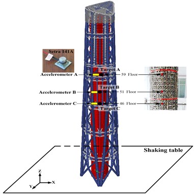
The dimension of shaking table was 6.0 m×6.0 m in plane in China Academy of Building Research (CABR). The maximum acceleration of shaking table was 1.5 g with the maximum proof mass of 80 tons, where g is the gravitational acceleration. The frequency of the input motion ranges from 0.1 to 50 Hz. The detailed technology parameters of the shaking table is listed in Table 2. The height of tested building is 11.008 m with 95 floors, the similarity ratios of model structure are shown in Table 3. 64 acceleration sensors (model: Setra 141A) were installed in different position of the building, the high-rise building and layout of sensors are shown in Fig. 8. In 46, 51, 59 floors, the targets were installed to compare the displacement data calculated by accelerometers, and correct the integration parameters. The test cases are shown in Table 4. The camcorder used in this test is Panasonic HDC-TM700, which has 1920×1080 pixels of resolution and is able to measure almost 60 frames per second, the optical equipment (such as lenses, and cameras, etc.) and target size play important roles in vision-based measurement system.
Table 4Test cases for the shaking table tests (Normalization in acceleration)
Test case | Acceleration records in X direction (m/s-2) | Acceleration records in Z direction (m/s-2) |
S835 | 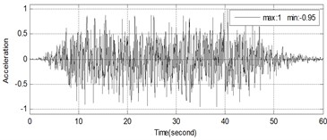 | None |
S836 | 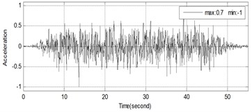 | 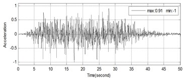 |
L840 | 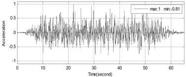 | None |
Fig. 8The high-rise building and layout of sensors
3.2. Results and analysis
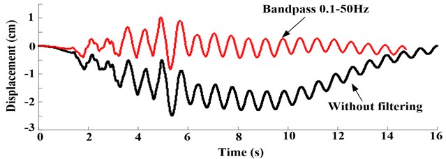
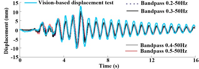
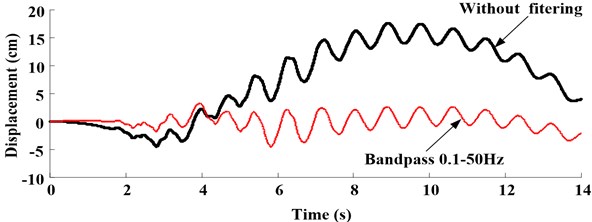
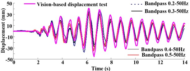
Figs. 9-10 depict the comparisons between the displacement measured by vision-based displacement test method and that obtained by integration form acceleration which installed in the 59 floor.
Fig. 9Displacement response comparing the vision-based test method and integration in test case S835 that the PGA is 0.2 g
a)
b)
Fig. 10Displacement response comparing the vision-based test method and integration in test case L840 that the PGA is 0.4 g
a)
b)
The results show that if integration without filtering, the displacement will drift. With the increase of low-frequency, the shapes of displacement show more reasonable comparison with real displacement, however, the peak of displacement measured by integration was less than that measured by vision-based displacement test method. This may be caused by noise existing in the experiment and the integral terms generated from integration process, which need to be proposed by baseline concretion and filtering. Generally, choose 1/3 first order natural frequency of structural system to filter the signal (in this test, the first order natural frequency of structural system before shaking is 1.53 Hz). The process will damp certain signals, which make signal energy falling.
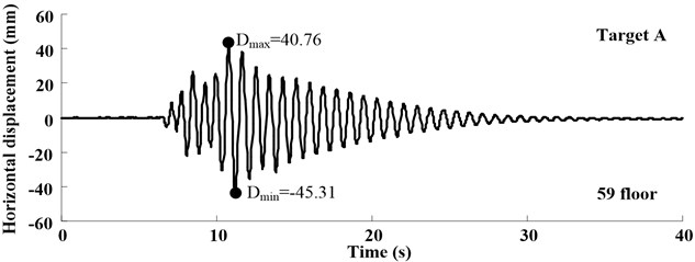
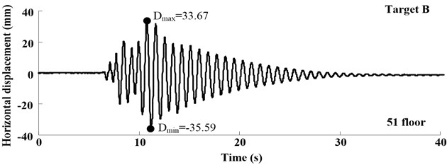
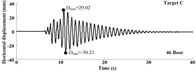
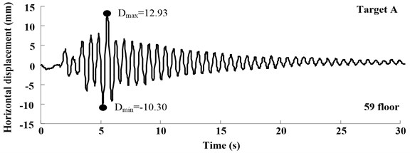
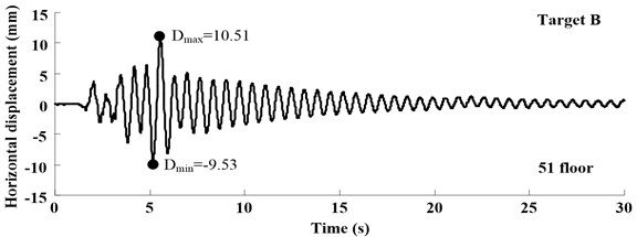
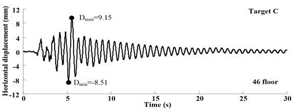
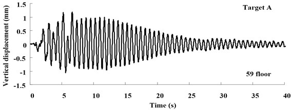
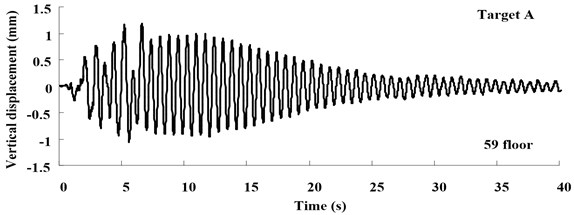
The time histories of displacement measured in Target A-C at different loading conditions are shown in Figs. 11-13, which illustrate the free-vibration characteristics of damping system. Moreover, at the test case in S836, when input multi-dimensional shaking, the one-way acceleration sensor can’t test bidirectional displacement, vision-based displacement can obtain both horizontal and vertical displacement.
Fig. 11Displacement response at different test position in test case L840 that the PGA is 0.4 g
a)
b)
c)
3.3. Discussion of the vision-based test method
The vision-based displacement method can only track the motions in flat surfaces (as X, Z axes in the shaking table test). The method cannot be performed on all axes (X, Y and Z axes), the binocular vision can solve this problem. Moreover, the measurement values are unstable depending on the movement of the camera support and are affected by the accuracy of their adherence to the target. Despite the disadvantages, the vision-based measurement can be applied to the locations where displacement transducer is difficult to attach and it can be in a bidirectional motion.
Fig. 12Displacement response at different test position in test case S835 that the PGA is 0.2 g
a)
b)
c)
Fig. 13Displacement response at different test position in test case S836 that the PGA is 0.2 g
a)
b)
4. Conclusion
The vision-based displacement measurement method has been proposed. A series of shaking table tests were conducted to investigate the precision, serviceability, and stability of the vision-based displacement method. The test results showed good agreement between two displacements measured from the vision-based system and the laser displacement sensor as a reference. Based on the system, the deformation of high-rise building structure was tested. The results show that, the displacement obtained by vision-based method can illustrate the free-vibration characteristics of structure well, meanwhile, this method can test bidirectional displacement in shaking table test. It is expected that if image noise or periodic noise is reduced through image signal process, a more accurate displacement response measurement is possible. And it is also expected that with a high resolution and high speed image acquisition equipment, more accurate displacement responses and high frequency displacement responses is possible.
References
-
Stull C. J., Hemez F. M., Farrar C. R. On assessing the robustness of structural health monitoring technologies. Structural Health Monitoring, Vol. 11, Issue 6, 2012, p. 712-723.
-
Yi T. H., Li H. N., Gu M. Characterization and extraction of global positioning system multipath signals using improved particle filtering algorithm. Measurement Science and Technology, Vol. 22, Issue 7, 2011, p. 1-11.
-
Yi T. H., Li H. N., Gu M. Experiment assessment of high-rate GPS receivers for deformation monitoring of bridge. Measurement, Vol. 46, Issue 1, 2013, p. 420-432.
-
Nassif H. H., Gindy M., Davis J. Comparison of laser Doppler vibrometer with contact sensors for monitoring bridge deflection and vibration. NDT&E International, Vol. 38, Issue 3, 2005, p. 213-218.
-
Guo J. J., Jiang J. J. Time-frequency analysis of a suspension bridge based on GPS. Journal of Sound and Vibration, Vol. 254, Issue 1, 2002, p. 105-116.
-
Park K. T., Kim S. H., Park H. S., Lee K. W. The determination of bridge displacement using measured acceleration. Engineering Structure, Vol. 27, Issue 3, 2005, p. 371-378.
-
Ragulskis M., Maskeliunas R., Saunoriene L. Identification of in-plane vibrations using time average stochastic moiré. Experimental Techniques, Vol. 29, Issue 6, 2005, p. 41-45.
-
Lee J. J., Shinozuka M. A vision-based system for remote sensing of bridge displacement. NDT&E International, Vol. 39, Issue 5, 2006, p. 425-431.
-
Choi Hyoung-Suk, Cheung Jin-Hwan, Kim Sang-Hyo, Ahn Jin-Hee Structural dynamic displacement vision system using digital image processing. NDT&E International, Vol. 44, 2011, p. 597-608.
-
Ye X. W., Nim Y. Q., Wai T. T., et al. A vision-based system for dynamic displacement measurement of long-span bridges: algorithm and verification. Smart Structures and Systems, Vol. 12, 2013, p. 363-379.
-
Wahbeh A. M., Caffrey J. P., Masri S. F. A vision-based approach for the direct measurement of displacements in vibrating systems. Smart Mater Structures, Vol. 12, 2003, p. 785-794.
-
Yoneyama S., Muramatu M., Saka M., Nanbara K., Ueda H. Bridge deflection measurement using digital image correlation with camera movement correction. Material Transactions, Vol. 53, Issue 2, 2012, p. 285-290.
About this article
The authors gratefully acknowledge the financial support to this study by the Major Research Plan Integration Project of the Natural Science Foundation of China (Nos. 91215301, 51421005, 51508526) and by the Project of Construction of Innovative Teams and Teacher Career Development for Universities and Colleges Under Beijing Municipality (Nos. IDHT20130512, IDHT20130507).
