Abstract
The time and frequency forced responses for the permanent magnetic planetary gear drive were computed and analyzed. The influence of air gap between sun gear and planetary gear to frequency forced responses is discussed. Results show that the changes of air gap have obvious effects on the low frequency vibration amplitude of elements. When air gap is too large or too small, it will seriously affects the dynamic performance of the system. So, selecting rational system structure parameters is very important, which can avoid system elements generating larger vibration.
1. Introduction
Magnetic transmission is without wear and noise. This mechanical transmission is suitable for the fields such as chemical equipment, medical apparatus and food processing equipment, etc. [1]. Domestic and foreign scholars has done further research on the magnetic gear drive mechanism and structure design. But the early magnetic gear has single driving mode, and only a few magnetic pole pair is at the magnetic coupling state at any time in the operation process, which lead to small transmission torque and low torque density. It limits the application of the drive. Hence, a planetary magnetic gear drive was proposed. Huang C. C. et al. designed the 2K-H type permanent magnetic planetary gear transmission mechanism, and completed the calculation and analysis of system static torque based on the finite element method [2]. Noboru Niguchi et al. performed simulation of dynamic torque of the mechanism with three-dimensional finite element method, developed the experimental prototype, and validated the simulation results of torque characteristics by experimental test [3]. Xu Lizhong et al. applied analytic method to analyze the torque characteristics and free vibration of the permanent magnetic gear transmission system [4, 5]. However, permanent magnetic planetary gear transmission is magnetic coupling system, design parameter which influences magnetic coupling force will seriously affect the dynamic behavior of the system. Especially when the excitation frequency is close to the natural frequency of the system, the system will lead to a strong resonance. In order to select the suitable design parameters and guarantee the good dynamic characteristics of transmission system, the forced vibration of permanent magnetic planetary gear driving system must be researched.
2. The working principle of permanent magnetic planetary gear drive
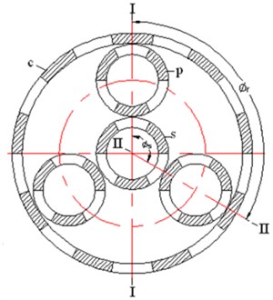
The drive consists of four basic elements as shown in Fig. 1: planetary gears, sun gear, crown gear, and a rotor which forms the central output shaft upon which the planetary gears are mounted. The planetary gears and the others have permanent magnets instead of teeth. The N and S polar permanent magnets are mounted alternately on each gear. If a specific relation between the drive parameters is given, N pole of one element will correspond to S pole of the other one all along. The attractive forces between N and S pole of the different elements are driving forces and the meshing without contact are realized. By means of magnetic forces between teeth of the planetary gears and other gears, the rotor is driven to rotate around its own axis. Thus, a power of low speed and large torque is output.
Fig. 1The magnetic planetary gear drive
3. Calculation of the system forced vibration frequency response
Reference [5] established the dynamic calculation model of the 2K-H type permanent magnet planetary gear driving system, based on which a motion differential equation considered the system damping was established:
where, M is the system mass matrix, C is the system damping matrix, K is the system stiffness matrix, q is system generalized coordinates array, xj, yj and uj were X, Y direction displacement and torsional displacement of planetary arm, the inner gear ring, a sun wheel and the planetary wheel respectively, and F is external excitation, which is defined as:
System regular modal matrix was introduced as follow:
From this, system regular mass matrix, regular damping matrix, regular stiffness matrix and the regular vibration force vector were calculated as follows:
FN=Tsrssinωst[ϕ(9)1ϕ(9)2⋯ϕ(9)3N+9]T-Trrrsinωrt[ϕ(3)1ϕ(3)2⋯ϕ(3)3N+9]T.
Regular motion differential equation with damping of permanent magnetic planetary gear drive system is defined as:
γi is i order regular relative damping coefficient, then the i order regular motion differential equation can be written as:
i order regular displacement time response leads to:
+1ωri∫t0FNi(t')e-γiωi(t-t')sinωri(t-t')dt',
where ωri=ωi√1-γ2i, the initial conditions were˙qNi0=0,qNi0=0 and FNi=Tsrssinωstϕ(9)i-Trrrsinωrtϕ(3)i, which was fed into Eq. (3), after many times of prosthaphaeresis and using integration by parts, the problem can be solved as:
+(ωs-ωri)sinωrit+γiωicosωritω2s+ω2i-2ωsωri]+(ωs+ωri)sinωst+γiωicosωstω2s+ω2i+2ωsωri
-(ωs-ωri)sinωst+γiωicosωstω2s+ω2i-2ωsωri}-12ωriTrrrϕ(3)i
∙{e-γiωit⋅[(ωr+ωri)sinωrit-γiωicosωritω2r+ω2i+2ωrωri+(ωr-ωri)sinωrit+γiωicosωritω2r+ω2i-2ωrωri]
+(ωr+ωri)sinωrt+γiωicosωrtω2r+ω2i+2ωrωri-(ωr-ωri)sinωrt+γiωicosωrtω2r+ω2i-2ωrωri}.
The time domain response in original coordinates is:
The system frequency transmission function was deduced by the Laplasse transformation of Eq. (2):
Using Eq. (6), the system frequency response can be calculated.
4. The analysis of frequency response of forced vibration
The external excitation of permanent magnetic planetary gear driving system is output torque of planetary arm and intput torque of sun gear. Most of the time, the input excitation and output excitation effect at the same time, so using numerical simulation software MATLAB, combined Eq. (5) and Eq. (6) system frequency response can be obtained. The example system parameters such as shown in Table 1. Ij is moment of inertia and rj is radius of base circle, where j represents planetary arm, ring gear, sun gear, sun gear and planetary gears respectively.
4.1. The analysis of frequency response (double excitation)
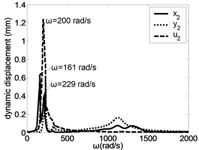
When the input excitation Ts/rs is 17.62 N and the output excitation Tr/rr is 35.46 N, the forced frequency responses of the system were studied as shown in Fig. 2. When the harmonic excitation force of input shaft and output shaft equal, the system components will produce intense vibration near different natural frequencies. Literature [6] introduced the vibrating modes of the magnetic planetary gear drive, which include the torsion mode of central elements, the translation mode of central elements and the planetary gear mode. Under different vibration modes, the maximum displacement of system resonance is different. When the excitation frequency is close to the low order natural frequency, most of system components will have the obvious resonance. When the exciting frequency is close to the high order natural frequency, the translational vibration of the various components occurs obviously, but the torsional resonance is very small besides ur, uc and us. The vibration modes has little influence on the maximum resonance amplitude of xsand us, while has large influence on the maximum resonance amplitude of other directions.
Table 1Basic parameters of drive system
Basic parameter | Planetary arm | Ring gear | Sun gear | Planetary gears |
Mass (kg) | 0.5393 | 0.4556 | 0.078 | 0.078 |
Ij/r2j (kg) | 0.2696 | 0.0595 | 0.0385 | 0.0385 |
Radius of base circle (mm) | 36.1 | 60 | 18 | 18 |
Radial support stiffness (kN/m) | 5 | 5 | 5 | 5 |
Tangential support stiffness (kN/m) | 0 | 50 | 0 | 0 |
Meshing stiffness (kN/m) | 18.7 | 10.2 |
Fig. 2The forced frequency responses of the system
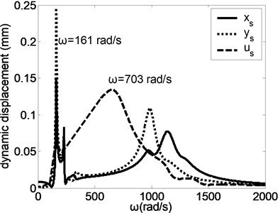
a) Planetary arm
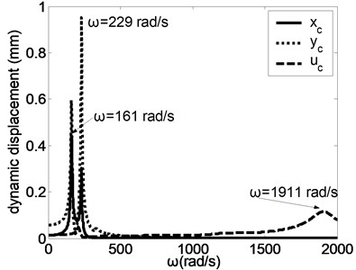
b) Ring gear
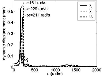
c) Sun gear
d) Planetary gear 1
4.2. The influence of magnetic parameters on the forced frequency response
Magnetic induction, magnetic pole pair, the gap of magnetic gear and the axial thickness of magnetic gear are important parameters which influence the magnetic properties of the driving system. The effect of these parameters on frequency response must be researched. Take the air gap as an example, the translation and torsion direction variation of frequency and amplitude with this parameter was studied detailedly.
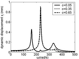
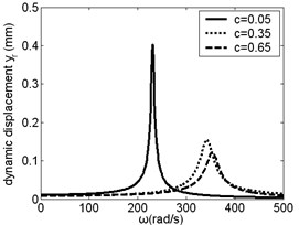
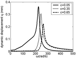
The air gap between the sun gear and the planetary gear is c. When c equals 0.05 mm, 0.35 mm and 0.65 mm, the effect of c on resonance frequency and amplitude of planetary arm was studied, as shown in Fig. 3, from which it was found that the resonance frequency increased with c increasing. When c is small, the change of resonance frequency with c is obviouse. When ω< 300 rad/s, resonance amplitude of planetary arm in x direction increased with c increasing. But when ω is between 300 rad/s and 400 rad/s, resonance amplitude decreased with c increasing.
Fig. 3Frequency response of planetary arm changes along with c
a)xr
b)yr
c)ur
The effect of c on resonance frequency and amplitude of inner ring gear was studied, as shown in Fig. 4. When ω is small, the resonance frequency keep unchanged with c increasing. But when ω is near 2000 rad/s, resonance amplitude of inner ring gear in u direction decreased with c increasing. The change of c has certain influence on low frequency resonance amplitude of inner ring gear in x, y and u direction and high frequency resonance amplitude in u direction, but the influence on the resonance frequency is not obvious.
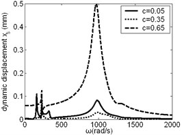
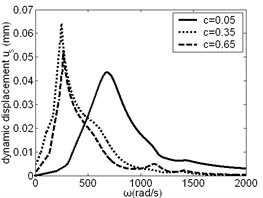
The effect of c on resonance frequency and amplitude of sun gear was studied, as shown in Fig. 5, from which it was found that the change of c has large influence on low frequency and high frequency resonance amplitude of sun gear in x and y direction, but the influence on the resonance frequency is small. The change of c has certain influence on intermediate frequency and high frequency resonance amplitude of sun gear in u direction.
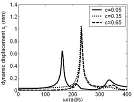
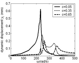
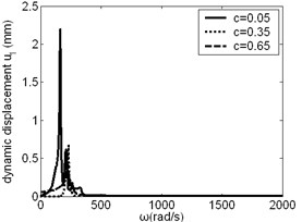
The effect of c on resonance frequency and amplitude of planetary gear was studied, as shown in Fig. 6. When c is small, its change has obvious effect on low frequency vibration of planetary gear in y and u direction. When c is large, its change has influence on low frequency vibration of planetary gear in x direction.
Fig. 4Frequency response of inner ring gear changes along with c
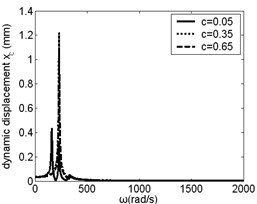
a)xc
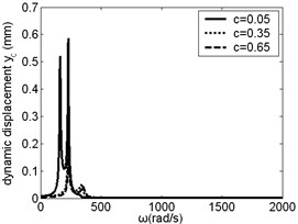
b)yc
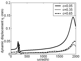
c)uc
Fig. 5Frequency response of sun gear changes along with c
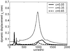
a)xs
b)ys
c)us
Fig. 6Frequency response of planetary gear changes along with c
a)x1
b)y1
c)u1
5. Conclusions
Based on the forced vibration equation for the permanent magnetic planetary gear drive system, the frequency forced responses with double excitation are computed and analyzed, the influence of air gap between the sun gear and the planetary gear to frequency forced responses is discussed. Results show that the magnetic parameter had obvious effects on the low frequency vibration amplitude of elements. Selecting rational system structure parameters is very important, which can avoid system elements generating larger vibration.
References
-
Tsurumoto K., Kikuchi S. New magnetic gear using permagnet. IEEE Transactions on Magnetics, Vol. 23, Issue 5, 1987, p. 3622-3624.
-
Huang C. C., Tsai M. C., Dorrell D. G., et al. Development of a magnetic planetary gearbox. IEEE Transactions on Magnetics, Vol. 44, Issue 3, 2008, p. 403-412.
-
Niguchi N., Hirata K. Transmission torque analysis of a novel magnetic planetary gear employing 3-D FEM. IEEE Transactions on Mganetics, Vol. 48, Issue 2, 2012, p. 1043-1046.
-
Zhu Xuejun, Xu Lizhong Design of parameters and analysis of torque for permanent magnetic epicyclic gear drive. Journal of Mechanical Engineering, Vol. 21, Issue 5, 2010, p. 529-535.
-
Zhu Xuejun, Xu Lizhong Sensitivity analysis of permanent magnetic planetary gear drive. Journal of Mechanical Engineering, Vol. 24, Issue 4, 2013, p. 468-476.
-
Xu Lizhong, Zhu Xuejun Natural frequencies and vibrating modes for a magnetic planetary gear drive. Shock and Vibration, Issue 19, 2012, p. 1385-1401.
