Abstract
This paper presents results of simulation of visco-elastic dampers based on the model of the vehicle shock absorber. The aim of this research is to determine the parameters of dynamic models of special dampers applicable in advanced vehicle suspension systems. One of the key issues of modeling is to determine the acceptable degree of the simplification. Model reduction is based on the determination of the damping coefficient suitable for testing vibration control systems. The diagnostic model of the shock absorber takes into account features such as nonlinearity and asymmetry of damping characteristics. It is also important to take into account the apparent elasticity of the hydraulic damper. Damping and stiffness characteristics of automotive shock absorbers are identified by the proposed algorithm. The obtained results proove that the resulting damper stiffness is an important factor which cannot be neglected at higher frequencies of cyclic load.
1. Introduction
The collection of diagnostic database requires obtaining diagnostic information during the experiments on the real objects or simulation studies. Studies of real objects are often time-consuming and very expensive [1-6]. The simulation studies are alternative solution. It allows acquisition of diagnostic knowledge with the help of a computer and appropriate software. The task of diagnosing of technical object often necessitates troubleshooting based on the early symptoms of the condition. In practice, the use of vibro-acoustic method involves the analysis of low-energy signals disorders. In this case, the necessary condition is to use a specific model [7-9], which best reflects reality. Diagnosis according to the model opens up huge possibilities. Assess of the current technical condition and analysis of the future development of damage allow for the use of effective countermeasures. The great advantage of diagnostic simulation is the possibility to optimize the process control operation [10-15]. The materials and productions issues can be affected on further damages of shock absorber elements as well [16-19].
The fundamental role of shock absorber is reduction of relative movements of sprung and unsprung masses. The essence of the problem is that, despite the relative ease of construction of the shock absorber of the vehicle, it has complex non-linear dynamic properties. Initial assumptions of how the damper works in operation are gradually changing. The impact of these changes is significant for the comfort and safety of travelling. The operational simulations of automotive suspension difficulty lie in the proper selection of the parameters of the damper. Sometimes, in order to avoid these drawbacks, the hardware-in-the-loop method was used. More convenient solution is to use properly identified computational model of the damper [9, 20]. The aim of the study was to determine the model parameters of nonlinear viscous damper on the example of the automotive shock absorber.
2. Modeling of automotive vibration dampers
The simulations of suspension dynamics of vehicles are commonly used procedures for large simplification of the model. The greatest possible simplification of the model is in the form of constant damping coefficient. Depending on the main aim to conduct simulation studies, this approach is often justified, for example in simple models with two degrees of freedom used to test algorithms for vibration control. In this case, a mathematical model of suspension has the following form:
m1¨z1-c2(˙z2-˙z1)+c1(˙z1-˙h)+k1(z1-h)-k2(z2-z1)=0,
where: m2 – sprung mass, m1 – unsprung mass, k1 – stiffness of wheel, k2 – stiffness of suspension, c2 – damping of suspension, c1 – damping of wheel, h – excitation, z2 – vertical displacement of sprung mass, z1 – vertical displacement of wheel.
Characteristic of vehicle dampers are non-linear and very often asymmetric with respect to the origin of coordinate system [11, 21, 22]. Non-linear damping force vs. relative velocity of the damper piston is modeled using function (e.g. polynomial of n-th degree). It's determined separately for the movement during reflection and deflection.
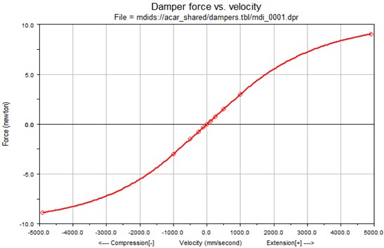
In modeling of the nonlinear damping characteristics of the shock absorber the theory of spline functions was used. The non-linear damper model is defined by a set of basic points by which the characteristic curve is carried and calculated using spline functions.
Such models can be found in commercial programs for the analysis of dynamic phenomena occurring in vehicles (Fig. 1).
In any previously reported examples of modeling of the damping characteristics the unequivocal of the instantaneous value of the force generated by the shock to the instantaneous velocity of the relative motion of the piston and the housing of the damper was assumed. Such an assumption implies that the shock absorber of car is part of a viscous damping force and depends on the resistance to motion in all conditions only on the speed of extortion.
Fig. 1The base model of damping characteristic of shock absorber in the ADAMS/CAR defined by basis points and spline functions
This is a major limitation of the adequacy of the discussed models of dynamic damper to the range of low-frequency excitations, the value of which does not exceed 0.5 [Hz]. For such excitations the resulting damper stiffness is small and its impact on value of the damping characteristics force is negligible.
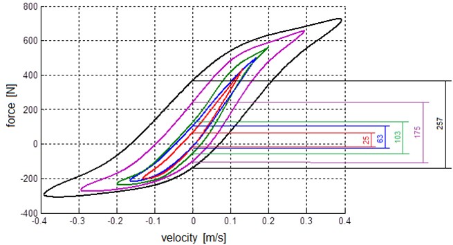
For the analysis of the dynamics of the damper for higher frequency vibrations influence of those parameters is significant. The phenomenon of the resulting damper stiffness was measured in the damping force identification stand and the results are illustrated in Fig. 2.
The resulting damper stiffness can be approximated being directly proportional to the force in the area around near zero velocity (Fig. 2). Thus, the force generated by the shock absorber is the sum of two components: the resulting damper stiffness and damping [23, 24].
Fig. 2The loop diagrams of damping force for sinusoidal extortions at various frequencies; the effect of the resulting damper stiffness is obvious
Another aspect of examining the accuracy of computational models is phenomenon of the impact of shock stroke length on the shape of the damping characteristics. In the case of a sinusoidal extortion the maximum force obtained for velocity reciprocating motion of the piston damper always gets the time for which the offset value is equal to zero, assuming that the origin of the coordinate system is positioned in the middle of the length of the working stroke. The occurring maximum value of the velocity can be achieved in two ways – by increasing the length of the working stroke for fixed frequency or for a constant stroke length by changing the frequency of extortion. Designated by such methods damping characteristics are affective only when using the low-frequency excitations. In real traffic conditions, vehicle vibrations are from a wide range of frequencies and the velocity of move the piston of shock absorber of a few m/s are both long and short strokes working. For this reason, it is appropriate considering the damping characteristics of the shock absorber as a function of two-arguments.
Property discussed hydraulic shock absorber raises a question regarding the required level of detail of the model dynamic damper, which will be the basis for the development of diagnostic measures. For the developed model the following assumptions have been set:
– Take into consideration stiffness of the damper,
– Define the damping characteristics as a function of two-arguments.
3. A dynamical model of shock absorbers
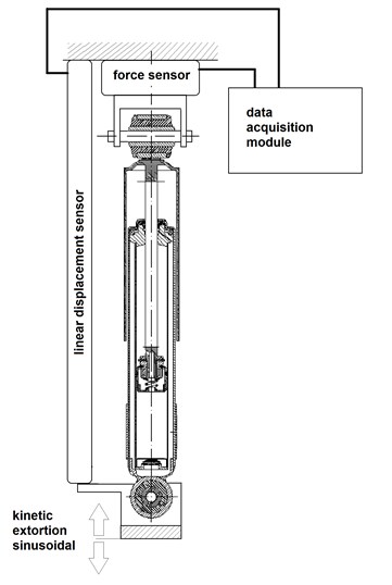
Car shock absorbers were tested according to the scheme shown in Fig. 3. The kinematic sinusoidal force was used during the research. The parameters such as duration and amplitude were chosen as combination which gave the same values of the maximum velocity of movement extortion.
The results were registered for each test frequency to collect a series of files, which contain the forces generated by the shock absorber, the corresponding values of traverse of the piston damper and the sampling frequency. In order to determine the damping characteristics of the shock absorber based on working characteristics the maximum values of forces in tension and compression were determined. These are the times where the velocity of the reciprocating motion was maximal.
This method allows to obtain from the working stroke of the shock absorber the series of damping force values for subsequent frequency domains. For each test the frequency was selected for the condition that each row in the table obtains the same value of the maximum velocity of movement.
Due to the limitations of research capabilities the table of values the damping forces of the shock absorber contains blank cells for small values of the working stroke. The values of the damping forces for these cells were taken a-priori.
Fig. 3The scheme of measurement system
Graphical representation of the shock absorber damping characteristics obtained for different strokes force is shown in Fig. 4, where clearly shows the dependence of the damping characteristics and total stroke length extortion.
Fig. 4The characteristics of damping of shock absorber for a selected length of the working strokes
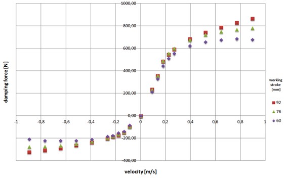
The achieved procedure allows for the recording of parametric absorber damping properties set within a certain range of variation extortion. The strong dependence of the damping characteristics for the working stroke length determines the need to take account of this phenomenon in computational models of automotive shock absorbers. The relationship describing this phenomenon in general is as follows:
where: v – the current velocity of extortion, ws – the total length of the working stroke.
The study has also helped to determine the relationship describing the stiffness of the damper. For this purpose, an experiment was planned. The working characteristics of shock absorber was measured for different frequency with different working strokes. For each test was combination of stroke length and frequency of extortion were read chart of the forces that were generated by the shock absorber for zero motion velocity. Sample results are presented in Fig. 5.
Fig. 5The characteristics of stiffness of damper obtained for different frequencies of extortion
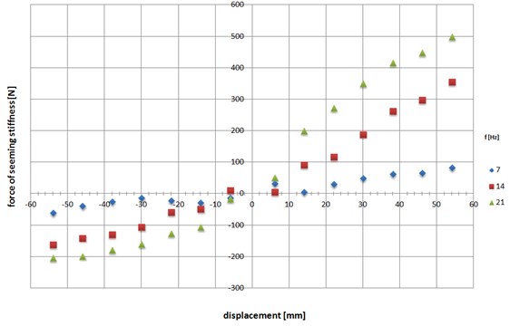
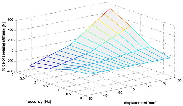
Characteristics of the resulting damper stiffness is a function of frequency and displacement. Thus the resulting damper stiffness can be described as:
where: d – displacement, f – frequency of the cyclic load.
The effect of changing of frequency for dampers is very significant. Twice a change in the frequency of working strokes absorber gives results in almost 50 % increase in force resulting from the elastic properties of the shock absorber. It should be noted that the phenomenon of the resulting damper stiffness produces almost zero values for frequencies less than 0.5 Hz.
4. The visco-elastic model of the vibration damper
Consideration of dependencies described in Eqs. (2) and (3) allows to introduce the vibration damper model as a pair of graphs surface (Figs. 6 and 7). These can be likened to a map of operation of shock absorber.
Determination of instantaneous values of damping forces and the resulting damper stiffness is based on such models set by interpolation. For the approximation of the damping function at points other than nodes of the interpolant, the estimation error of the approximation can be calculated. For this purpose function F(x) (called the interpolant) should be found, which in the nodes of interpolation has the same values as the function y=f(x).
Interpolation is in a sense opposite to the tabulation task of functions. With the analytical form of the function build an array of values, interpolation based on an array of functions was define in analytical form. The proper algorithm for the determination of the values of the damping forces and the resulting damper stiffness is based on the interpolation of two-arguments function using the theory of spline functions.
Fig. 6The surface of damping force
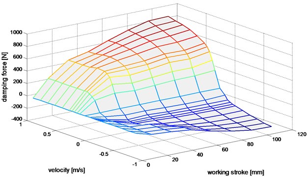
Fig. 7The distribution of experimental damper force illustrating the resulting damper stiffness effect
The value of damping force FD in the concept model of shock absorber can be determined by interpolation:
where: limits a, b, c and d are determined empirically.
The approximation of function values FD for any arguments:
it is made for the known values – interpolation nodes which are the results of measurements:
where: a≤v0≤v1≤v2≤…≤vn≤b, c≤w0≤w1≤w2≤…≤wm≤d using a spline functions.
The force of the resulting damper stiffness Fss reads:
where: limits a, b, c and d are determined by experimental approximation of function Fss:
for interpolation nodes:
where: a≤d0≤d1≤d2≤…≤dn≤b, c≤f0≤f1≤f2≤…≤fm≤d.
The strong dependence of the damping characteristics on the two variables is clearly visible in Fig. 4. This is a decisive prerequisite for testing new solutions. Note that not only velocity but also the working stroke length are important in this approximation. Similarly, when in operation, examining the condition of the shock absorber it can’t be uniquely determined for changing the length of the working stroke. Exactly such a situation occurs during testing of automotive shock absorbers on stand of EUSAMA or BOGE carried out taking in different frequency domains.
The second factor influencing the working of shock absorber is the resulting damper stiffness (Fig. 5). Damper does not convey static, but with dynamic force its operation resembles the action of the spring. Furthermore, the stiffness coefficient is not constant and increases with increasing frequency of the cyclic load. Thus, dynamic damper tests should be carried out taking into account the frequency domains.
5. Conclusions
The obtained results of the model of the shock absorber give a definite proof that the resulting damper stiffness is an important factor which cannot be neglected at higher frequencies of cyclic load. The model, to some extent, demonstrates the solution of the problem, which is the correct choice of the degree of simplification. This allows to define a more reliable measure of the technical condition of the whole suspension system.
The situation is similar in the case of prototyping new shock absorber design solutions. Finding the right amount of design parameters such as the cross-sectional area of calibrated holes and overflow valve characteristics limiting the maximum force generated in the damper should be carried out taking into account characteristics of damping and the resulting damper stiffness. The computational model of the dynamic damper, based on the two functions of two arguments is a definite objective of future research.
References
-
Konieczny Ł.,Burdzik R., Figlus T. The possibility to control and adjust the suspensions of vehicles. Activities of Transport Telematics, Springer, CCIS, Vol. 395, p. 378-383.
-
Burdzik R., Konieczny Ł. Vibration issues in passengers car. Transport Problems, Vol. 9, Issue 3, 2014, p. 83-90.
-
Pankiewicz J., Homik W. Examinations of torsional vibration dampers used in reciprocating internal combustion engines. Polish Journal of Environmental Studies, Vol. 20, Issue 5A, 2011, p. 108-111.
-
Wierzbicki S. Laboratory control and measurement system of a dual-fuel compression ignition combustion engine operating in a cogeneration system. Solid State Phenomena, Vol. 210, 2014, p. 200-205.
-
Kłaczyński M., Wszołek T. Detection and classification of selected noise sources in long-term acoustic climate monitoring. Acta Physica Polonica A, Vol. 121, Issue 1A, 2012, p. 179-182.
-
Burdzik R., Węgrzyn T., Konieczny Ł., Lisiecki A. Research on influence of fatigue metal damage of the inner race of bearing on vibration in different frequencies. Archives of Metallurgy and Materials, Vol. 59, Issue 4, 2014, p. 1281-1287.
-
Pankiewicz J., Deuszkiewicz P., Dziurdź J., Zawisza M. Modeling of powertrain system dynamic behavior with torsional vibration damper. Advanced Materials Research, Vol. 1036, 2014, p. 586-591.
-
Dąbrowski D., Batko W., Cioch W. Model of the gears based on multibody system and its validation by application of non-contact methods. Acta Physica Polonica A, Vol. 123, Issue 6, 2013, p. 1016-1019.
-
Dąbrowski Z., Dziurdź J., Klekot G. Studies on propagation of vibroacoustic energy and its influence on structure vibration in a large-size object. Archives of Acoustics, Vol. 32, Issue 2, 2007, p. 231-240.
-
Dixon C. J. The Schock Absorber Handbook. John Wiley and Sons, Ltd., 2007.
-
Warczek J. Application of time shift for nonlinear damping characteristic identification. Transport Problems, Vol. 4, Issue 3, 2009, p. 91-96.
-
Warczek J., Burdzik R., Peruń G. The method for identification of damping coefficient of the trucks suspension. Key Engineering Materials, Vol. 588, 2014, p. 281-289.
-
Burdzik R. Implementation of multidimensional identification of signal characteristics in the analysis of vibration properties of an automotive vehicle’s floor panel. Eksploatacja i Niezawodność – Maintenance and Reliability, Vol. 16, Issue 3, 2014, p. 439-445.
-
Siergiejczyk M., Paś J., Rosiński A. Evaluation of safety of highway CCTV system’s maintenance process. Communications in Computer and Information Science, Vol. 471, 2014, p. 69-79.
-
Wierzbicki S., Śmieja M. Visualization of the parameters and changes of signals controlling the operation of common rail injectors. Solid State Phenomena. Mechatronic Systems, Mechanics and Materials II, Vol. 210, 2014, p. 136-141.
-
Oleksiak B., Kozioł M., Wieczorek J., Krupa M., Folęga P. Strength of briquettes made of cu concentrate and carbon-bearing materials. Metalurgija, Vol. 54, Issue 1, 2014, p. 95-97.
-
Oleksiak B., Siwiec G., Blacha-Grzechnik A., Wieczorek J. The obtained of concentrates containing precious metals for pyrometallurgical processing. Metalurgija, Vol. 53 Issue 4, 2014, p. 605-608.
-
Oleksiak B., Łabaj J., Wieczorek J., Blacha-Grzechnik A., Burdzik R. Surface tension of cu-bi alloys and wettability in a liquid alloy – refractory material – gaseous phase system. Archives of Metallurgy and Materials, Vol. 59, Issue 1, 2014, p. 281-285.
-
Myszka D., Wieczorek A. An assessment of the applicability of austempered ductile iron containing Mo and Ni for mining machines parts. Archives of Metallurgy and Materials, Vol. 58, Issue 3, 2014, p. 967-970.
-
Ragulskis K., Kanapeckas K., Jonušas R., Juzėnas K. Applications of torsional vibrations for vibro-driling operations. Mechanika, Vol. 17, Issue 5, 2011, p. 498-502.
-
Worden K., Hickey D., Haroon M., Adams D. Nonlinear system identification of automotive dampers: a time and frequency-domain analysis. Mechanical Systems and Signal Processing, Vol. 23, 2009.
-
Konieczny Ł., Burdzik R. Comparison of characteristics of the components used in mechanical and non-conventional automotive suspensions. Mechatronic Systems, Mechanics and Materials II, Solid State Phenomena, Vol. 210, 2014, p. 26-31.
-
Warczek J., Burdzik R., Konieczny Ł. The concept of multi-parametric diagnostic model of car shock absorber. Diagnostics of Machines, XXXVII Symposium, Faculty of Transport Silesian University of Technology, 2010.
-
Warczek J., Burdzik R. Visco-elastic model of dynamic of hydraulic damper as a basis for determining the measurement condition. Scientific Papers of Transport. Silesian University of Technology, Issue 66, 2010.
-
Gardulski J., Warczek J. Identification of damping characteristic example suspension of car the hydro-pneumatic construction. Diagnostic, Vol. 3, 2009, p. 41-44.
