Abstract
We investigated a high damping rubber bearing (HDRB) that mitigates damage to buildings and bridges from earthquakes. An HDRB can bear large loads for long periods of time and is capable of large deformations during an earthquake. The characteristics of the HDRB considered in this research include a very high damping capacity, with an equivalent damping factor of more than 15 % for a large earthquake. Moreover, we examined various dependency properties such as compressive stress, frequency, and repeated loading. To evaluate seismic isolation with an HDRB on several earthquake waves, we performed a shaking table test. In this test, deck acceleration was measured by accelerometers. Shear forces on piers were surveyed by using load cells. Furthermore, the seismic capacity of an isolated system with an HDRB was compared with a non-isolated system through shaking table tests. The results show that deck acceleration and shear force were relatively reduced by the HDRB.
1. Introduction
Structures are becoming larger in scale, and there is a growing need for specialized structures such as nuclear plants and LNG storage tanks. In particular, with a growing demand for long span bridges such as cable-stayed bridges and suspension bridges, design technologies have been developed to secure the stability and usability of such structures (Jeong Kil-Yeong et al., 2002) [1]. In this regard, the seismic isolation system has been adopted, which is a passive control technique to reduce vibration in structures. In other countries, the system is widely used to minimize the damage to large-scale structures (including buildings, bridges, and nuclear plants) from dynamic loading such as an earthquake. Since a seismic isolation system has relatively high economic feasibility and efficiency, research has been actively conducted, mainly in technologically advanced countries (Kelly, 1986, 1999) [2, 3]. These countries, including Japan, have constructed many bridges and buildings using seismic isolation equipment, and the constructed structures have proved their stability with an effective seismic capacity in actual earthquakes. Particularly, the U.S. and Japan have been actively researching seismic isolation systems of the structures with the seismic isolation equipment and been using the standards on design and verification methods. Although research and development on seismic isolation equipment is gradually increasing in Korea, currently there are no established standards on seismic isolation design using seismic isolation equipment, design processes, and experimental evaluation standards. There are a growing number of studies and applications of seismic isolation equipment to ensure effective seismic design for bridges in Korea (Oh Ju et al., 2009) [4]. With increasing interest in the usability of structures, seismic isolation equipment has been widely used to minimize the damage to structures from earthquakes. Most of the studies and applications have used the lead rubber bearing (LRB) approach, and there is growing concern for the high damping rubber bearing (HDRB) that is unnecessary to insert extra lead because of the damping force in the rubber itself. A HDRB is a laminated rubber bearing that uses specialized high damping rubber (HDR) with the capacity to absorb energy as it transforms itself due to external energy sources such as earthquakes, as the same rubber bearing as the lead rubber bearing and the seismic isolation equipment with damping function [3]. The hysteretic characteristics of an HDRB can be changed by changing its rubber composites, and it has the disadvantage that the damping function, as energy dissipation capacity, is slightly lower than that of a lead rubber bearing (1997) [5]. However, it can exert outstanding damping force compared to most similar natural rubber bearing materials and shapes (2002) [6]. Fig. 1 shows the shape of an HDRB and its schematic model. The HDRB is modeled in the form of a spring element, friction damping element, and viscous damping element that are dynamically connected in parallel. We examined the seismic isolation performance of bridges with HDRBs, as shown in Fig. 1(a). The dynamic interpretation model of an HDRB is shown in Fig. 1(b). Before performing a shaking table test, we examined the basic characteristics of the HDRB through a characteristics test using a miniature specimen. After conducting the test, were viewed the properties of the actual seismic response of seismically-isolated bridges and analyzed the reduction effect of the seismic response. The incident seismic wave used in the shaking table test was based on the records of earthquake waves that actually occurred in other countries.
Fig. 1An HDRB
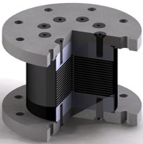
a) Shape of HDRB
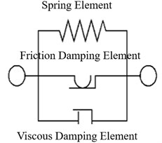
b) Dynamic interpretation model
2. Characteristics test of seismic isolation bearing
A characteristics test was conducted to identify the basic characteristics of the device. A compression test and shear test were performed to determine the characteristics needed to design seismic isolation equipment including the basics, compression stiffness, shear stiffness, and damping ratio.
2.1. Specifications of fatigue tester
The tester used for the characteristics test of the HDRB specimens is a 2000 kN compression-shear fatigue tester as shown in Table 1 and Fig. 2.
Table 1Specifications of compression-shear fatigue tester
Category | Maximum load (kN) | Maximum displacement (mm) | Maximum speed (mm/s) |
Vertical capacity | ±2000 | ±100 | ±100 |
Horizontal capacity | ±500 | ±200 | ±250 |
2.2. Design and production of HDRB device
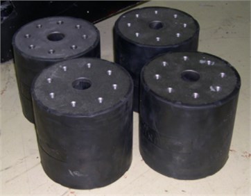
HDRB device is a kind of seismic isolation equipment, designed and manufactured to evaluate the characteristics of bearing and seismic isolation performance. In designing the specimen, it is necessary to estimate the stiffness of the seismic isolation equipment first, estimate the thickness of the rubber and steel back-up plate, and calculate the effective stiffness and vertical stiffness (ISO 22762, 2005) [7]. Table 2 shows the design conditions of the HDRB produced for the shaking table test. Fig. 3 shows the cross section specifications and actual shape of the device.
Fig. 22000 KN compression-shear fatigue tester
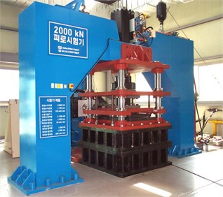
Table 2Specimen design conditions
Characteristics | Value |
Shear factor of rubber (G) | 0.7 MPa |
Yield strength of steel shim plate (fy) | 240 MPa |
Design displacement (∆) | 19.3 mm |
Effective period (T) | 0.69 s |
Primary shape factor (S1) | 15.3 |
Secondary shape factor (S2) | 1.9 |
S1 is the primary shape factor ((Ds-Dh)/4ti), S2 the secondary shape factor (Ds/nti) Ds is the diameter of internal steel plate, Dh is internal hole ti is the thickness of one layer of rubber, n is the number of rubber layers | |
Fig. 3Specifications and shape of HDRB
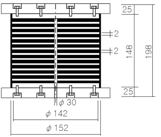
a) Cross-section specifications
b) HDRB specimens used in experiment
2.3. Compression characteristics test
Before performing theshaking table test on the seismic isolation equipment, weconducted acompression and shear characteristics test to review the characteristics of the miniature specimen. To obtain the vertical stiffness of the HDRB device, the test was conducted after installing a displacement transducer at room temperature. The compression stiffness was 912 kN/mm as indicated in Table 3, which satisfied the evaluation standard of ±30 % with a margin of error of about 5 % compared to the design value.
Table 3Design conditions of specimen
Compression stiffness (kN/mm) | |||
Design value | Experimental value | Standard | Margin of error |
965 | 912 | ±30 % | –5 % |
2.4. Shear characteristics test
2.4.1. Shear strain dependency test
To identify the changes in shear stiffness and equivalent damping ratio according to the shear strain of the HDRB, a compression-shear characteristics test was conducted with various values of shear displacement. For loading displacement, the test was conducted with shear strains of 10 %, 20 %, 50 %, 100 %, and 150 %. The test results are shown in Fig. 4. The shear stiffness decreased by about 56 % as the shear strain increased. In addition, the equivalent damping ratio decreased by about 16 % with an increase in loading displacement.
2.4.2. Frequency dependency test
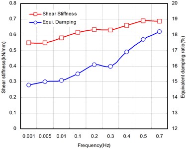
To understand the changes in shear stiffness and equivalent damping of the HDRB under changes in frequency, a compression-shear characteristics test was conducted by changing the frequency. In the test, we applied a vertical load to consistently maintain the design surface pressure at room temperature for nine frequencies: 0.001, 0.005, 0.01, 0.1, 0.2, 0.3, 0.4, 0.5, and 0.7 Hz. As a result, the shear stiffness and equivalent damping ratio each increased by 23 % with an increase in frequency. Fig. 5 shows the changes in shear stiffness and equivalent damping ratio according to the changes in frequency.
Fig. 4Shear strain dependency test results
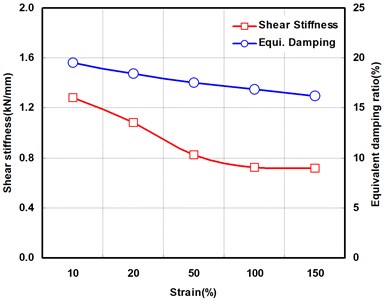
Fig. 5Frequency dependency test results
2.4.3. Compressive stress dependency test
To review the dependency characteristics according to the compressive stress of the specimen, a compression-shear characteristics test was conducted with various levels of compressive stress. In the test, vertical loads were applied to maintain the design surface pressure at room temperature. A sine wave of 0.5 Hz was repeatedly loaded 11 times to generate the design shear displacement. The test was conducted at 0 %, 50 %, 100 %, 150 %, and 200 % of the design surface pressure. According to the results, the equivalent damping ratio increased as the surface pressure increased. The high surface pressure dependency occurred because of the increase in viscous and friction damping elements between rubber molecules as the surface pressure rose. Fig. 6 shows the changes in the equivalent damping ratio due to surface pressure.
2.4.4. Repeated loading dependency test
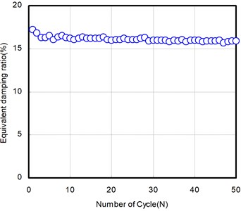
We applied repeated loads on the HDRB specimen in order to determine the subsequent changes in shear stiffness and the equivalent damping ratio. By consistently applying the vertical load to maintain a constant design surface pressure at room temperature, the load of test was applied 50 times in order to generate the relevant design shear displacement. As a result, the shear stiffness changed significantly about three times more than initial as shown in Fig. 7. However, the dynamic range gradually decreased during the repeated loading after the third loading. Comparison with the shear characteristics of the 1st and 50th time, the shear stiffness dropped by 12 % and equivalent damping ratio dropped by 5 %. In addition, as a result of the shear characteristics test after lowering the temperature of the same specimen to the initial temperature after the repeated test, the shear stiffness and equivalent damping ratio decreased by 4 % and 2 %, respectively, compared to the initial value of the repeated test. The result indicates that they were affected by the change in temperature.
Fig. 6Compressive stress dependency test results
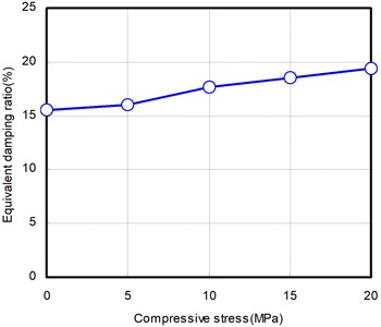
Fig. 7Repeated loading dependency test results
3. Shaking table test of miniature bridge model
3.1. Shaking table test model
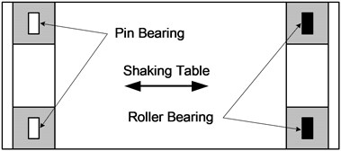
The miniature bridge model for the shaking table test was constructed by scaling down the actual bridge by 1/5 according to the similarity ratio. The key variable in the seismic behavior of bridges, acceleration, became similar to 1/1 and time and length was each applied with section given the limit to the shaking table performance. The gross weight of the upper structure of the bridge is about 12.74 MN and that of the miniature bridge is 101.9 KN. The bridge piers of the model are composed of two box-type steel columns. We used a lead block for additional self-load to adjust the self-load of the deck to the similarity ratio. The scaling standard used the dynamic characteristics of the actual bridge and miniature model. The determined similarity ratio for similar dynamic characteristics is shown in Table 4. The shape of the miniature bridge installed on the shaking table is shown in Figs. 8 and 9, and the seismic isolation bearing was installed as shown in Fig. 10.
Table 4Similarity ratio applied to bridge specimen
Parameter | Scale factor | Model/prototype |
Length | L | 1/5 |
Time | √L | 1/√5 |
Mass | L3 | 1/125 |
Displacement | L | 1/5 |
Acceleration | 1 | 1/1 |
Stress | L | 1/5 |
Strain | 1 | 1/1 |
Force | L3 | 1/125 |
Horizontal stiffness | L2 | 1/25 |
Fig. 8Miniature bridge installed on the shaking table
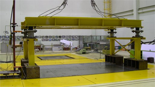
Fig. 9Cross-section of miniature bridge
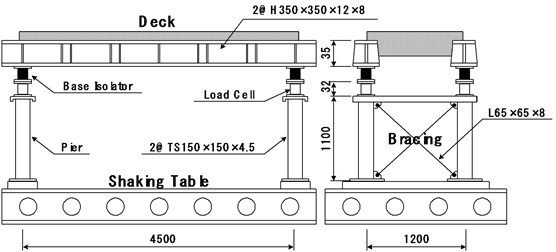
Fig. 10Installation of bearing equipment
a) Non-isolated
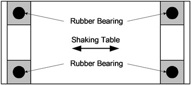
b) Isolated (HDRB)
3.2. Test method
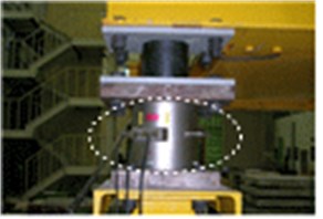
In the shaking table test, the data measuring targets were power, displacement, and acceleration. To measure the data, a load cell was installed in two areas of the bridge where the seismic isolation equipment was installed. Displacement transducers were installed in the basement, under the seismic isolation equipment, and on the upper part of the load cell. In addition, the accelerometers were each attached in the basement, at the center of the bottom, and on the deck with the seismic isolation equipment. Fig. 11 shows the installation of the equipment.
Table 5Installation location and quantity of attachment of measurement equipment
Measurement equipment | Location | Quantity |
Load cell | Pier top, HDRB bottom | 2 |
Displacement transducer | Base, load cell bottom and top | 3 |
Base, load cell top, HDRB top | ||
Accelerometer | Base, load cell top, deck center | 3 |
Base, load cell top, deck center |
Fig. 11Installation of measurement equipment for miniature bridge
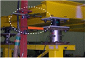
a) Displacement transducer (upper part)
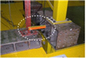
b) Displacement transducer(bottom part)
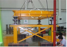
c) Accelerometer (deck)
d) Load cell (bottom part of the bearing)
3.3. Incident seismic load
For the shaking table test, we used six overseas seismic wave acceleration histories. including the El Centro earthquake, Taft earthquake, and Northridge earthquake, which occurred in California in the U.S.; the Hachinohe earthquake and Akita earthquake in Japan; and the Mexico City earthquake in Mexico. The incident seismic waves used in this experiment are shown in Table 6.
Table 6Incident earthquakes used in shaking table test
Earthquake | Record | Peak ground acceleration (PGA) |
Akita | Nihonkai Chubu, Japan, May 23, 1983 | 0.19 |
Component N-S | ||
El Centro | Imperial Valley, California, USA, May 18, 1940 | 0.34 |
Component S00E | ||
Hachinohe | Tokachi, Japan, May 16, 1968 | 0.23 |
Component N-S | ||
Mexico City | Mexico City, Mexico, September 19, 1985 | 0.17 |
Northridge | Sylmar, California, USA, January 27, 1994 | 0.34 |
Taft | Kern County, California, USA, July 21, 1952 | 0.16 |
Component N21E |
4. Test results and analysis
In order to conduct a comparative evaluation of the seismic isolation performance of the HDRB, we applied excitation based on actual seismic loads. The test model had the properties of maximum response acceleration of the deck and maximum shear force of bridge and relative displacement according to the seismic isolation equipment. Table 6 shows the reduction effect of seismic loads of seismic isolation bridges in comparison with non-isolated bridges.
4.1. Behavior of bridge deck
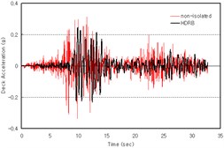
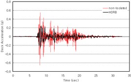
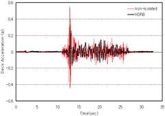
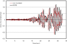
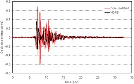
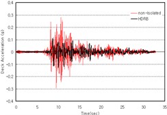
Table 7 and Fig. 12 show the maximum response accelerations of the bridge deck in comparison with shaking table test of miniature bridges after applying the HDRB seismic isolation equipment. The test of miniature bridges had a higher reduction rate. The HDRB had a relatively reliably high reduction rate, while the HDRB response to the earthquake in Mexico City had a reversely increasing reduction rate of response acceleration compared to the non-isolated equipment. In this regard, extra care is recommended when using seismic isolation equipment such as an HDRB on weak ground.
Table 7Comparison of shaking table test results
Earthquake | FGA (g) | Maximum response acceleration of deck (g) | Reduction rate (%) | Maximum shear force of bridge (KN) | Reduction rate (%) | Relevant displacement (mm) | Enhancement ratio | |||
(a) | (b) | (a) | (b) | (a) | (b) | |||||
Akita | 0.19 | 0.338 | 0.246 | 27.3 | 9.98 | 4.12 | 58.7 | 3.78 | 12.86 | 3.4 |
El Centro | 0.34 | 0.658 | 0.254 | 61.4 | 18.15 | 4.37 | 75.9 | 2.89 | 13.15 | 4.6 |
Hachinohe | 0.23 | 0.557 | 0.259 | 53.5 | 16.17 | 4.29 | 73.4 | 3.68 | 10.79 | 2.9 |
Mexico City | 0.17 | 0.233 | 0.243 | –0.04 | 6.18 | 4.20 | 32.0 | 2.63 | 14.43 | 5.5 |
Northridge | 0.34 | 0.685 | 0.358 | 47.7 | 19.55 | 5.77 | 70.4 | 2.75 | 19.39 | 7.1 |
Taft | 0.16 | 0.293 | 0.128 | 56.3 | 8.41 | 2.06 | 75.5 | 1.65 | 4.73 | 2.9 |
a) Non-isolated equipment, b) Equipment with HDRB | ||||||||||
Fig. 12Maximum response acceleration of bridge deck
a) Akita
b) El Centro
c) Hachinohe
d) Mexico City
e) Northridge
f) Taft
4.2. Behavior of bridge
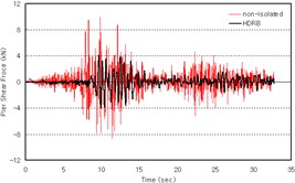
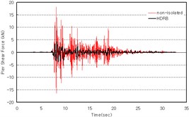
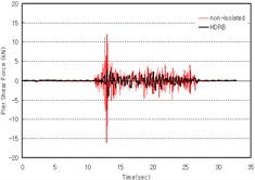
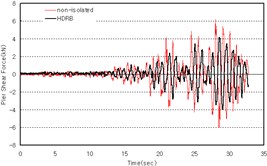
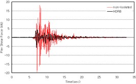
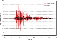
In terms of the shear force exerted on the bottom part of the bridge during several earthquakes, the seismic isolation equipment exhibited a higher rate of shear force reduction than the non-isolated equipment. Except for the earthquake in Mexico City, the seismic isolation equipment provided at least a 58 % reduction in rate compared to the non-isolated equipment. However, as to the earthquake in Mexico City with long-period seismic waves passing through the weak ground, the equipment with the HDRB had the maximum shear force reduced by about 32 % compared to the non-isolated equipment (Table 7). Fig. 13 shows a comparison of the shear force exerted on the bottom part of the bridge between the non-isolated and isolated equipment.
4.3. Change of seismic isolation equipment
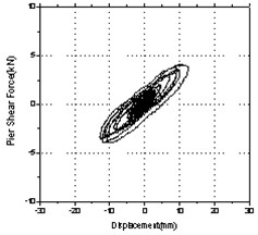
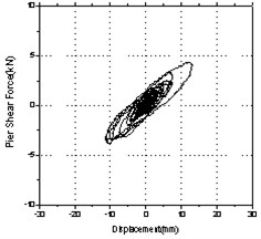
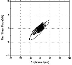
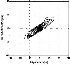
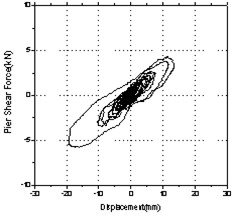
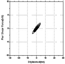
Table 7 shows a comparison of relative displacement from the shaking table test of the miniature bridges using the seismic isolation equipment. The test results show that the relative displacement of the bridge with the HDRB was higher than that of the non-isolated bridge. The bridge with the HDRB had a relative displacement that was 2.9 to 7.1 times greater than that of the non-isolated bridge. The displacement response of the seismic isolated bridge increased compared to the non-isolated bridges due to the long period. In particular, the displacement response with a seismic isolation period similar to that of the earthquake in Mexico City occurred on the weak ground and significantly increased compared to that of the non-isolated bridges. Fig. 14 shows the hysteresis loop between the power and the displacement of the HDRB.
Fig. 13Shear force of the bottom part of the bridge
a) Akita
b) El Centro
c) Hachinohe
d) Mexico City
e) Northridge
f) Taft
Fig. 14Power-displacement hysteresis loop of HDRB
a) Akita
b) El Centro
c) Hachinohe
d) Mexico City
e) Northridge
f) Taft
4.4. Characteristics analysis of bridge behavior resulting from seismic wave
We analyzed bridge behavior characteristics under the seismic isolation design through the shaking table test with the miniature bridge and HDRB, and compared and analyzed the response acceleration of the deck, the shear force of the bottom part of the bridge, and the change in the bearing. In terms of the response acceleration of the deck and shear force of the bottom part of the bridge, the HDRB was relatively stable, with a relatively higher energy reduction rate in strong and weak earthquakes. On the other hand, the earthquake in Mexico City was a seismic wave with a significantly long predominant period compared to other historical earthquakes. According to the test results, by using the HDRB, the acceleration of the deck and the shear force of the bridge was quite amplified. In particular, the maximum response acceleration of the deck amplified about five times more than the earthquake in Mexico City and Taft earthquake is similar to peak ground acceleration (PGA). This occurred for several reasons, including the effect of the ground environment and the natural period.
First, the ground in Mexico City is weak, so the ground environment is unstable when the ground is disturbed. Thus, structures with seismic isolation equipment on weak disturbed ground often have amplified seismic motion in the frequency area due to the weak ground. In this case, since the amplified seismic isolation structure with an amplified effective frequency cannot play its role and thus the response of the structure can increase, it is necessary to be careful when installing the seismic isolation equipment. In addition, we note that the seismic response can be significantly amplified due to the coincidental resonance between the natural frequency of the seismic wave of Mexico City and that of the specimen structure. The section on seismic deign in the highway bridge design standard (2005) [8] described how the response may be somewhat amplified. When the natural period is long with a high height of the weak ground or bridges, seismic isolation design is not recommended. Thus, it is necessary to consider the use of the seismic isolation equipment in this environment more carefully.
5. Conclusions
A new seismic isolation system is required due to growing domestic and international interest in earthquake safety, and social demand for improved seismic design. Existing structures are designed and constructed under previous seismic design standards. We conducted a basic characteristics test on an HDRB and a shaking table test using a miniature bridge model. The test results were analyzed to evaluate the seismic capacity. The results are summarized as follows:
1) The equivalent damping ratio of the HDRB has a relatively high dependency on frequency and surface pressure, and a low dependency on shear strain. We recognize that such a high frequency and surface pressure dependency of the equivalent damping ratio is due to the influence of the special composite drug applied to the HDR on viscous and friction damping elements between the rubber molecules. The shear stiffness has a very high dependence on shear strain with a small dependence on surface pressure. Therefore, it is necessary to consider shear strain in designing the shear stiffness of an HDRB.
2) A shaking table test using several incident seismic waves was used to identify the outstanding damping capacity of maximum response acceleration delivered from the upper part to the deck of the seismic isolated bridge with the HDRB. The seismic isolated bridge with the HDRB had an outstanding dissipation capacity; thus, the shear force applied to the bridge was stable and significantly reduced compared to the non-isolated bridge.
3) The Mexico City earthquake, with its unusual results in the shaking table test, was a seismic wave with a long predominant period compared to other earthquakes. According to the test results, the acceleration of the seismic isolated bridge was strongly amplified. Such an earthquake is unusual and occurred on weak ground, so that it is hard to commonly see in the ground conditions of South Korea. However, we suggest that it is necessary to consider the period and ground motion conditions in designing seismic isolation using an HDRB.
References
-
Jeong Gil-yeong, Ha Dong-ho, Park Geon-rok, Gwon Hyeong-oh Experimental study on characteristics of low hardness rubber bearing. Journal of the Earthquake Engineering Society of Korea. Vol. 6, Issue 4, 2002, p. 39-49.
-
Kelly J. M. A seismic base isolation: review and bibliography. Soil dynamics and Earthquake Engineering, Vol. 5, 1986, p. 202-216.
-
Kelly J. M. Analysis of fiber-reinforced elastomeric isolators. Journal of Seismology and Earthquake Engineering (JSEE), Vol. 2, Issue 1, 1999, p. 19-34.
-
Oh Ju, Park Jin-yeong, Park Geon-rok, Kim Ssi-dong, Park Seong-kyu An experimental research on the characteristics of long term creep of HDRB. Journal of Earthquake Engineering Society of Korea, Vol. 13, Issue 1, 2009, p. 53-60.
-
Mineoh Takayama Road to 4 Seconds Seismic Isolation – Seismic Isolation Structure Design Manual. The Science and Engineering Books, 1997.
-
Earthquake structure. Introduction. The isolation structure Association of Japan, Ohmsa, 2002.
-
Iso22762. Elastomeric Seismic Protection Isolators Part 1: Test Methods, 2005.
-
Iso22762. Elastomeric Seismic Protection Isolators Part 2: Applications for bridges, 2005.
Cited by
About this article
This research was supported by Yeungnam University Research Grant in 2016.

