Abstract
Overhead travelling cranes work with intermittent motion, and therefore are most exposed to dynamic loads. In steel constructions, as a result of load pick up from the ground, vibrations of various degrees of intensity are induced, which should be included in crane design. These loads affect both the hoisting mechanisms and load-carrying structures. The aim of this study is the formulation of a phenomenological model of an overhead travelling crane enabling the identification of dynamic factors caused by lifting the load off the ground. The object of the study was 107 overhead travelling cranes with lifting capacities from 5 to 50 tones, designed in the Centre for Research and Development of Cranes and Transport Equipment “Detrans” in Bytom and produced in Poland in the period 1970-2005. Cranes were classified according to the stiffness classes proposed in European standards for crane safety. In this paper, computer simulations are carried out on the basis of a phenomenological model with four degrees of freedom, three of them corresponding to the crane’s structure and one to the hoisted load. The model also allows assumption of the variable stiffness and damping of the steel rope during its shortening. The values of the dynamic factors refer to the various design and dynamic parameters of overhead travelling cranes, formulating appropriate conclusions.
1. Introduction
Nowadays, currently designed overhead travelling cranes are characterized by their simple and modular construction, thus all kinds of modernization and repairs may be carried out efficiently and effectively. The development of electronics, in particular of automatic regulation systems, has enabled the non-degree regulation of angular velocities in electrical engines used in the drive systems of transport machines. Operating mechanisms applied in cranes must demonstrate an appropriate effective power. Substantial effective power used in crane drives causes precipitation of the working machine from the equilibrium state. Flexibility of the crane structure causes induced dynamic loads usually to take the form of mechanical vibrations. Mechanical vibrations of the crane structure, induced by the winch drives of the cranes and the hoistings, are characterized by smaller oscillation amplitudes lasting longer than vibrations caused by the hoisting gear.
Overhead travelling cranes are basic working machines used during reloading in a limited space. The work of the crane drives and mechanisms often generates an intermittent motion, which causes induction of the dynamic loads [1, 2]. Numerical identification of the dynamic load, carried out theoretically, enables cranes to be designed safely in accordance with European norms [3]. The safety of transport machines, formulated in European Union directives, imposes specified requirements on producers with respect to design, performance and operation. This applies in the first instance to internal transport machines, which are the subject of continuous supervision. The design process with respect to steel structures is currently highly normalized and applies more accurate calculation methods. Research into a crane model, in terms of identification of the dynamic factors (dynamic force surplus), which is correctly conducted enables the design of machines characterized by increased strength, reliability and durability.
Determining the dynamic factor values, which are caused by non-steady states, is usually undertaken by computer simulation. The main benefit arising from researching the model, the cost of which is lower than the cost of research carried out on real objects, is the cost reduction. The basis for such simulations is formulation of an appropriate phenomenological model. The phenomenological model is the starting point in deriving cause–effect relationships. The literature, presents a variety of classes of phenomenological models, which, to a different degree and with different precision, map the real operating conditions of overhead travelling cranes [1, 4-6].
One of the most important loads that should be taken into account due to the norms of the European Union is the force caused by inertial and gravity effects acting vertically on the hoist load. Assuming that the initial phase of compensation of a relaxed rope is omitted, load hoisting from the ground is done in two stages. In the first stage, hoisting ropes are stretching, while the crane structure undergoes an initial deflection. In the case of hoisting an unrestrained grounded load, the load-carrying crane structure comes into natural frequency vibration in the second stage. In the first vibration cycle (with the highest amplitude) dynamic force due to hoisting an unrestrained grounded load will occur and the dynamic factor is the aim of the modelling process. The following paper presents the results of the identification of the dynamic factor in overhead travelling cranes, caused by hoisting an unrestrained grounded load.
2. Formulation of numerical model of hoisting an unrestrained grounded load
Construction of the phenomenological model is preceded by simplification of the object of study and the phenomena occurring within. At this stage of the research the range of model simplifications is also set. Model studies so far conducted indicate that in many cases steel structures may be mapped by an appropriate one-mass model [1, 2]. Inclusion of load mass and the flexibility of the rope results in a dynamic system with two degrees of freedom. The phenomenological model formulated in such a way is the simplest one that can be adapted to the numerical identification of the dynamic factor φ2 of a working machine hoisting an unrestrained grounded load. Nonetheless, assumption of such a simplified model may not reflect the real values of dynamic surpluses. Computer simulations of overhead travelling cranes, mapped by models with different numbers of degrees of freedom, show that the more degrees of freedom that are taken into account, the more precise the numerical calculations. Increased precision in the calculations is visible during the determination of the resonance frequencies.
Fig. 1Phenomenological model of overhead travelling crane
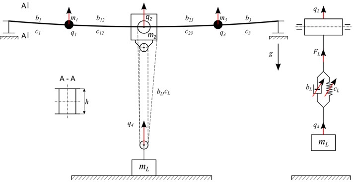
In this paper, computer simulations are carried out on the basis of the phenomenological model with four degrees of freedom (Fig. 1), where qi are the generalized coordinates. In order to formulate the model, the following assumptions are made. The crane is mapped by a system of lumped masses: m1, m2, m3, which are connected by elastic elements: c1, c12, c23, c3 and damping elements: b1, b12, b23, b3. The elastic-damping properties of the crane components are described by the Kelvin-Voigt model. The Influence of the buffer beams’ flexibility is omitted due to their higher stiffness with respect to girder stiffness. It is assumed that vibrational coupling between the crane’s girders does not occur. A system of pulley blocks reduces the nonlinear elastic-damping element described by physical parameters: cL and bL. Variable rope stiffness and damping [7], coming from its shortening, are taken into account. It is also assumed that load pick-up from the ground takes place when the hoist drive engine achieves its nominal velocity.
Differential equations of the motion of the overhead travelling crane model (Fig. 1) may be derived by a variety of methods. At the current stage of development of computer technology, the engineer has access to software (Matlab, Mathematica, Maple…) which automatically generate differential equations of motion. It is exemplary that, in order to derive the explicit form of the mathematical model of the auxiliary dynamic system in Mathematica software, it is enough to set the dependencies for the potential and kinematic energy, Reyleigh function and constraint equations. As a result of this approach to model research, the mathematical model of the overhead travelling crane in the following form is obtained:
Relationship of the force change within the rope is given by:
where: vB – is rope speed when reeling on the rope drum; iWK – pulley block ratio, mL – hoist load mass, g – gravitational acceleration.
In the mathematical model, additional parameters controlling simulation Si are applied. Control variable S1 defines the time moment t0 in which the load is being picked up from the ground, while a control variable S2 models the force increase in the lifting ropes. Variable S2 is a meaningful parameter, because it has decisive impact on the identification of the dynamic factor values. In preliminary computer simulations, it is assumed that the force in the rope increases according to the unit step signal. Such an assumption results in excessive values of the dynamic factors, which are caused by the immediate occurrence of a nominal load on the rope. Bearing in mind the above remarks, it is necessary to include time τ in the calculations, at which the force in the rope reaches the nominal value [2, 8]:
where: qM – maximal static deflection caused by own weight, measured in the centre span of the crane’s structure, qL – static rope elongation caused by lifted load, vP – speed of load pick-up from the ground.
The inclusion of the tensioning of the rope strands significantly gives credence to the results of identification. An important phase in model research is the estimation of the mathematical model coefficients, Eq. (1). Identification of alternative lumped masses mi and structure stiffness is quite easy. Those parameters can be estimated on the basis of the relationships resulting from the forces method or rigid finite elements method [9, 10]. However, it is much harder to identify elements dissipating energy. Knowledge about the damping properties of the steel construction of the crane and rope is essential to analyse issues of positioning of the load and determining the time of the diminution in mechanical vibrations. The dissipation properties of the crane’s girders were calculated according to [2, 11, 12], where the damping logarithmic decrement values for welded box girders are given by Eq. (4):
From Eq. (4) it is possible to estimate the dissipation properties of the girders using only the height h and length L of a girder. In order to effectively identify the dissipation properties of the girders, figures from Eq. (4) are approximated by a linear function. As a result, the general logarithmic equation of the damping decrement [13, 14] with all possible combinations of ratio h/L is obtained:
Based on the numerical values of a logarithmic damping decrement, substitute mass and the stiffness of a load-carrying crane structure, it is possible to determine the substitute damping factor of a welded girder with closed box cross-section:
Physical values characterizing the lifting rope are identified by [15]:
where: A – the metallic cross sectional area of rope, l0 – initial length of rope, E – Young’s modulus of the material from which the rope is made, ς – dimensionless damping coefficient of the rope, mlin – rope mass with hook block mass.
The value of the dimensionless damping coefficient of the steel ropes ς= 0.07 is taken from paper [16]. The relationships given by Eqs. (1)-(7) refer to the dynamics of the mechanical subsystem. In the case of identification of the dynamic factor, it is necessary to include the kinematic characteristics of the drive system of the hoisting mechanism. The kinematic characteristics of the drive system of the hoisting mechanism map the velocity of winding a rope on a drum. The winding velocity directly defines the velocity of the lifted load. For computer simulation, winding velocity is modelled by a differential equation of the first order:
Such a mapping of the winding velocity corresponds to the HD1 class of drive system of the lifting mechanism according to [3], which cannot work with so called creep speed. In Eq. (8), the coefficient tM is interpreted as the time constant of the hoisting mechanism, while iWK represents the pulley block ratio. Control variable S3 defines the moment in which the drive of the hoisting mechanism starts to work. As a result of the load pick-up from the ground, in steel construction vibrations of various degrees of intensity are induced, which should be included in crane design. Assessment of the intensity of the dynamic phenomena induced at the moment in time of load pick-up may be made based on the dynamic factor given by:
The presented analytical relationships provide a formal basis for computer simulation in a range identifying the dynamic surplus factor φ2-1 caused by lifting the load off the ground.
3. Model research
The object of the study was 107 overhead travelling cranes with lifting capacities from 5 to 50 tones, designed in the Centre for Research and Development of Cranes and Transport Equipment “Detrans” in Bytom and produced in Poland in the period 1970-2005. In the first stage of the research, the The object of the study was 107 overhead travelling cranes with lifting capacities from 5 to 50 tones, designed in the Centre for Research and Development of Cranes and Transport Equipment “Detrans” in elastic properties of the cranes were classified with respect to stiffness classes HC according to [3]. Class HC1 includes flexible constructions, while class HC4 includes stiff constructions. European norms [3] unambiguously define criteria for specific classes. Generally, classification is carried out on the basis of the superposition of the maximal vertical displacement of the crane bridge qM and rope elongation qL, as an effect of maximal hoist load.
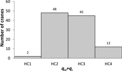
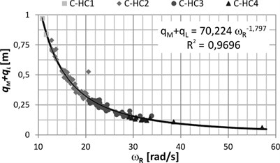
Fig. 2The results: a) the number of cranes in the various HC classes; b) the ratio of the parameter qM+qL to the resonance frequency of the crane ωR
a)
b)
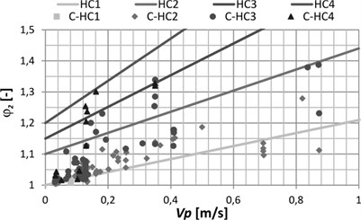
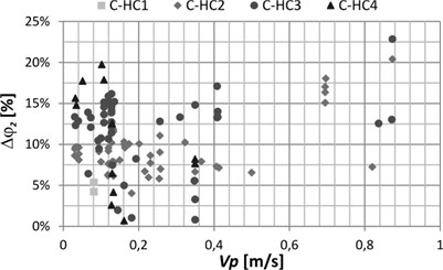
Fig. 3Results of numerical identification: a) dynamic factor φ2; b) relative error of dynamic factor φ2 identification
a)
b)
On the basis of the numerical calculations and statistical analyses, the cranes were assigned to appropriate HC classes (Fig. 2(a)). From classification of overhead bridge crane construction to a given HC class, it is possible to proceed if the lowest frequency of the transverse vibrations of the structure is known (Fig. 2(b)). European guidelines assume that the dynamic surplus factor φ2-1 includes the hoisting speed vP. In Fig. 3(a), the dynamic surplus factor to velocity function determined due to the norm [3] is marked by solid lines. The results of the computer simulation are mapped in Fig. 3(a) with markers and are called C-HC1 to C-HC4. The relative error from the numerical calculations is determined by reference to the dynamic surplus factor from the norm (Fig. 3(b)).
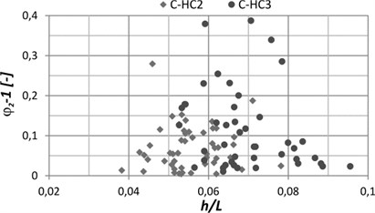
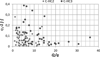
The distribution of the dynamic factors φ2 presented in Fig. 3(a) stems from not only the different hoisting speeds, but also variations in the construction features and dynamic properties. Therefore, further results of the numerical identification of the dynamic factors are presented as dependencies of the chosen geometrical mapping parameters, the kinematic and dynamic features of crane construction. Fig. 4(a) presents values of the dynamic surplus factor φ2-1 according to the dimensionless ratio of the girder height h and the crane bridge span L. Fig. 4(b) shows the relation between factor φ2-1 and the parameter defined as the ratio of hoisting capacity Q to the static deflection of the crane’s structure qM.
Fig. 4Results of the numerical identification of the dynamic factor due to: a) ratio of girder height to span of crane bridge; b) ratio of hoisting capacity to static deflection of the crane’s structure
a)
b)
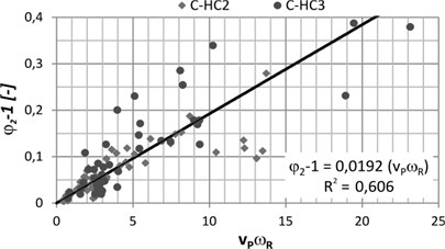
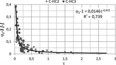
The chart in the Fig. 5(a) shows the distribution of the dynamic surplus factor as a function of the product of hoisting speed vp and the smallest resonance frequency of crane’s structure. To determine the parameter endearing the kinematic and dynamic crane features, the lowest harmonic vertical vibration should be considered, representing the resonant frequency of the crane. Fig. 5(b) presents the relation between the dynamic factor and the time of increasing the force in the rope.
In statistical analyses, cranes from classes HC2 and HC3 were included, while cranes classified as HC1 and HC4 were not taken into account due to there being too small a number to formulate final conclusions.
Fig. 5Results of the numerical identification of the dynamic factor due to: a) the product of the hoisting speed and the smallest resonance frequency of the crane; b) time of increasing the force in the rope
a)
b)
4. Conclusions
In this paper, the phenomenological model of an overhead travelling crane enabling identification of the dynamic factors caused by lifting the load off the ground was formulated. It is also worth mentioning that the model proposed in European Union norms [3] according to crane design has one degree of freedom. Designing the overhead travelling crane with use of such a simplified model disables reliable mapping of the working machine dynamics. Therefore, the numerical model applied in this research has four degrees of freedom, three of them corresponding to the crane’s structure and one to the hoisted load. The model also allows the assumption of variable stiffness and damping of the steel rope during its shortening. Such a model enables the inclusion of higher harmonics of the amplitude-frequency spectrum which have significant influence on working machine dynamics. The study, whose range covered the identification of dynamic factors, enabled the formulation of the following general conclusions:
1) During the identification of the dynamic factors, it is necessary to include the character and time for which the force in the rope reaches the nominal value. Assuming that increasing the force in the rope is described by the unit step function leads to significantly overstated values of the coefficient φ2. The unit step increase in the force may be taken into account in the research of breakdown models, that is, freezing to the ground or blocking the hoist load.
2) Parameter qM+qL, characterizing the elastic properties of a crane, may be identified with good approximation on the basis of the lowest resonance frequency of the vertical vibrations of the crane’s structure (Fig. 2(b)).
3) The formulated dynamic model of the overhead travelling crane maps the dynamic factors φ2 very well and their values are close to the data of the European norm. Only in a few cases did the calculation error exceed the value of 15 % (Fig. 3).
4) No statistically significant correlation of factor φ2-1 and parameters such as height h, span L, capacity Q and maximal crane deflection qM were found (Fig. 4).
5) The correlation of factor φ2-1 and parameters such as hoisting speed vP, the lowest resonance frequency ωR, and constant τ that determines the time for which force in the rope reaches the nominal value, were found to be statistically significant (Fig. 5).
The first from the above conclusions indicates the direction of future research. Furthermore, in a future research model, the influence of the drive system of the hoisting mechanism (and especially the electromechanical coupling) on the value of the dynamic factor should be included. The proposed phenomenological model is an original evaluation of the crane’s dynamic factor caused by lifting the load off the ground, while the research object’s idealization and applied control variables enable its use in engineering practice. Appropriate control functions allow research into the unsteady states, for example those originating in unexpected breakdowns. Moreover, the advantage of the proposed numerical model is its simplicity and effectiveness. It is meaningful in the case of the fast prototyping of cranes in situations where the designer has no possibility of performing time-consuming calculations with the use of, for example, the finite element method.
References
-
Borkowski W., Konopka S., Prochowski L. The Dynamics of Working Machines. WNT, Warsaw, 1996.
-
Piątkiewicz A., Sobolski R. Cranes. WNT, Warsaw, 1978.
-
EN 13001−2:2011. Crane safety – General design – Part 2: Load actions.
-
Bogdevičius M., Vik A. Investigation of the dynamics of an overhead crane lifting process in a vertical plane. Transport, Vol. 20, Issue 5, 2005, p. 176-180.
-
Oguamanam D. C. D., Hansen J. S., Heppler G. R. Dynamics of a three-dimensional overhead crane system. Journal of Sound and Vibration, Vol. 242, Issue 3, 2001, p. 411-426.
-
Sun G., Kleeberger M., Liu J. Complete dynamic calculation of lattice mobile crane during hoisting motion. Mechanism and Machine Theory, Vol. 40, 2005, p. 447-466.
-
Haniszewski T., Gąska D. Line 6x19 seale +fc zs hysteresis determination. Scientific Papers of Silesian University of Technology – a Series of Transportation, Vol. 75, 2012, p. 21-30.
-
Kolesnik N. P. Calculation of Jib Cranes. Wisza Szkola Kiew, 1985.
-
Kruszewski J., Sawiak S., Wittbrodt E. Rigid Finite Element Method in Structural Dynamics. WNT, Warsaw, 1999.
-
Tejszerska D. Modelling and Optimization of Dynamic Hoist. Silesian University of Technology, Gliwice, 2002.
-
Gochberg M. Cranes Steel Construction. Leningrad, 1976.
-
Verschoof J. Cranes – Design, Practice and Maintenance, 2nd Ed. Professional Engineering Pub., UK, 2002.
-
Thomson W. T. Theory of Vibration with Applications. Chapman & Hall, London, 1993.
-
Wrotny L. T. The Dynamics of Mechanical Systems. Repertory Theoretical and Tasks. Warsaw Uniwersity of Technology, Warsaw, 1995.
-
Harris C. M., Piersol A. G. Harris’ Shock and Vibration Handbook, 5th Ed. McGraw-Hill, New York, 2002.
-
Chang-Sei K., Keum-Shik H., Moon K. K. Nonlinear robust control of a hydraulic elevator: experiment-based modeling and two-stage Lyapunov redesign. Control Engineering Practice, Vol. 13, 2005, p. 789-803.
