Abstract
In the article, the problem of preliminary studies was carried out on an experimental test bench equipped with an experimental set of measurement sensors. Proposed test stand allows to carry out a series of studies on the phenomena of dynamic loads associated with lifting process. The problem of vibration caused by the sudden release of a part of the load was discussed in this paper. This phenomenon can occur either in the case of hoists fitted with gripping devices such as an electromagnet or a standard gripper but also as in the case of failure and loss of cargo part. This phenomenon is important because of the vibration of the supporting structure in the work cycle, they over exploit the structure and contribute to the multiplicity of fatigue cycles. The application of the proposed test stand on a scale enabled an immediate analysis of the data so important in the verification of the phenomenological model of the analyzed lifting mechanism. This approach will allow for the next stage of research, i.e., hybrid analysis, i.e., combining the dynamic model with the FEM model of the girder. The goal is to develop a simple and accurate model for virtualizing solutions designed to reduce the amount of vibration generated by the sudden release of a part of the load.
1. Introduction
Heavy duty machines, including gantries, are characterized by intermittent movement, which they are the result of dynamic forces caused by acceleration or delays in the working movements of the lifting mechanism or drive mechanism. In a very simplistic way, we can talk about the forces of inertia, and as the combined load, they should be taken into account for those load carrying structures with which they interact. These loads are calculated using a simple dynamic model [1], in which the crane is treated as a rigid body. Also, it is assumed that the loads are rigidly attached to the boom end or directly below the winch. Such calculations do not take into account the influence of elastic and dissipative properties: of ropes, bridges or jibs. Therefore, one of the problems, in the process of building physical models of working machinery, is to verify the analytical data obtained with the experimental results. Focusing on cranes, a model of a test stand with a girder span of 4 m was proposed. Due to the large span of the supporting structure, which is the girder, the load lifting process is accompanied by a certain amount of dynamic surplus determined by the norm [2]. Values of additional deflections or dynamic stresses caused by these deflections are particularly disclosed when the load is in the middle of the span of the supporting structure [3-5], or all or part of the load is suddenly released.
Determining the value of dynamic forces can create some difficulties [6]. Therefore, it is necessary to build dynamic models, of crane mechanisms and then verify them on a real object.
2. Experimental test stand with experimental measuring systems
As it is known, the cranes are characterized by intermittent work, therefore, lifting the load from the ground or releasing it in whole or in part induces vibration [7-9]. Therefore, it becomes reasonable to study their dynamics. Due to the difficulty of accessing real objects, research can be done on scaled objects.
Table 1Characteristics of experimental crane
Description | Symbol | Dimension | Value |
Lifting capacity | Q | [kg] | 80 |
Span | L | [m] | 4 |
Lifting height | Hpmax | [m] | 2 |
Lifting speed | Vh | [m/s] | 0.12 |
Winch driving speed | Vjw | [m/s] | 0.80 |
Supply voltage | U | [v] | 220 |
Crane models on a scale are a rare solution for research purposes especially for the dynamics of lifting or driving mechanisms. It is primarily intended to study the dynamic behavior of the lifting mechanism, during cargo handling operations, and exactly lifting from the ground, lifting of frozen cargo, jerk caused by lack of control of the speed of winding the rope on the drum, dump a part of a mass or part thereof and many other cases which influence in different ways on the coefficient of dynamic surpluses.
Fig. 1Experimental test stand
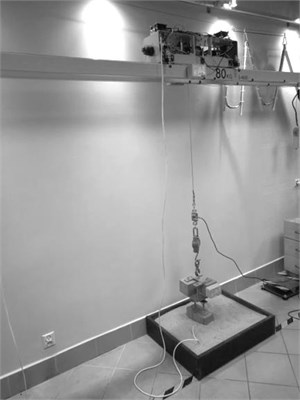
The proposed test stand is shown in Fig. 1. Table 1 shows the general characteristics of the tested overhead traveling crane, prepared by the technical documentation. The proposed scale model reflects the real object, corresponding to the bridge crane. The scaled object cannot only move the bridge structure. The more extensive mechatronic model of the crane is described in the publication [10, 11].
3. Numerical model of lifting mechanism
The phenomenological model of the experimental crane is shown in Fig. 2. This model contains in its structure, girder, drum, rope and the substrate on which the load rests together with the electromagnetic release mechanism of the test load part.
By the concept of generalized coordinates, and phenomenological model shown in Fig. 2, the equations of motion can be written as second type Lagrange equations [7, 12]. This approach allows obtaining the differential equations of motion that are presented in paper [10]. In Matlab-Simulink environment the dynamic model was formulated. Table 2 shows the physical parameters describing the considered vibrating model. Then the numerical experiments for the data presented and the assumed initial conditions with the classical model of the elastic-damping model (Kelvin-Voigt) for the wire rope was performed.
Fig. 2The phenomenological model of the investigated experimental crane
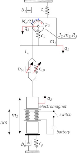
As the extortion signal is used as constant driving torque corresponding to the fast start of the engine, without the control system, in the worst case, but in this case, it is not as important because we consider vibration signal after the start of the motor. Simulations were carried out using algorithm ode4, with the constant step of integration 1E-05 s. Simulations were performed for a load value of 45 kg located in the middle of the girder, and the dropped mass has a value of 23 kg. After a series of numerical experiments, some model parameters were obtained, such as girder and cargo accelerations and also the force acting on wire rope.
Table 2Physical parameters describing the dynamic system
No. | Symbol | Value | Unit | No. | Symbol | Value | Unit |
1 | m1 | 45 | [kg] | 13 | L0 | 2 | [m] |
2 | m2 | 22,6 | [kg] | 14 | Al | 2,826e-5 | [m2] |
3 | m3 | 1 | [kg] | 15 | ρl | 7850 | [kg/m3] |
4 | mliny | 2.22 | [kg] | 16 | Es | 2,1e011 | [Pa] |
5 | J3 | 0,0039 | [kgm2] | 17 | El | 1,155e011 | [Pa] |
6 | c1 | 4e5 | [N/m] | 18 | g | 9,81 | [m/s2] |
7 | cp | 2,0e8 | [N/m] | 19 | Vp | 0,12 | [m/s] |
8 | c3 | 1,8e8 | [N/m] | 20 | nlin | 1 | [–] |
9 | bp | 1,0e6 | [Ns/m] | 21 | ζ | 0,07 | [–] |
10 | b1 | 2e3 | [Ns/m] | 22 | iw | 1 | [–] |
11 | R3 | 0,08 | [m] | 23 | Δm | 23 | [kg] |
12 | dl | 0,003 | [m] |
4. Simulation and test stand tests
A series of experiments were conducted at this research test stand to examine the effect of the sudden release of part of the load on the force in the wire rope and acceleration of the center of the girder. For research purposes, a test mass load was used of 45 kg. The mass to be released during lifting is 23 kg, as shown in Fig. 4.
Fig. 3Test stand and measurement nodes location, 1, two measurement nodes for measuring girder acceleration
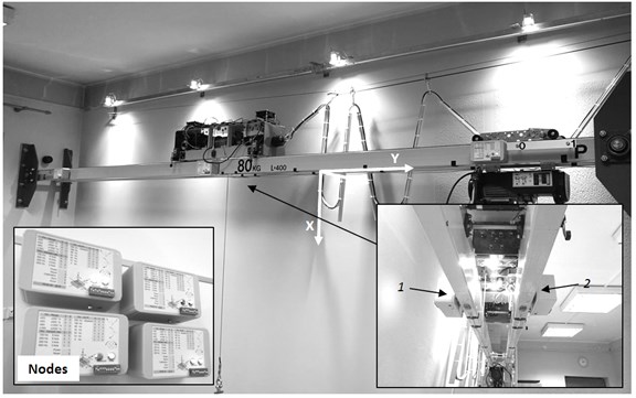
Fig. 4Test stand and measurement nodes location, 1 – electromagnetic gripper with the load to drop, 2 – node for measuring the acceleration of the cargo, 3 – cargo, 4 – S load type cell, 5 – power source for the electromagnetic gripper
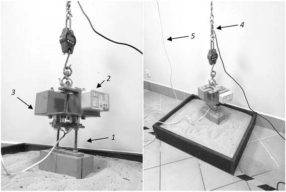
The process of releasing the cargo was realized through a simple mechanism of electromagnetic coupling, remotely releasable after extinguishing the vibration caused by the lifting in the start-up phase. The research program includes to determining acceleration values in the three selected points, including girders and the cargo. Also, the test force acting on the rope lifting mechanism was measured. The sensor layout is shown in the Fig. 3, 4. The study program included lifting the load from the ground with the assumption of a tight rope in the initial phase of the lifting process and the sudden release of part of the load using the electromagnetic head between the base load and the released load.
5. Results
The measurements were made using a set of experimental wireless acceleration sensors based on the MPU6050 board, with 16-bit resolution with a sampling rate of 500 Hz for three measuring axes (Fig. 3).
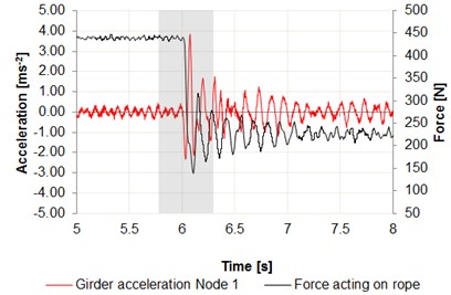
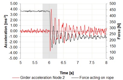
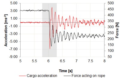
Fig. 6Time intervals of the acceleration changes: a) center of the girder – node 1, b) center of the girder – node 2, c) cargo in relation to the force acting on wire rope
a)
b)
c)
Data were recorded using the Bluetooth interface, on a laptop computer. Measurement nodes are set as shown in Figs. 3, 4. The measurement was performed in the central position of the girder on both the front and rear beam. Force measurement was made using the S Type Load Cell for measuring the force with a resolution transducer 24-bit, downloading data with 125 Hz sampling rate. The results are summarized in Fig. 6. A significant increase in acceleration can be observed on the graphs, especially in case of sudden release of cargo, where the acceleration values reach 4 m/s2 for the center of the girder and 7 m/s2 for the cargo.
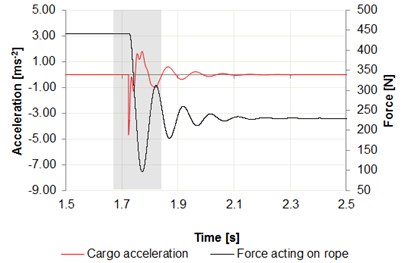
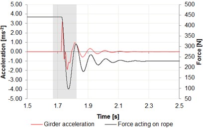
Using the presented phenomenological model some numerical tests were performed including load lifting simulation with the sudden release of cargo. The results of the simulations are shown in Fig. 7, in the form of the time course of acceleration changes of the center of the girder, cargo in relation to the force acting on the wire rope.
Fig. 7a) Time intervals of acceleration changes cargo, b) center of the girder in relation to the force acting on wire rope
a)
b)
As can be seen in Fig. 7, the acceleration values in the phase of release of the cargo reach 5 m/s2 for cargo, where for the girder these values reach 3 m/s2. As shown in Fig. 7, these values are similar to those obtained by experimenting on a real object (Fig. 6). When measuring the acceleration value of the lifted cargo, the difference is 2 m/s2 taking into account the absolute maximum values. This large difference can be caused by swaying load in the process of releasing the cargo.
When measuring the acceleration value on the girder, the difference is 1 m/s2 taking into account the absolute maximum values. Comparing the force in the wire rope, the maximum value obtained by measuring on a test bench is 138 N in case of simulation the force value is 101 N.
6. Conclusions
The experimental research station presented in the article it enables some studies typically associated with the dynamics of hoist mechanisms. As shown, results from the presented preliminary studies and values obtained by numerical experiment they are close to each other, which shows a good fit of the numerical model, despite its simplicity.
After initial research, it is stated that the test stand for testing dynamics of cranes fulfills its role, providing tremendous opportunities for verifying research on the proposed phenomenological models of these mechanisms. The proposed test stand is therefore applicable to evaluate the effectiveness of the elimination of mechanical vibrations transferred to the structure during the lifting process including the sudden release of a part of the load.
References
-
Margielewicz J., Haniszewski T., Gąska D., Pypno C. Model Studies of Cranes Hoisting Mechanisms. Polish Academy of Science, Katowice, 2013, p. 204.
-
Security of Cranes. General Principles for Design. Part 2: Loads. Warsaw, Polish Committee for Standardization, PN-EN 13001-2, 2013.
-
Gąska D., Haniszewski T., Margielewicz J. I-beam girders dimensioning with numerical modeling of local stresses in wheel-supporting flanges. Mechanika, Vol. 23, Issue 3, 2017, p. 347-352.
-
Gąska D., Margielewicz J. Numerical modeling of dynamics of lifting the load. Transport, 2008. Vol. 1, 2008, p. 2-5.
-
Haniszewski T. Modeling the dynamics of cargo lifting process by overhead crane for dynamic overload factor estimation. Journal of Vibroengineering, Vol. 19, Issue 1, 2017, p. 75-86.
-
Haniszewski T. Hybrid analysis of vibration of the overhead travelling crane. Transport Problems, Vol. 9, Issue 2, 2014, p. 89-100.
-
Bogdevičius M., Vika A. Investigation of the dynamics of an overhead crane lifting process in a vertical plane. Transport, Vol. 20, Issue 5, 2005, p. 176-180.
-
Markusik S., Gąska D., Witaszek K. Study of Acceleration and Vibration Levels in Bridge Cranes. Gliwice, 2007, p. 181-186.
-
Piątkiewicz A., Sobolski R. Cranes. WNT, Warszawa, 1978.
-
Haniszewski T. Preliminary modelling studies of an experimental test stand of a crane, for its dynamics phenomena of lifting and driving mechanism investigation. IX International Scientific Conference on Transport Problems, Katowice, 2017.
-
Haniszewski T. Conception of the Arduino platform as a base for the construction of distributed diagnostic systems. Transport, Vol. 93, 2016, p. 31-40.
-
Cannon R. H. Dynamics of Physical Systems. WNT, Warszawa, 1973, p. 930.

