Abstract
Aiming at attenuating the vibration of a precision instrument in spacecraft, multiple particle dampers are designed and their damping performances are evaluated. Firstly, the vibrating table test for the primary system under sin-swept excitation is conducted to acquire the vibration characteristic. Then enclosures attached to the installing bracket are designed and fabricated elaborately. Using discrete element-finite element (DE-FE) coupling algorithm, the effects of some system parameters (such as: mass ratio, particle material, numbers of dampers and cavity depth) are investigated to optimize the damping capacity of particle dampers. Furthermore, a series of experiments are conducted to verify the performance of particle dampers under dynamic load. The results indicate that the transfer functions of acceleration in Y and Z direction decrease at 22.58 % and 77.38 % respectively, while only 3.1 % mass of the primary system is attached.
1. Introduction
Generally, structural damping of a spacecraft is very small. When the system is disturbed (such as posture alignment, docking collision, structure stretching, etc), the intense and sustained vibration may occur, which may adversely affect the normal operation of spacecraft. Moreover, the performance of conventional damping devices made of viscoelastic material and viscous fluids is poor at extreme low and high temperature, with materials degrading problem over time. Particle dampers [1], with the advantages of ruggedness, reliability, and insensitivity to extreme temperatures, are simple and efficient passive devices, especially in harsh environment where conventional approaches may fail to function. In contrast to viscoelastic materials which dissipate the stored elastic energy, particle damping treatment focuses on energy dissipation in a combination of collision, friction and shear damping [2]. Up to now, particle dampers have been widely used for structural damping applications in skyscrapers [3], civil structures [4], automotive [5] and other lightly damped structures [6].
Recently, many theoretical, numerical, and experimental studies have been carried out on the characterization of particle dampers. Araki et al. [7] investigated the characteristics of particle dampers with granular materials in a single-degree-of-freedom (SDOF) system that was subjected to an external sinusoidal force. Saeki [8] evaluated the damping efficiency of an impact damper with granular materials in a horizontally vibrating system under sinusoidal excitation. Papalou and Masri [9] introduced an equivalent single-particle impact damper model to evaluate the performance of multi-particle dampers. Liu et al. [10] used an equivalent viscous damping model to represent the nonlinearity which was extracted from experimental results. Lu [11] presented the concept of effective momentum exchange (EME) to quantitatively characterize some of the physics of particle dampers. Fang and Tang [12] developed an improved analytical model by multiphase flow theory based on the previous work of Wu et al. [13].
Despite all these efforts, due to the high nonlinearity resulting from the impact and friction of particles and the great number of particles in the damper, the research on design of the particle damper has still not been well developed. It can be noted that most studies have investigated the performance on SDOF or Dual-Degree-of-Freedom (DDOF) systems. However, for most structures found in engineering, such as the case of complicated installing brackets in spacecraft, the structures cannot reasonably be approximated as a SOF system, since the damper’s nonlinear interactions tend to excite more than just the fundamental mode of vibration. The performance of Multiple-Degree-of-Freedom (MDOF) system equipped with particle dampers, which involves coupling vibration in multi-directions, is seldom implemented.
In this paper, authors apply the multiple particle dampers to attenuate the vibration of the MDOF system in spacecraft. The discrete element-finite element (DE-FE) coupling algorithm is utilized to investigate the effect of key parameters for the design of particle dampers. The performance of particle dampers attached to the installing bracket under sin-swept excitation is evaluated through the experiment. Moreover, the research may also provide some guidelines for the vibration reduction of complicated structures in harsh environment.
2. Vibration characteristic and requirements analysis
Fig. 1 depicts the profile of a precision instrument in spacecraft, which consists of high-speed component, installing bracket and low-speed component. The high-speed component is connected to the installing bracket mounted to the low-speed component through the adapter plate. The precision device in the high-speed component is very sensitive to vibration and can’t work reliably or even fail under severe vibration. The low-speed component is excited with a wide frequency band. And this vibration will be transferred to the high-speed component through the installing bracket. According to the operating requirements, the damping devices can only be placed in the installing bracket. Therefore, it’s essential to choose one proper passive damping device to reduce the vibration.
Fig. 1Profile of the precision instrument
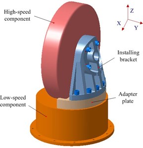
Fig. 2A picture of the experimental apparatus
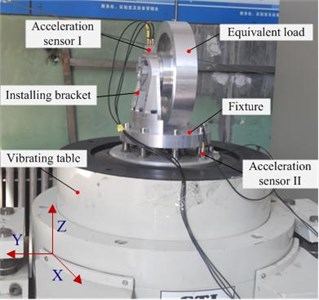
To have a better understanding of vibration characteristic of the primary system, the bench test is conducted as shown in Fig. 2. The low-speed component is not considered in the experiment for its stiffness is much larger than that of other components. The high-speed component is replaced with an equivalent load with the same mass and moment of inertia. The electromagnetic vibrating shaker is used to generate the signal of sin-swept in Z direction. The frequency range is 20-2000 Hz with the amplitude of 8.1 g, and the vibrating duration is 2 min. An acceleration sensor stuck on the top of the bracket is to measure the vibrations in three directions and another acceleration sensor stuck to the vibrating table is to measure the vertical input response.
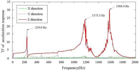
Driven by observation, output energy of the vibrating table fluctuates, especially nearby the resonant regions. Hence, transfer function (‘TF’ in the figures) of acceleration response (response of installing bracket/response of vibrating table) is utilized to reveal the vibration isolating property. Fig. 3 shows transfer function of the primary structure in X, Y and Z direction. Only one peak response in Y direction can be clearly identified at 239.0 Hz, which corresponds to the system’s first natural frequency. The energy in Z direction mainly distributes in three resonant regions, which reveals that modeling the system by a SDOF is insufficient to describe the correct system behaviors. The response in X direction is relatively small, which will not be taken account in the following research.
Fig. 3Transfer function of primary system in X, Y and Z direction
Passive dampers such as metal rubbers [14], dynamic vibration absorber [15] and particle dampers are good candidates for vibration reduction in harsh environment. However, the metal rubber with the advantage of decreasing relative motion of different bodies is difficult to be designed for this system. Although dynamic vibration absorber is effective to reduce the vibration of single frequency, it is hard to be used because the response energy in Z direction is widely distributed. With the special mechanism of attenuating vibration, particle damper is found to be proper to suppress response both in Y and Z direction. Moreover, the particle dampers can be designed flexibly with rarely changing the system.
3. The damping characteristic of particle damper
3.1. Discrete element – finite element coupling algorithm
DE-FE coupling algorithm is utilized to simulate the behavior of the system equipped with particle dampers, where discrete element method (DEM) is to capture the contact of particles and finite element method (FEM) is to calculate the response of the system [16-17]. With this technique, the position and contact force of the individual particle and the primary system can be traced at every single time step.
In the DEM, Newton’s Second Law is used to determine the motion of each particle arising from the contact forces, while the force-displacement law is used to update the contact forces arising from the relative motion at each contact. It is assumed that the time step Δt may be so small that no new contacts are generated in that time step, and the forces acting on one particle cannot pass to any other particles.
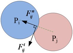
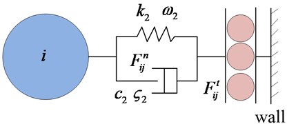
Fig. 4The model of particle contact
a)
b)
Contact force model [18, 19] regulates the normal force and the tangential force, as shown in Fig. 4(a). In Fig. 4(b), a stiff spring and a viscous dashpot are acting in parallel to simulate the normal contact force between a particle with the mass of m and the wall. Parameters k2 and c2 are the stiffness and the damping constant of the impact damper “stops”, respectively (“stops” are used here to name the combined mechanics of the spring and the dashpot between the particle and the wall) [20]. The variable ω2=√k2/m is the natural frequency, which can be used to simulate a cavity wall. The parameter ς2=c2/2mω2 is the damping ratio, which can be used to simulate impacts. Similarly, k3, ω3, c3 and ς3 are the stiffness, natural frequency of the spring, damping coefficient, and damping ratio of the damper, respectively. Hence, the normal contact force is expressed by:
where δn and ˙δn are the relative displacement and relative velocity of particle i relative to particle j in the normal direction, respectively; Δi is the distance from the center of particle i to the wall; Pi and Pj are the position vector of the center of gravity of particle i and j, respectively.
Particle sliding occurs when the actual interparticle tangential force exceeds the maximum tangential resistance force. Considering Coulomb’s friction, the tangential contact force is expressed by:
where μs is the friction coefficient between any two particles or between a particle and the wall of the cavity, and ˙δt is the velocity of particle i relative to particle j or the wall, in the tangential direction.
Fig. 5Simulation flowchart of DE-FE coupling algorithm for particle damper system
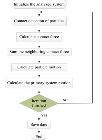
For clarification, the DE-FE coupling algorithm for calculating the response of particle damper system is summarized in the flowchart as Fig. 5.
3.2. Effects of some key system parameters
The design and fabrication of enclosure for the installing bracket are carried out in detail in Section 4.1. It will take much effort to choose the design parameters to achieve best performance totally depending on experiments. There is a need to investigate the damping performance of particle dampers using DE-FE coupling method.
To reduce computational cost as possible, some assumptions and simplifications are introduced in modeling process. All particles are assumed to be perfect spheres with the same diameter of 2 mm. As peak responses only occur at three resonance regions, the wide frequency band of 20-2000 Hz is replaced with three narrow frequency bands, namely 220-240 Hz, 1155-1185 Hz and 1550-1600 Hz. The narrow frequency bands can completely cover the resonance regions while only 5 % frequency band is calculated. The parameters of particles such as density, Young’s modulus, friction coefficient and restitution coefficient are derived from the previous work of authors [16].
As documented in the previous work [19], the damping capacity of particle damper depends on many factors. In our work, we concentrate on the some system parameters, which are closely related to the design of particle dampers for this system. 24 cases with different parameters are calculated and simulation results are summarized. Fig. 6 presents the comparison of responses against the particle density and mass ratio. Increasing the mass ratio can improve the damper’s effectiveness but only up to a certain level. The larger the density of particle is, the better the performance is when other parameters remain constant. Fig. 7 shows the effect of cavity depth and layout of dampers. For this system, the performance is better when two dampers are placed at upside compared to the downside. The dampers with larger depth should be applied if possible. It can be noted that the effects of key parameters are towards the same trend in Y and Z direction.
Fig. 6Effect of particle density and mass ratio
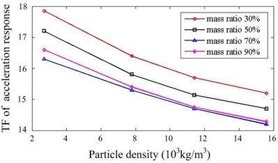
a)Y direction
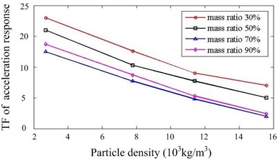
b)Z direction
Fig. 7Effect of cavity depth and layout of dampers
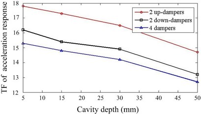
a)Y direction
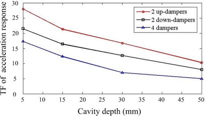
b)Z direction
4. Experimental verification
4.1. Design of particle dampers
Fig. 8 presents the first five computed natural frequencies and the corresponding mode shapes of the primary system. The natural frequencies agree well with the experimental results, as shown in Fig. 3. It is noted that the 2nd and 3rd modes are not totally activated as only excitation in Z direction is applied. The simulations in section 3.2 also depends on this verified FE model. Learning from Friend [21] and Marhadi [22], who considered a higher value of damping capacity could be achieved by placing a particle damper on the structure in region of high displacement, the particle dampers are mounted on the upside of the bracket to acquire the vigorous motion of particles.
Fig. 8First five computed mode shapes
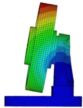
a) 1st mode shape, f1=237.8 Hz
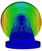
b) 2nd mode shape, f2=451.9 Hz
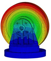
c) 3rd mode shape, f3=734.5 Hz
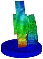
d) 4th mode shape, f4=1162.2 Hz
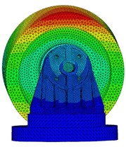
e) 5th mode shape, f5=1557.2 Hz
Fig. 9Profile of particle dampers
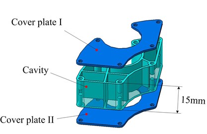
a) A-damper
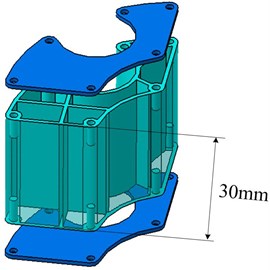
b) B-damper
A particle damper cosists of a enclosure partially filled wth a multitude of solid particles. In order to add more particle, the enclosure shape matches the groove of the installing bracket as well as possible. Fig. 9 illustrates the construction of a enclosure including cover plate I, cavity and cover plate II. To avoid particle aggregation causing slowdown of particles under the gravity, the civity is divided into several parts with thin ribs. The enclosure is made of allumium alloy for its advantage of low density. Wire-electrode cutting approach is used to achieve the complicated shape. The cavity depth can be adjusted flexibly while the cross-section remains unchanged. The enclosures with depth of 15 mm and 30 mm are respectively fabricated, namely A-damper and B-damper, as shown in Fig. 9(a) and 9(b). The tungsten carbide (TC) particle with size of 20 mesh and lead sphere of diameter 2 mm are chosen as particle material due to their higher density. The maximum mass of 231.6 g will be attached when four B-dampers filled with 90 % TC particles are applied, at a percentage of 3.1 % to the primary system mass. The design procedure combines the realistic consideration and the simulation conclusions.
4.2. Experiment program
To verify the simulation results and inspect the damping performance, four different cases are implemented in the experiment as follows:
1) Four B-dampers filled with 0 %, 50 %, 70 % and 90 % TC particles are applied respectively, aiming to investigate the effect of mass ratio, as shown in Fig. 10(a).
2) Four B-dampers are applied filled with 70 % lead particles are applied compared to the 70 % TC particles, aiming to investigate the effect of particle material.
3) Two B-dampers are applied filled with 50 % TC particles compared to the four A-dampers, aiming to investigate the effect of number of dampers, as shown in Fig. 10(b).
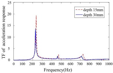
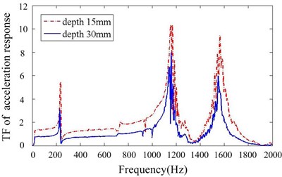
4) Four A-dampers are applied filled with 70 % TC particles compared to the B-dampers, aiming to investigate the effect of cavity depth.
The initial conditions remain same for all these experiments. Each case is tested 3 times and the mean TF of acceleration response is calculated and utilized in the next section.
Fig. 10Layout of particle dampers
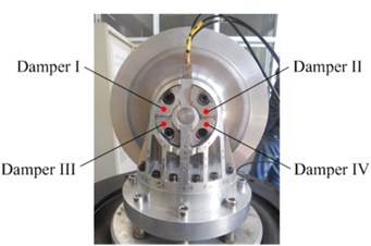
a) Four dampers
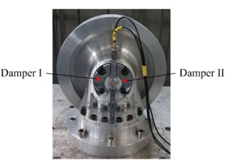
b) Two dampers at upside
4.3. Results and discussions
Figs. 11-14 depict transfer function of acceleration responses for the key parameters such as mass ratio, particle material, layout of dampers and cavity depth. They indicate that: (1) the responses are much reduced when particle dampers are placed to the promary system. The 1st resonance peaks decrease respectively 22.58 % and 78.24 % in Y,Z direction, when four B-dampers filled with 70 % TC are applied. (2) larger density of material is helpful to reduce vibration while others parameters kepp same. (3) the vibration attenuation is better when using four dampers instead of two ones. This is understandable, but the effect versus the number of dampers is not linear. (4) the vibration attenuation of B-damper is better than A-damper for its greater depth. Also the effect versus cavity depth is not linear. (5) it does not occur that the response in one direction decreases while the response in other direction increases. In other word, the vibrations of Y and Z direction may be both controlled effectively by applying particle dampers.
Fig. 12Transfer function of acceleration response for different mass ratios
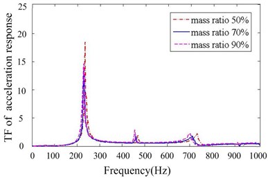
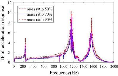
Fig. 13Transfer function of acceleration response of different particle materials
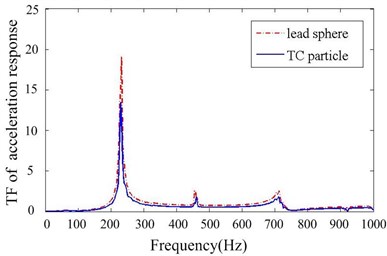
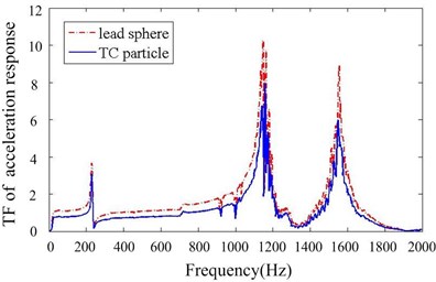
Fig. 14Transfer function of acceleration response for different numbers of particle damper
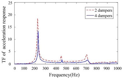
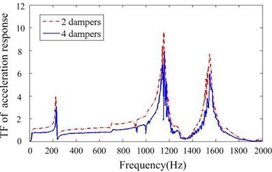
Fig. 15Transfer function of acceleration response for different particle damper depths
5. Summary and conclusions
Although many researchers have presented the results of simulations and experiments of particles dampers, the particle damper attached to MDOF primary system is seldom investigated. In this paper, particle damper is selected to attenuate the vibration for a precision instrument in the spacecraft after analyzing the vibration characteristic of the primary system. The enclosures attached to installing bracket are designed flexibly to match the primary system. In order to maximize the damping performance of particle dampers, DE-FE coupling algorithm is utilized to simulate the effect of some system parameters, which are closely related to the experiment. Finally, a series of vibrating table tests are designed and conducted to evaluate the performance of particle dampers. Some conclusions are reached as follows:
1) By using a properly designed particle damper, a lightly damped primary system can achieve a considerable reduction in its response with a small weight penalty.
2) Choosing a suitable mass ratio and larger density of material are helpful to decrease the vibration. Additionally, more numbers of dampers with larger size should be applied if possible.
3) With the particular mechanism of attenuating vibration, responses of structures equipped with particle dampers generally decrease in multi-directions simultaneously.
4) DE-FE coupling algorithm is effective to simulate the performance of particle dampers attached to MDOF system, which can provide the optimum strategies for maximizing their behavior.
References
-
Masri S. F.,Caughey T. K. On the stability of the impact damper. Journal of Applied Mechanics, Vol. 33, Issue 3, 1966, p. 586-592.
-
Panossian H. V. Structural damping enhancement via non-obstructive particle damping technique. American Society of Mechanical Engineers Journal of Vibration and Acoustics, Vol. 114, 1992, p. 101-105.
-
Duan Y., Chen Q., Lin S. Experiments of vibration reduction effect of particle damping on helicopter rotor blade. Acta Aeronautica et Astronautica Sinica, Vol. 30, Issue 11, 2009, p. 2113-2118.
-
Carpenter L. D., Naeim F., Lew M. Performance of tall buildings in Viña del Mar in the 27 February 2010 offshore Maule, Chile earthquake. The Structural Design of Tall and Special Buildings, Vol. 20, Issue 1, 2011, p. 17-36.
-
Liu X., Hou J., Shan Y. Application of particle damping absorber to vibration and noise control of drum brake. Journal of Vibration Measurement and Diagnosis, Vol. 28, Issue 3, 2008, p. 247-302, (in Chinese).
-
Daniel N. J. Els. Damping of rotating beams with particle dampers: experimental analysis. AIAA Journal, Vol. 49, Issue 10, 2011, p. 2228-2238.
-
Araki Y., Yokomichi I., Inoue J. Impact damper with granular materials. II: Both sides impact in a vertical oscillating system. Bulletin of the JSME, Vol. 28, Issue 241, 1985, p. 1466-1472.
-
Saeki M. Impact damping with granular materials in a horizontally vibrating system. Journal of Sound and Vibration, Vol. 251, Issue 1, 2002, p. 153-161.
-
Papalou A., Masri S. F. An experimental investigation of particle dampers under harmonic excitation. Journal of Vibration and Control, Vol. 4, Issue 4, 1998, p. 361-379.
-
Liu W., Tomlinson G. R. Rongong J. A. The dynamic characterization of disk geometry particle dampers. Journal of Sound and Vibration, Vol. 280, Issue 3-5, 2005, p. 849-861.
-
Lu Z., Masri S. F., Lu X. Studies of the performance of particle dampers attached to a two-degrees-of-freedom system under random excitation. Journal of Vibration and Control, Vol. 17, Issue 10, 2011, p. 1454-1471.
-
Fang X., Tang J. Granular damping in forced vibration: qualitative and quantitative analyses. Journal of Vibration and Acoustics Transactions of the ASME, Vol. 128, Issue 4, 2006, p. 489-500.
-
Wu C. J., Liao W. H., Wang M. Y. Modeling of granular particle damping using multiphase flow theory of gas-particle. Journal of Vibration and Acoustics Transactions of the ASME, Vol. 126, Issue 2, 2004, p. 196-201.
-
Chen Y. Q., Guo B. T., Zhu Z. G. The investigation of the stiffness characteristics and the stress-strain relation of metal rubber. Journal of Aerospace Power, Vol. 17, Issue 4, 2002, p. 416-420.
-
Zilletti M., Elliott S. J., Rustighi E. Optimisation of dynamic vibration absorbers to minimise kinetic energy and maximise internal power dissipation. Journal of Sound and Vibration, Vol. 331, Issue 18, 2012, p. 4093-4100.
-
Xia Z., Liu X., Shan Y. Coupling simulation algorithm of discrete element method and finite element method for particle damper. Journal of Low Frequency Noise, Vibration and Active Control, Vol. 28, Issue 3, 2009, p. 197-204.
-
Xia Z., Liu X., Shan Y. Coupling simulation algorithm of dynamic feature of a plate with particle dampers under centrifugal loads. Journal of Vibration and Acoustics, Vol. 133, Issue 4, 2011, p. 041002.
-
Lu Z., Lu X., Jiang H. Discrete element method simulation and experimental validation of particle damper system. Engineering Computations, Vol. 31, Issue 4, 2014, p. 810-823.
-
Lu Z., Masri S. F., Lu X. Parametric studies of the performance of particle dampers under harmonic excitation. Structural Control and Health Monitoring, Vol. 18, Issue 1, 2011, p. 79-98.
-
Masri S. F., Ibrahim A. M. Response of the impact damper to stationary random excitation. The Journal of the Acoustical Society of America, Vol. 53, Issue 1, p. 200-211.
-
Friend R. D., Kinra V. K. Particle impact damping. Journal of Sound and Vibration, Vol. 233, Issue 1, 2000, p. 93-118.
-
Marhadi K. S., Kinra V. K. Particle impact damping: effect of mass ratio, material and shape. Journal of Sound and Vibration, Vol. 283, Issue 1, 2005, p. 433-448.
About this article
This work was finically supported by the National Science Foundation of China (Grant No. 51275022).
