Abstract
This research aims at identifying the position and depth of the open transverse crack of the beam using the model based method. The stiffness matrix of the cracked beam element and the basic principle of the model based method are introduced. It is discussed to estimate the generalized displacement of all nodes of the beam by the measured displacements of a few degrees of freedom. The relative change rate of the equivalent external load between the intact and cracked elements is compared with that of mode shape, nature frequency and displacement amplitude between the intact and cracked beam. The position and depth of the crack are identified by the model based method in two cases. In first case, the measured displacement is assumed not to include noise. The identification results based on the actual displacement and rotation of all nodes are compared with the results using the estimated generalized displacement. In second case, the measured displacement includes noise and the generalized displacement of all nodes is estimated by the displacement of two measurement points. The simulation results shown there is no error to identify the position, the relative depth identification error of the crack with 1 μm depth is 2.34 % without noise, and the relative depth identification error of the crack with 200 μm depth could be down to about 5 % with the energy signal to noise ratio being about 7.00 before denoising.
1. Introduction
The beam is the common structural element of the building or civil and the mechanical engineering. It could withstand the bending moment and the shear force primarily. If the beam failure occurs during service, it should leads to the huge economic lost or the casualties. The failure due to crack might be the common one. Therefore, it is very important to identify the position and depth of cracks existing in the beam as early as possible for avoiding the failure appearance.
There have been a lot of reported methods for the identification of the position and depth of cracks of the beam. One of those methods was based on the difference of natural frequencies between the cracked and intact beam. The type method has been widely used to identify the transverse cracks of the beam or shaft [1-6] and it was also employed to detect longitudinal cracks of the beam [7]. The method based on experimental natural frequencies, characteristic equation and local flexibility expression of the cracked element was reported by Chen et al. [8, 9]. A contour line of the normalized frequency or FRF (frequency response function) amplitude change resulting from a combination of different crack depths and locations was employed to detect the cracks of a beam by Owolabi et al. [10]. The second type method by analyzing mode shapes has been reported by some literatures, such as [11, 12]. The third type method was used for identifying cracks by processing the forced vibration response. For example, the depth and position of cracks were identified by minimizing the difference between the measured and calculated forced vibration response [13]. In this method, the initial crack parameters were obtained from the difference in mode shape curvature between the intact and the cracked beam. The method based on the forced vibration response of the cracked beam was discussed by Law et al. to detect the single or multiple cracks [14]. Another type method was the hybrid one where any two or multiple variables of natural frequency, mode shape, forced vibration response, FRF, mechanical impedance, and so on were employed, such as [15, 16].
Model based method was firstly reported to identify the faults of rotating machinery by Diana [17], Penny [18], Bachschmid [19] and Mayes [20] in the mid-nineties of the last century. This method allows using a priori information of the system in identification process and can give more precise and reliable information about the growing faults [21-22]. It has been proved that the model based method can exactly identify the type, position and other information of many common faults of the rotor system by a lot of articles which have been summarized by the author [23]. Nowadays, the model based method has only been employed to identify the faults of the rotor system. But, it is also suitable for a system whose dynamical behavior can be described by the linear dynamics theory. To expand the application of the model based method, the simulation analysis of identifying the position and depth of the open transverse crack of the beam using the model based method is presented. The paper is organized as follows: the stiffness matrix of a cracked beam element and the model based method are briefly recalled, the approach to estimating the generalized displacement of all nodes of the beam is discussed, the outstanding crack resolution of the model based method is demonstrated, and the position and depth of the crack are identified by the model based method with and without noise respectively.
2. Model based identification method of cracks in beam
2.1. Stiffness matrix of a cracked beam element
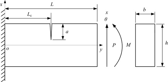
A cracked cantilever beam subjected to shearing force and bending moment under the conventional FEM co-ordinate system is shown in Fig. 1. Here, the total strain energy of the cracked beam element is [24]:
where W(0) is the strain energy of an element without a crack and W(1) is the additional strain energy due to the crack. W(1) can be calculated by:
where E'=E for plane stress, E'=E/(1-ν2) for plane strain, E is the elastic modulus, ν is the Poisson ratio, K1M and K1P are stress intensity factors for opening type due to bending moment M and shearing force P respectively, and K2P is stress intensity factors for sliding type due to shearing force P. K1M, K1P and K2P are respectively expressed by [24, 25]:
F1(s) and F2(s) are formulated as following:
The additional flexibility due to crack is:
Fig. 1Cracked cantilever beam subjected to shearing force and bending moment under the conventional FEM co-ordinate system
When the shearing strain energy is neglected, the strain energy and the flexibility of an element without a crack are respectively:
The entry in the mth (m= 1, 2) row and nth (n= 1, 2) column of the total flexibility matrix C of a beam element with a crack is:
Fig. 2Cracked beam element subjected to shearing force and bending moment under the conventional FEM co-ordinate system
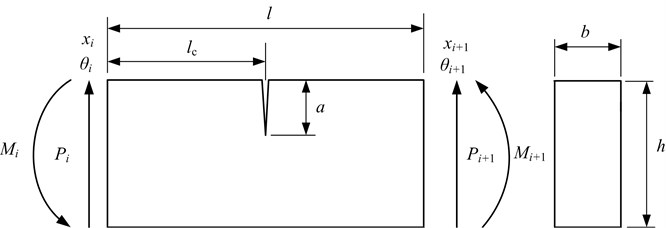
The cracked beam element subjected to shearing force and bending moment under the conventional FEM co-ordinate system is shown in Fig. 2. The equilibrium condition is [24]:
where TT=[-1-l100-101]. According to the flexibility definition, there is:
Substituting Eq. (13) into Eq. (12), it is:
Therefore, the stiffness matrix of the cracked element is:
2.2. Model based identification method of cracks of beam
The linear differential equation of motion of the intact beam with N degrees of freedom excited by the original external load F0(t) are described by [26]:
where M, C, K, X0, ˙X0 and ¨X0 are the mass matrix, damping matrix, stiffness matrix, generalized displacement, generalized velocity and generalized acceleration of the beam oscillation respectively.
When one or multiple open cracks occur, the dynamical behavior of the considered beam will change and it depends on the position and depth of cracks. The crack-induced change in the dynamical behavior could be represented by the additional external load ΔFt(B,t) acting on the intact beam. ΔFt(B,t) is named as the equivalent external load. The equivalent external load depends on the crack parameters vector B which is composed of the position and depth of the crack. Denote Xt as generalized displacement of the beam oscillation after the crack occurs. Then, the kinetic equation of the cracked beam is described as:
The difference between displacement, velocity and acceleration of the cracked and intact beam are named as residual generalized displacement, velocity and acceleration, respectively. These are given by [27]:
Substitute Eq. (18), (19) and (20) into Eq. (17) and obtains:
Subtract Eq. (16) and yields:
According to Eq. (22), the equivalent external load ΔFt(B,t) could be calculated when the displacement and rotation of all nodes for both the intact and cracked beam are obtained by the sensors and the data acquisition system. It is named as the measured equivalent external load.
The increment of stiffness matrix due to cracks is denoted as ΔK. After the crack occurs, the kinetic equation of the crack beam is described as:
Comparing Eq. (17) with Eq. (23), the theoretical equivalent external load ΔFct(B,t) satisfies:
The least-squares method is employed to identify the position and depth of cracks by the equation:
where a and p are the depth and position (serial number of the cracked element) of cracks, h is the height of the beam.
There is another way of the model based method to identify the depth and position of cracks in a beam. Here, the measured equivalent external load ΔFt(B,t) is replaced by the theoretical equivalent external load ΔFct(B,t) in Eq. (22). That is:
where Δ¨Xct, Δ˙Xct and ΔXct are the theoretical residual generalized acceleration, velocity and displacement respectively. Then, the depth and position of cracks can be identified by Eq. (25) where ΔFt(B,t) and ΔFct(B,t) are replaced by ΔXt and ΔXct, Δ˙Xt and Δ˙Xct or Δ¨Xt and Δ¨Xct respectively [22]. If the only displacement of M nodes (M≤N) is measured, the ΔXct is replaced by the displacement of those nodes corresponding to the measured M nodes.
2.3. Estimation of displacements and rotations of all nodes
In model based method, it is very difficult to measure the rotation and displacement of all nodes for obtaining the ΔFt(B,t) by Eq. (22) and ΔFct(B,t)by Eq. (24). Therefore, the generalized displacement of all nodes must be estimated by the measured generalized displacement of a few degrees of freedom. Generally, the measured displacements do not include the rotations of any node. To solve this problem, Sekhar [25] presented an estimation expression of the displacement and rotation of all nodes which was:
where XM,C, Φ are the measured displacement with M measurement positions (MPs), the measurement matrix and the reduced modal matrix of the considered beam which was composed of K mode shapes respectively. K is less or equal to M and XM=CX.
Two problems should be solved for estimating displacement and rotation of all nodes using Eq. (27). One is how many MPs to be required in order to achieve the allowable estimation accuracy. In general, the more the number of MPs is, the higher the estimation accuracy is. The other is how to distribute the sensors in order to obtain the minimum displacement and rotation estimation error of all nodes. For the first problem, the number of MPs is usually determined by the experiment condition. If there are a large experiment space and length of the researched equipment, the enough sensors and input channels of the data acquisition system, the number of MPs should be as many as possible. The second problem could be solved by:
s.t.(MP1,MP2,…,MPs)∈CsN,
s≤N2-1,
where N, P and s are the total degrees of freedom, the amount of the discrete time and the MP number. CsN is the set of which elements are all combinations of the value s of the input choice vector [1, 2, 3,…, N]. The optimal sensor distribution could be obtained by Eq. (28) using the simulation test before the actual experiment.
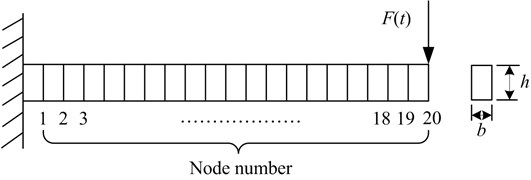
A numerical example should be analyzed to discuss the generalized displacement estimation error of all nodes using Eq. (27). Here, the cantilever beam is considered and its finite element model is shown in Fig. 3. It is divided into 20 elements. The external load F(t) is applied to the 20th node. For the model based method, it is the most favorable for improving the fault identification accuracy to collect the displacement signal but not acceleration or velocity signal. The reason is that the velocity or acceleration can be precisely estimated by the displacement, but the displacement cannot be precisely estimated by the velocity or acceleration because of the unknown initial displacement in the integral operation. The non-contact eddy current sensor is usually employed to detect the displacement. It must be fixed to the additional equipment before the displacement signal acquisition. Therefore, it is difficult to install plenty of eddy current displacement sensors. In the numerical example, the maximum number of the mounted displacement sensors is assumed to be 4.
Fig. 3Finite element model of cantilever beam
Using Eq. (28), the optimal measurement point (OMP) combinations are (19), (5, 20), (3, 6, 7) and (1, 3, 6, 7) for the number of the mounted displacement sensors being 1, 2, 3 and 4 respectively. Under the condition of OMP combination, the estimation errors of all nodes of Fig. 3 for four cases are shown in Fig. 4. From the upper sub-graph of Fig. 4, the maximum displacement estimation error of all nodes during the considered time span (1 second) is almost less than ±5 % for four cases. The displacement estimation accuracy is higher and higher with the increase of the number of the mounted displacement sensors. From the under sub-graph of Fig. 4, the maximum rotation estimation error of all nodes during the considered time span (1 second) is almost less than ±12 % for four cases. The rotation estimation accuracy is only partly improved by increasing the number of the mounted displacement sensors.
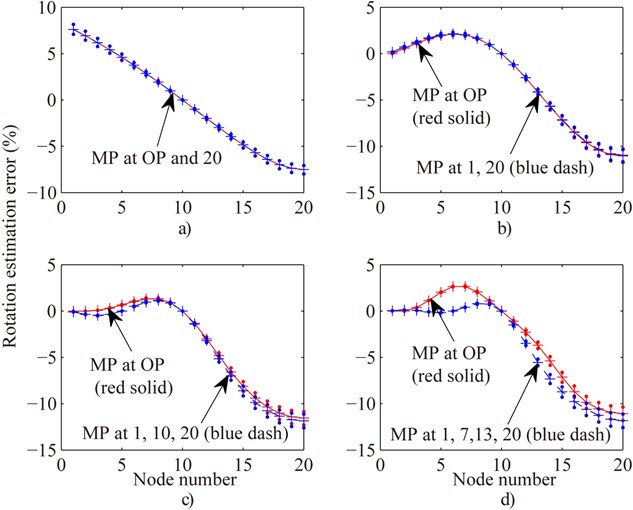
It might take a period of time to seek the OMP using Eq. (28) when the number of the mounted displacement sensors is given. Therefore, it should be helpful to obtain a rule of distributing those displacement sensors. The displacement and rotation estimation errors of all nodes under the condition of evenly distributing MP (MP at free end for only one displacement sensor) are compared with the OMP combination in Figs. 5 and 6 respectively. The maximum difference between the displacement estimation errors of evenly distributing MP and OMP combination is less than ±2 % except for only one displacement sensor case according to Fig. 5. In the only one displacement sensor case, OMP is 19th node which is close to the free end. The rotation estimation errors of evenly distributing MP are very close to the OMP combination from Fig. 6. Therefore, the plan of evenly distributing displacement sensors (MP at free end for only one displacement sensor) might be an acceptable rule.
Fig. 4Displacement and rotation estimation error of all nodes of Fig. 3 under the condition of optimal measurement point (OMP) for one, two, three and four MPs respectively. a) and b) are displacement and rotation estimation error of all nodes respectively. Solid line is the mean error of each node and point (•) above and below mean error are the maximal and the minimum error
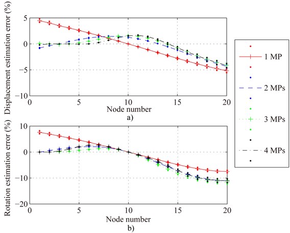
Fig. 5Compare displacement estimation error of all nodes of Fig. 2 in the case of OMP with evenly distributing MP for one (MP at free end) a), two b), three c) and four MPs d) respectively
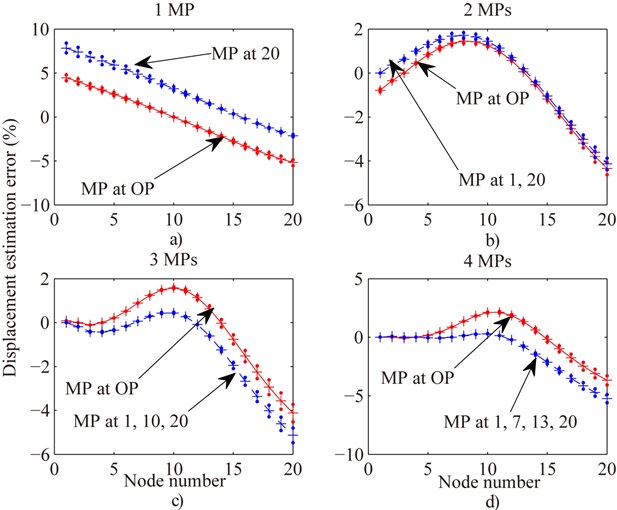
Fig. 6Compare rotation estimation error of all nodes of Fig. 3 in the case of OMP with evenly distributing MP for one (MP at free end) a), two b), three c) and four MPs d) respectively
2.4. Model based identification of cracks of beam without measurement noise
The depth and position of the crack of the cantilever beam should be identified using the model based method in the numerical example. The cross section of the cantilever beam is quadrate. Its height h and width b are equal to 0.04 m and 0.02 m respectively. The total number and length of the element are 20 and 0.03 m. F0(t)=50sin(60t) is applied to the 20th element which is the free end. The elastic modulus E= 2.0×10⁹ (Pa) and the Poisson ratio v= 0.3. The density ρ= 2551 (kg/m3) and the damping coefficient c= 0.035.
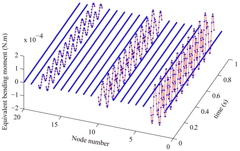
The theoretical and measured equivalent shear force and bending moment are shown in Fig. 7 and Fig. 8 respectively. There are three cracks. They occur at the 3rd(depth 10 μm), 10th (depth 10 μm) and 18th (depth 15 μm) element respectively. According to Figs. 7 and Fig. 8, it could be seen that the equivalent external load of the two end nodes of the crack element is nonzero and that of other nodes are almost equal to zero. The measured equivalent external load (blue dashdot line) is identical with the theoretical one (red solid line) of which the crack parameter vector B is equal to the actual one. Here, the actual displacements and rotations of all nodes are used to calculate the measured equivalent external load.
To demonstrate the outstanding crack resolution of the model based method, the relative change rates of the nature frequency, displacement amplitude, mode shape and equivalent external load of the cantilever beam with one or multiple cracks are listed in Table 1. The maximum relative change rate of the nature frequency is calculated by:
where PFrm and CFrm are the mth order nature frequency of the intact beam and that of the cracked beam respectively. The maximum relative change rate of the mode shape is calculated by Eq. (29) where PFrm and CFrm are respectively replaced by the mth order mode shape of the intact beam and that of the beam with cracks. The maximum relative change rate of the displacement amplitude is:
where PDAm and CDAm are the displacement amplitude of the mth node of the intact and cracked beam respectively. Here, the mean of the relative change rate of amplitude of equivalent external load is compared with the maximum of the relative change rate of nature frequency, displacement amplitude and mode shape. It is:
where EELCAm is the amplitude of the equivalent external load of the node of the element with the mth crack. EELA is the maximum of the equivalent external load of all nodes of all elements without crack. From Table 1, the equivalent external load difference between the nodes of the element with and without crack is far more than the change of the nature frequency, displacement amplitude and mode shape. It means that the crack, especially micro crack might be more precisely identified by the equivalent external load than the nature frequency, displacement amplitude or mode shape.
Fig. 7Compare the measured equivalent shear force (blue point) with the theoretical one (red solid line) where the actual displacement and rotation of all nodes are used to calculate the measured equivalent external load
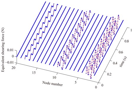
Fig. 8Compare the measured equivalent bending moment (blue point) with the theoretical one (red solid line) where the actual displacement and rotation of all nodes are used to calculate the measured equivalent external load
The identification results of the depth and position of single crack of the cantilever beam are shown in Table 2. The generalized displacements of all nodes of the cracked and intact beam are estimated by Eq. (27) with the measured displacement of the 1st and 20th nodes (evenly distributing two MPs). From Table 1, the position of the crack was identified accurately in all cases and the depth identification error of the 1 μm crack is down to 2.34 %.
Table 1Relative change rate of nature frequency, displacement amplitude, mode shape and equivalent external load of cantilever beam with one or multiple cracks
Case | Position | Depth (μm) | Maximal relative change rate of nature frequency (%) | Maximal relative change rate of displacement amplitude (%) | Maximal relative change rate of mode shape (%) | Mean relative change rate of amplitude of equivalent external load (%) | |
Shear force | Bending moment | ||||||
Single crack | 2 | 100.00 | 2.36×10⁻⁴ | –5.98×10⁻⁵ | 4.19 | 9.31×10⁶ | 3.36×10⁷ |
5 | 10.00 | 4.21×10⁻⁵ | –4.80×10⁻⁷ | 0.16 | 2.32×10⁵ | 4.22×10⁵ | |
10 | 1.00 | 2.02×10⁻⁶ | –8.79×10⁻⁹ | 0.98×10⁻² | 1.69×10⁴ | 3.29×10³ | |
13 | 1000.00 | 1.59×10⁻² | –1.08×10⁻³ | 1.48×10³ | 4.95×10⁶ | 4.86×10⁸ | |
Two cracks | 3 | 100.00 | 2.86×10⁻⁴ | –5.50×10⁻⁵ | 3.96 | 8.38×10⁶ | 1.35×10⁷ |
18 | 10.00 | 2.31×10⁴ | 2.31×10⁴ | ||||
Three cracks | 5 | 10.00 | 1.23×10⁻² | –5.96×10⁻⁴ | 250.92 | 1.80×10³ | 1.62×10⁴ |
10 | 100.00 | 1.04×10⁵ | 8.91×10⁵ | ||||
15 | 1000.00 | 3.97×10⁶ | 3.41×10⁷ | ||||
Table 2Identification results of the depth and position of the crack of the cantilever beam where the actual displacement and rotation of all nodes are used to calculate the measured equivalent external load
Position | Depth (μm) | Identified position | Identified depth (μm) | ||||||
Results | Error (%) | Results (μm) | Error (%) | ||||||
Actual displacement and rotation | Estimated displacement and rotation | Actual displacement and rotation | Estimated displacement and rotation | Actual displacement and rotation | Estimated displacement and rotation | Actual displacement and rotation | Estimated displacement and rotation | ||
2 | 100.00 | 2 | 2 | 0.00 | 0.00 | 100.00 | 99.99 | 1.29×10⁻³ | 1.52×10⁻³ |
5 | 10.00 | 5 | 5 | 0.00 | 0.00 | 9.99 | 9.99 | 1.68×10⁻² | 1.68×10⁻² |
10 | 1.00 | 10 | 10 | 0.00 | 0.00 | 0.98 | 0.98 | 2.34 | 2.34 |
13 | 1000.00 | 13 | 13 | 0.00 | 0.00 | 1000.00 | 999.88 | 0.00 | 1.22×10⁻² |
The measured equivalent external loads of multiple cracks can be calculated by Eq. (25). Due to the linear dynamics system, the residual generalized displacements meet the following equation:
where:
where ΔF'tm(B,t) are the measured equivalent external loads where the only one crack occurs. The crack is in the identical element and it has the identical depth with the mth crack of multiple cracks. Therefore, the measured equivalent external loads of multiple cracks:
The equivalent external load of the two end nodes of the cracked element is nonzero and that of other nodes are almost equal to zero. Then:
where ΔFtm(B,t) is the measured equivalent external load of two nodes which are the end nodes of the nth element with the mth crack of multiple cracks. ΔˆF'tm(B,t) is the measured equivalent external load of two nodes of the cracked element in ΔF'tm(B,t).
The multiple cracks could be identified by:
where ΔFctm(a,t) is the theoretical equivalent external load of two nodes of the cracked element where the only one crack occurs in the nth element of the same dynamical model. Therefore, the identification accuracy of the multiple cracks is almost identical with single crack.
2.5. Model based identification of cracks of beam with measurement noise
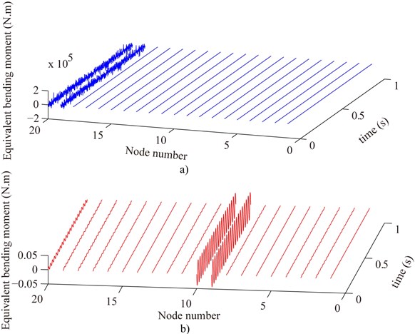
The measured equivalent shearing force and bending moment are shown in upper sub-graphs of Fig. 9 and Fig. 10 before denoising. There is only one crack (depth 300 μm) which occurs at the 10rd element. The generalized displacement of all nodes of the cracked and intact beam are estimated by Eq. (27) where the displacement of the 1st and 20th nodes (evenly distributing two MPs) are measured by the displacement sensors and the data acquisition system. Before denoising, the energy signal to noise ratios of the 1st and 20th nodes of the cracked and intact beam are respectively 7.22, 6.95, 7.47 and 7.03 dB. From the upper sub-graphs of Fig. 9 and Fig. 10, it could be seen that the measured equivalent shearing force and bending moment of the cracked element are completely covered up because of the noise.
Fig. 9Compare the measured equivalent shear force before denoising a) with that after denoising b) where the estimated displacement and rotation of all nodes are used to calculate the measured equivalent external load
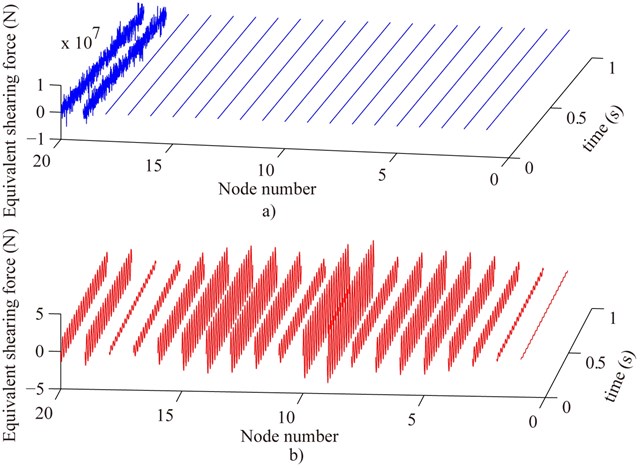
Fig. 10Compare the measured equivalent bending moment before denoising a) with that after denoising b) where the estimated displacement and rotation of all nodes are used to calculate the measured equivalent external load
It is necessary to reduce the noise of the measured displacement for identifying cracks by the model based method. According to Eq. (16), it might be difficult to reduce the noise of the measured displacement because the original external load F0(t) and its characteristic frequency are unknown. Therefore, a method is proposed in this work. F(t) is the known additional external load and is applied to the considered system. The following equations can be obtained:
Then, the generalized displacement X0 and Xt of the model based method are replaced by X02 and Xt2. X02=X01-X0 and Xt2=Xt1-X0 where X0 meets Eq. (16). If the known additional external load is applied to only one node and it fellows the harmonic function with the frequency ω, the frequency of X02 and Xt2 is identical with ω which is known and can be adjusted according to the experiment requirement. When the measured displacement includes the noise, the band-pass filter with the center frequency ω is employed to reduce the noise of the measured point displacement of X02 and Xt2 before using the model based method.
After denoising by the proposed method, the energy signal to noise ratios of the 1st and 20th nodes of the cracked and intact beam are 76.72, 65.97, 105.44 and 84.23 respectively. The measured equivalent shearing force and bending moment are shown in under sub-graphs of Fig. 9 and Fig. 10. It could be seen that the measured equivalent shearing force and bending moment of the cracked element, especially bending moment, are different from that of the intact element again. The identification results of the depth and position of single crack of the cantilever beam are shown in Table 3 in all kinds of energy signal to noise ratios. According to Table 3, the position of the crack was identified accurately in all cases. The depth identification accuracy is enormously lower than those without noise and is relative to the position of the crack with noise. However, if the energy signal to noise ratio of the measured displacement is about 40.00 before denoising, the relative errors of the depth identification for the 100 μm crack are down to 2.05 % and 5.47 % when the crack occurs in the 2nd and 10th element respectively. For 200 μm depth crack of the 2nd and 10th element, the relative errors of the depth identification are down to 1.49 % and 5.27 % when the energy signal to noise ratio of the measured displacement is about 7.00 before denoising.
Table 3Identification results of the depth and position of the crack with the different energy signal to noise ratios
Position | Depth (μm) | Energy signal to noise ratio | Identified position | Identified depth (μm) | |||||||||
Before denoising | After denoising | Results | Error (%) | Results (μm) | Error (%) | ||||||||
Crack | Perfect | Crack | Perfect | ||||||||||
1 | 20 | 1 | 20 | 1 | 20 | 1 | 20 | ||||||
2 | 10.00 | 7.07 | 6.42 | 6.77 | 7.62 | 82.69 | 84.46 | 74.82 | 73.97 | 2 | 0.00 | 20.51 | 105.08 |
39.63 | 40.31 | 38.70 | 39.19 | 118.40 | 84.52 | 115.88 | 82.96 | 2 | 0.00 | 7.81 | 21.88 | ||
100.00 | 3.50 | 2.92 | 3.56 | 3.08 | 83.14 | 84.14 | 62.94 | 84.81 | 2 | 0.00 | 85.94 | 14.06 | |
39.36 | 38.71 | 39.36 | 38.47 | 98.37 | 84.03 | 129.81 | 84.80 | 2 | 0.00 | 102.05 | 2.05 | ||
200.00 | 1.05 | 0.39 | 0.08 | 0.73 | 54.39 | 78.34 | 64.86 | 70.35 | 2 | 0.00 | 197.02 | 1.49 | |
10 | 10.00 | 38.48 | 39.56 | 39.46 | 39.42 | 99.46 | 83.84 | 115.66 | 83.64 | 10 | 0.00 | 29.78 | 197.85 |
100.00 | 6.99 | 6.98 | 6.84 | 7.05 | 65.56 | 71.70 | 81.87 | 55.25 | 10 | 0.00 | 151.86 | 51.86 | |
39.10 | 39.84 | 40.16 | 39.82 | 127.08 | 84.66 | 119.27 | 84.71 | 10 | 0.00 | 105.47 | 5.47 | ||
200.00 | 7.12 | 7.41 | 7.45 | 7.04 | 116.27 | 66.77 | 80.83 | 63.25 | 10 | 0.00 | 189.45 | 5.27 | |
300.00 | 6.02 | 6.88 | 6.83 | 7.14 | 88.64 | 63.81 | 130.19 | 76.46 | 10 | 0.00 | 304.69 | 1.56 | |
18 | 100.00 | 6.68 | 6.15 | 7.12 | 6.73 | 115.80 | 79.25 | 94.94 | 61.67 | 18 | 0.00 | 7.81 | 92.19 |
52.58 | 53.10 | 52.56 | 52.97 | 109.77 | 84.82 | 110.50 | 84.54 | 18 | 0.00 | 125.00 | 25.00 | ||
200.00 | 5.92 | 7.23 | 6.88 | 7.09 | 64.01 | 60.33 | 112.68 | 64.89 | 18 | 0.00 | 15.62 | 92.19 | |
53.44 | 52.64 | 53.30 | 53.13 | 108.33 | 84.89 | 111.86 | 84.51 | 18 | 0.00 | 250.00 | 25.00 | ||
500.00 | 7.87 | 6.66 | 6.90 | 6.60 | 77.81 | 75.06 | 129.99 | 77.11 | 18 | 0.00 | 62.5 | 87.50 | |
52.91 | 52.67 | 53.23 | 53.23 | 141.30 | 84.86 | 115.40 | 84.78 | 18 | 0.00 | 437.50 | 12.50 | ||
1000.00 | 6.36 | 7.45 | 7.09 | 6.44 | 75.31 | 71.24 | 104.12 | 44.63 | 18 | 0.00 | 765.62 | 23.44 | |
40.24 | 40.10 | 38.84 | 38.97 | 116.41 | 84.83 | 98.30 | 84.87 | 18 | 0.00 | 1093.75 | 9.38 | ||
2000.00 | 7.36 | 7.44 | 7.04 | 6.55 | 78.47 | 80.36 | 77.34 | 77.52 | 18 | 0.00 | 1687.50 | 15.62 | |
38.22 | 39.06 | 38.92 | 39.15 | 99.70 | 84.52 | 119.98 | 84.41 | 18 | 0.00 | 1949.22 | 2.54 | ||
3. Conclusions
This work discussed the model based identification method of the depth and position of the open transverse crack of the beam. The crack resolution of the model based method is higher than those methods based on natural frequency, mode shape or forced vibration response. That is, the crack, especially micro crack of the beam might be more precisely identified by model based method. It is acceptable to evenly distribute a few displacement sensors along the beam to estimate the generated displacement. The multiple crack of the beam can be identified by the single crack identification procedure in the model based method. The simulation results show that there is no error to identify the position, the relative depth identification error of the crack with 1 μm depth is 2.34 % without noise and the relative depth identification error of the crack with 200 μm depth is down to about 5 % with the energy signal to noise ratio being about 7.00 before denoising.
References
-
Ding Z., Cao M., Jia H., Pan L., Xu H. Structural dynamics-guided hierarchical neural-networks scheme for locating and quantifying damage in beam-type structures. Journal of Vibroengineering, Vol. 16, Issue 7, 2014, p. 3595-3608.
-
Rajab M., Sabeeh A. Vibrational characteristics of cracked shafts. Journal of Sound and Vibration, Vol. 147, Issue 3, 1991, p. 465-473.
-
Sekhar A., Prabhu B. Crack detection and vibration characteristics of cracked shafts. Journal of Sound and Vibration, Vol. 157, Issue 2, 1992, p. 375-381.
-
Khiem N., Toan L. A novel method for crack detection in beam-like structures by measurements of natural frequencies. Journal of Sound and Vibration, Vol. 333, Issue 18, 2014, p. 4084-4103.
-
Mazanoglu K., Sabuncu M. A frequency based algorithm for identification of single and double cracked beams via a statistical approach used in experiment. Mechanical Systems and Signal Processing, Vol. 30, 2012, p. 168-185.
-
Chasalevris A, Papadopoulos C. Identification of multiple cracks in beams under bending. Mechanical Systems and Signal Processing, Vol. 20, Issue 7, 2006, p. 1631-1673.
-
Thalapil J., Maiti S. Detection of longitudinal cracks in long and short beams using changes in natural frequencies. International Journal of Mechanical Sciences, Vol. 83, 2014, p. 38-47.
-
Chen X., He Z., Xiang J. Experiments on crack identification in cantilever beams. Experimental Mechanics, Vol. 45, Issue 3, 2005, p. 295-300.
-
Li B., Chen X., He Z. I-beam crack identification based on study of local flexibility due to crack. Chinese Journal of Mechanical Engineering, Vol. 24, Issue 6, 2011, p. 116-122.
-
Owolabi G., Swamidas A., Seshadri R. Crack detection in beams using changes in frequencies and amplitudes of frequency response functions. Journal of Sound and Vibration, Vol. 265, Issue 1, 2003, p. 1-22.
-
Douka E., Loutridis S., Trochidis A. Crack identification in beams using wavelet analysis. International Journal of Solids and Structures, Vol. 40, Issue 13-14, 2003, p. 3557-3569.
-
Loutridisa S., Doukab E., Trochidis A. Crack identification in double-cracked beams using wavelet analysis. Journal of Sound and Vibration, Vol. 277, Issue 4-5, 2004, p. 1025-1039.
-
Lu X., Liu J., Lu Z. A two-step approach for crack identification in beam. Journal of Sound and Vibration, Vol. 332, Issue 2, 2013, p. 282-293.
-
Law S., Lu Z. Crack identification in beam from dynamic responses. Journal of Sound and Vibration, Vol. 285, Issue 4-5, 2005, p. 967-987.
-
Zheng S., Liang X., Wang H., Fan D. Detecting multiple cracks in beams using hierarchical genetic algorithms. Journal of Vibroengineering, Vol. 16, Issue 1, 2014, p. 364-374.
-
Saeed R., Galybin A., Popov V. Crack identification in curvilinear beams by using ANN and ANFIS based on natural frequencies and frequency response functions. Neural Computing and Applications, Vol. 21, Issue 7, 2012, p. 1629-1645.
-
Diana G., Bachschmid N., Angeli F. An on-line crack detection method for turbogenerators. IFToMM – JSME International Conference on Rotor dynamics, Tokyo, Japan, 1986, p. 385-390.
-
Penny J. Model Based Diagnostics of Rotor Systems in Power Plants. Project Program of the Brite Euram Project Modiarot, Darmstadt, 1995.
-
Bachschmid N., Dellupi R. Model based diagnosis of rotor systems in power plants – a research program funded by the European Community. 6th International Conference on Vibrations in Rotating Machinery, London, UK, 1996, p. 50-55.
-
Mayes I., Penny J. Model based diagnostics of faults in rotating machines. 12th International Congress on Condition Monitoring and Diagnostic Engineering Management, Sunderland, UK, 1998, p. 431-440.
-
Jain J., Kundra T. Model based online diagnosis of unbalance and transverse fatigue crack in rotor systems. Mechanics Research Communications, Vol. 31, Issue 5, 2004, p. 557-568.
-
Bachschmid N., Pennacchi P., Vania A. Identification of multiple faults in rotor systems. Journal of Sound and Vibration, Vol. 254, Issue 2, 2002, p. 327-366.
-
Li C., Zhang Y., Wang Y., Kang X. A review for fault diagnosis method based on equivalent external load. Journal of Vibration and Shock, Vol. 31, Issue 1, 2012, p. 1-5, (in Chinese).
-
Qian G., Gu S., Jiang J. The dynamic behavior and crack detection of a beam with a crack. Journal of Sound and Vibration, Vol. 138, Issue 2, 1990, p. 233-243.
-
Tada H., Paris P. C., Irwin G. R. The Stress Analysis of Cracks Handbook (Third Edition). ASME Press, New York, 2000.
-
Sekhar A. Model-based identification of two cracks in a rotor system. Mechanical Systems and Signal Processing, Vol. 18, Issue 4, 2004, p. 977-983.
-
Markert R., Platz R., Seidler M. Model based fault identification in rotor systems by least squares fitting. International Journal of Rotating Machinery, Vol. 7, Issue 5, 2001, p. 311-321.
About this article
The work is supported by Fundamental Research Funds for the Central Universities of China (Grant No. N140304006), China Ministry of Education New Century Excellent Person Support Plan (Grant No. NCET-12-0105), National Natural Science Foundation of China (Grant No. 51135003), and Major State Basic Research Development Program of China (973 Program) (Grant No. 2014CB046303).
