Abstract
Acoustic emission (AE) is defined as the transient elastic wave generation due to a rapid release of strain energy within or on the surface of a material, which is well known as a highly sensitive technique to detect various types of damage, such as crack propagation in structure. In order to obtain the propagation characterizations of AE signals, simulation based on finite element method (FEM) is effective method. This paper attempts to present a new modeling method of AE by investigating the removal of unwanted reflections from the boundaries of the waveguides including plate and thin-walled cylinder structures. The principles of these techniques are described based on the theory of the infinite element and Rayleigh damping. Then FEM is implemented to simulate the properties of AE source mechanism, propagation and reflection, and the finite element (FE) models are established with reflections removal condition proposed in this paper. To validate accuracy of the FE technique, the AE simulation of an isotropic plate is carried out then compared with the result of pencil lead broken test on a steel plate. By the Choi-Williams transformation the analysis result of the simulation and experiment AE signals indicate that the former is consistent with the latter. Then the removal effect is validated by AE simulations in a thin-walled cylinder and an anisotropic plate too. All of the results demonstrate that the Rayleigh damping has significant influence on the removal effect of infinite elements. The results of this study clearly illustrate the effectiveness of using the FE method to model AE wave propagation problems and high accuracy removal of unwanted reflection can be realized by the infinite elements with appropriate Rayleigh damping.
1. Introduction
Acoustic Emission (AE) is defined as the class of phenomena whereby transient elastic wave is generated by the rapid release of energy from a localized source of damage. Various types of AE sources, such as fiber breakage, fatigue cracks, rubbing, and impact of foreign objects etc., can bring out the propagation of AE waves. For example, when rotor-stator rubbing occurs in a rotor system, it will initiate scratching at the rubbing location, which generates AE signals. These AE signals contain useful information and can be employed to identify and diagnose rubbing fault. In general, an AE wave consists of many different modes that propagate independently through the structure. The wave propagation phenomenon (waveform) that is measured consists of the superposition of all of these modes. These waves interact with defects, and with geometrical features such as corners and curved surfaces, causing reflections and mode conversion. Clearly, the propagation of guided waves in a complex structure is a complicated process that is difficult to understand and interpret.
In order to exploit the AE wave, it is necessary to understand its nature and propagation characteristics. The finite element method (FEM) has been commonly used to illustrate the guided wave propagation on large and complex structures. Due to the increase in computational capacities such simulations are becoming an important part to improve the understanding of AE signal formation and propagation. In recent years various authors have applied the finite element method (FEM) to the simulation of AE formation and AE signal propagation for the case of plate specimens [1-5]. These researches work clearly demonstrate that it is possible to use the FE method for AE wave propagation problems. The primary advantage of the FEM is that there are numerous commercial FE codes available, thus eliminating any need to develop actual code. These commercial FE codes have the additional advantages of being very user friendly, and providing sophisticated pre-and post-processing options. The finite element technique can also provide the three displacement components as a function of position at a given time. Modeling of acoustic emission displacement signals can conveniently provide high signal-to-noise ratio modeled data that can be used to develop useful advanced signal processing and analysis techniques, which one could apply to real AE data. This modeling approach compared to working with real acoustic emission signals has the huge advantage that for each acoustic emission event the researcher knows exactly the source location, source type, source orientation, and source time history of the AE signal.
Every finite element model must be terminated at some finite boundary. The analyst usually selects this boundary and at this boundary, plausible assumptions about the conditions to be applied must be made [6]. However, for wave propagation analysis, the usual finite boundary of the finite element model will cause the elastic waves to be reflected and superimpose with the progressing waves. Unwanted reflections from the boundaries of the system have been a limiting factor for FE modeling of waves. Hence, removal of unwanted reflections is a requirement in order to correctly represent wave propagation in structure. Removing unwanted reflections in numerical wave propagation models is equivalent to representing total radiation outside the area of study. This topic has attracted a vast amount of interest, and lots of achievements are made [7]. Well known techniques include infinite elements [8], non-reflecting boundary conditions (NRBC) [9, 10] and absorbing layer techniques [11, 12]. These various techniques have proved successful in their context. Moreover, some authors proposed the methods of unwanted boundary reflections removal, which is easily implementable in the commercial FE packages, such as infinite element in ABAQUS [13], Perfectly Matched Layers [14] (PML) in the frequency domain in COMSOL [15] and Absorbing Layer Using Damping [16] (ALID) for time and frequency domain in ABAQUS [17] and COMSOL. Infinite elements have been proved to work relatively well for static cases as well as in certain domains of wave propagation: electromagnetism, acoustics and elastic bulk waves with incidence at angles close to the normal. PML and ALID are able to remove the reflections with a high degree of accuracy (typically, 99.99 % of the incident wave amplitude removed). Optimum definition of the layer parameters is essential to improve modeling capabilities, but it becomes counter efficient to invest a large amount of time to determine the best parameters to use for these layers. Besides, these methods cannot be used in thin-walled cylinder structures except the infinite elements.
This paper attempts to present a new simulation method of plate waves by investigating the removal of unwanted reflections from the boundaries of the waveguides including plate and thin-walled cylinder structures to improve location accuracy of rubbing fault. The infinite elements are introduced while some other condition is adopted. The removal effect is validated by serial simulations with different AE source configurations in isotropic and anisotropic plate. The commercial finite element code (ABAQUS) is implemented to model the removal of unwanted reflections from the boundaries of the waveguides.
2. Model and formulation
2.1. “Solid infinite elements” in ABAQUS
As an attempt to model the plate as an infinitely long one, the finite element package ABAQUS provides what is termed as “infinite elements” based on the work of Lysmer and Kuhlemeyer for dynamic response. Infinite elements are a special type of element with modified properties which can be used in conjunction with standard finite elements and which simulate an infinite space. It is noted here that though it is termed as “infinite elements”, it is not truly an element as in the finite element sense. It is really a boundary condition whereby the damping is introduced at the finite boundary so as to minimize the reflected wave energy. This method is based on the consideration of plane waves traveling orthogonally to the finite boundary. That is, longitudinal and transverse waves. Therefore, by attaching “infinite elements” to the boundary of the finite element model at the two ends, the above boundary damping is being defined. “Infinite elements” in ABAQUS are defined like any other ordinary finite elements. The ABAQUS code for a linear, three-dimensional, solid “infinite element” is CIN3D8, while for a linear, two-dimensional, solid “infinite element” is CINPE4.
A benchmark problem for the use of infinite elements is available in the ABAQUS user manual [17]. The FE model with infinite elements is presented in Fig. 1(a). The problem is an infinite half-space subjected to a vertical pulse line load in the form of a 10 MHz raised-cosine function 1-sin(ωt/3)cos(ωt) with spatially constant amplitude of 1 GPa. In order to test the effect of infinite elements, a comparative model is created. This model has the same properties as the benchmark but does not use infinite elements. This represents an exact reference and the difference between the two models is the reflection from the boundary.
Fig. 1(b) shows the displacement field obtained for the two cases described above. The absolute value of the displacement is represented and, in order to highlight low amplitude reflection, the color scale only spans up to 0.1 % of the maximum absolute displacement in the model [13]. The left wave propagation scene shows that the reflections from the boundaries of the plate are extremely obvious when there are no infinite elements. The plot on the right side is the wave propagation scene at 1.6 μs for the FEM model with infinite elements. It can be found that the reflection effect is weakening a lot comparing with the former. And there is no obvious reflection coming back from the infinite elements into the area of study. However, the reflections can still be found in the wave propagation scene at 1.6 μs although it is relatively weak.
The vertical displacements are monitored at four sensors below the edge of the load as indicated on Fig. 1(a). The resulting displacements from one transducer are plotted in Fig. 1(c). It is clear that for the above waveform in time domain the reflections from the boundary are more visible than the following one. In addition, the reflections still exist for the model with infinite elements. There is a clear discrepancy between the 2 monitored signals. It indicates that a noticeable reflection occurs as the wave reaches the boundaries. When the infinite elements are assigned at the bottom and right boundaries, the reflection effect will be seriously weaken. This example confirms that infinite elements are able to remove most of the unwanted reflections, but they are not suitable for high accuracy removal of unwanted reflection of bulk waves. Therefore, it’s necessary to do something to improve the removing performance for infinite elements.
2.2. Rayleigh damping theory
Instead of simply applying a damping at the plane of the boundary as suggested by Lysmer and Kuhlemeyer, it is proposed here to modify the infinite element method by apply a damping effect in the model.
Let us start with the equation of equilibrium in the time domain:
with [M], [C]and [K], the mass, damping and stiffness matrices.
By convention, we consider harmonic waves of the form:
We have ˙u→-iωu.
The equation of equilibrium in the frequency domain is:
Fig. 1ABAQUS benchmark model
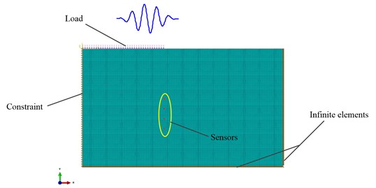
a) FE model
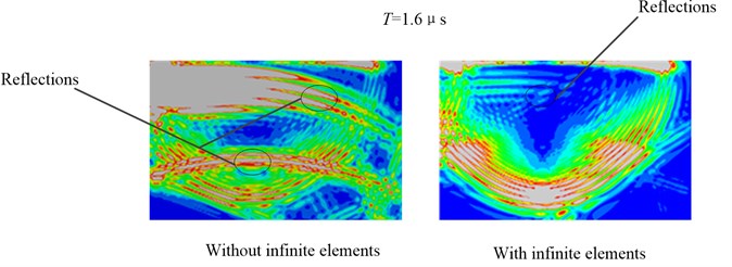
b) Propagation of AE wave mode in the plate at 1.6 μs
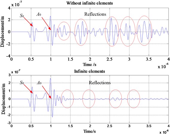
c) Vertical displacement at one sensor
Stiffness or mass proportional damping can be introduced in time or frequency domain models in most FE packages and is generally termed Rayleigh damping. We define:
where CM and CK are the mass and stiffness proportional damping coefficients.
One important point to note is that the introduction of damping decreases the value of the stable time increment when solving the model with the central difference explicit scheme [14]. A high value of CM causes a relatively small decrease in the stable increment whereas one of CK usually has a very strong effect leading to a great loss in computational efficiency (e.g. time increment divided by a thousand or more). Therefore, it is preferable to avoid using CK to define damping effect with an explicit scheme. For this work, we have only used CM for FEM studies.
Fig. 2Application to an isotropic plate with infinite elements
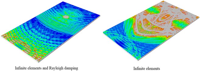
a) Wave propagation scenes at 140 μs
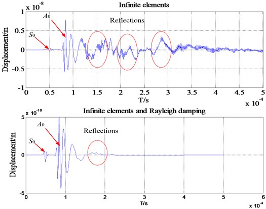
b) Comparisons between the FE models with/without infinite elements: wave packets received by one transducer
In order to examine the effect of the proposed method, two FE models are established: model with the infinite elements only, model combined the infinite elements and Rayleigh damping. Fig. 2(a) shows the wave propagation scenes which indicates that the reflections from the boundaries of the plate are extremely obvious when there are only infinite elements. Fig. 2(b) shows the wave packets received by one transducer.
The energy is proportional to the amplitude:
The amplitudes of the first arrival wave and reflection wave for A0 is shown in Fig. 3(a).
The energy reflection coefficients is calculated as:
The results are presented in Fig. 3(b) for the energy reflection coefficients via various CM. It can be seen clearly that when the CM is increased the energy reflection coefficient decreased sharply. When the value of CM reaches 5×10⁴, the energy reflection coefficient is 0.16. Moreover, with the increasing CM the energy reflection coefficient is attenuated to 0.001 when CM is 8×10⁴. However, the CM cannot be too large because the AE signal may be distorted. Therefore, the optimal CM is determined as 8×10⁴ in this AE simulation.
Fig. 3Influence of Rayleigh damping on the energy reflection coefficients
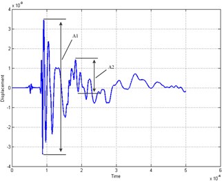
a) Definition of the energy reflection coefficient
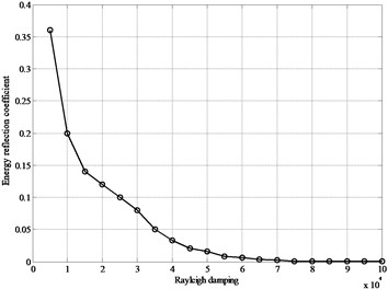
b) Energy reflection coefficients for the simulations with different CM
3. Description of simulation and source model
3.1. Description of simulation model
In order to test the effect of the non-reflecting boundary techniques, the present simulations are performed with different AE source configurations in an isotropic plate, a thin-walled cylinder, and an anisotropic plate.
Fig. 43-Dimensional model setup of simulation configuration
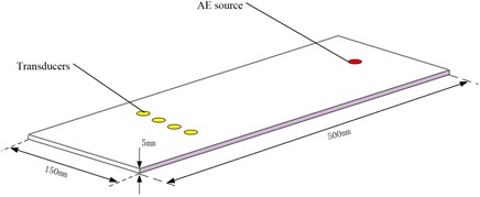
a) Plate model
b) Thin-walled cylinder
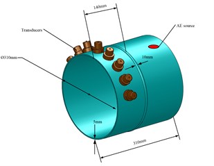
The model was simulated by FE analysis in the general three-dimensional domain implement using the commercial package ABAQUS. The respective AE signals are obtained from the surface displacements at the positions marked by transducers. The schematic of those models are shown in Fig. 4. The rectangular plate is assumed to be a specimen with 500 mm×150 mm edge length and 5 mm thickness. The model thin-walled cylinder is assumed to be 5 mm thick and is connected by a weld with 10 mm in width. The inner diameter is set to 310 mm.
3.2. Description of source model
Modeling of acoustic wave generation and propagation in plate is discussed in the following sections. AE is defined as the class of phenomena whereby transient elastic waves are generated by the rapid release of energy from a localized source or sources of damage [20]. In laboratory environment this corresponds to a Hsu-Nielsen AE source that could be generated by a pencil lead break on the surface of the structure [21]. Also an actuator was modeled that could apply this step and impulse input onto the structure [22]. Various types of sources of input can cause wave propagation in a structure. Some of these are, wave propagation due to crack growth, wave propagation due to the excitation by an actuator to study and compare baseline and damaged signals, wave propagation due to a foreign object impact like a bird hit or a torpedo hit etc. [23].
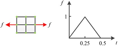
The acoustic waves in plates are generated passively using a mechanical pencil lead break input, and actively using a surface bonded piezoelectric actuator [24]. To model impact, delamination, or crack propagation, a transient excitation such as a delta or step function is needed. In order to excite an AE signal, in the following a triangular forcing function f(t) was applied (Fig. 5). In the present configuration, the total distance of the two points acting as buried dipole source was 1 mm with 1 N force magnitude [1, 4]. The goal of this model is to show dispersion effects up to a frequency, f, of 0.2 MHz.
Fig. 5The acting forces and time function of applied load
4. Application to different structures
4.1. An isotropic plate
The geometry model of the plate is shown in Fig. 2(a). The metal material was considered elastic without viscosity components. The numerical model consists of a homogeneous plate with properties of steel and specifically elasticity modulus, E= 2.09×10¹¹ N/m2; Poisson’s ratio υ= 0.3; density ρ= 7800 Kg/m3. These values lead to longitudinal and shear wave velocities of 5940 and 3230 m/s respectively. The thickness of the plate is 5 mm; its total length and width are 500 mm, 150 mm respectively. Several transducers are placed on the top surface with a separation distance of 30 mm.
In the frequency range of interest, only the zero-order symmetric mode, S0, and anti-symmetric mode, A0, are present. These two modes are selectively excited in the model by applying appropriate nodal loads. For a maximum frequency of 200 kHz, the minimum wavelength is for A0. It is given by λmin=cs/fmax=15.71 mm, considering a theoretical phase velocity of cs= 3230 m/s. In present study the value of λmin is assigned as 20 mm.
The package used in the present study, ABAQUS/EXPLICIT, uses an explicit integration based on a central difference method [25]. The stability of the numerical solution is dependent upon the temporal and the spatial resolution of the analysis.
To avoid numerical instability ABAQUS/EXPLICIT recommends a stability limit for the integration time step Δt equal to:
The maximum frequency of the dynamic problem, fmax, limits both the integration time step and the element size. A good rule is to use a minimum of 20 points per cycle at the highest frequency, that is:
The size of the finite element, le, is typically derived from the smallest wavelength to be analyzed, lmin. For a good spatial resolution 20 nodes per wavelength are normally required:
Fig. 6Comparisons between the FEM models with/without infinite elements
a) Wave propagation scenes at 1.6 μs
b) Wave packets received by one transducer
From Eq. (8), the corresponding limit on the element size is le=1 mm. According to Eq. (7), this transient problem is solved with an integration time step, Δt= 0.25 μs. The chosen excitation times investigated is 2.5 μs, which is based on the reported excitation times by Hatano et al. who used 1 μs as typical source rise time [9, 21]. In order to resolve the smallest chosen excitation time, 0.1 μs, in the time domain. The sampling rate of 5 MHz and is sufficient to resolve the observed signals frequency content in the range up to a maximal frequency of 0.2 MHz.
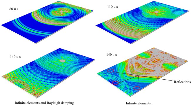
In order to test the effect of the method proposed in this paper, two FEM models are established: Model with the infinite elements only, model combined the infinite elements and Rayleigh damping. Fig. 6(a) shows the wave propagation scenes at 1.6 μs. The left wave propagation scene shows that the reflections from the boundaries of the plate are extremely obvious when there are only infinite elements. The plot on the right side is the wave propagation scene at 1.6 μs for the FE model with infinite elements and Rayleigh damping. It can be found that there is no obvious reflection coming back from the infinite elements into the area of study for these two models.
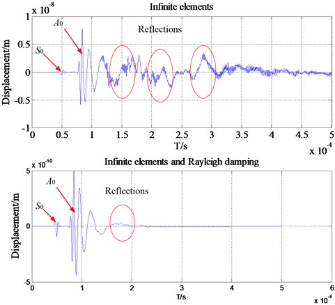
However, the reflections can still be found in the waveforms in time domain although it is relatively weak. The resulting displacements from one transducer are plotted in Fig. 6(b). It is clear that for the above waveform in time domain the reflections from the boundary are more visible than the following one. In addition, the reflections still exist for the model with infinite elements and Rayleigh damping. There is a clear discrepancy between the two monitored signals. This example confirms that infinite elements are able to remove most of the unwanted reflections, and with the help of Rayleigh damping they are suitable for high accuracy removal of unwanted reflection of bulk waves.
Fig. 7Pencil lead broken test on a steel plate
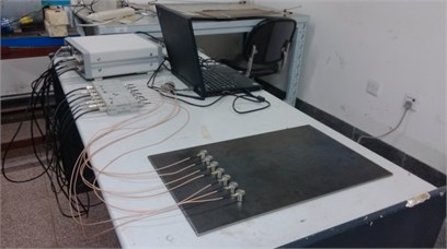
In order to verify the accuracy of this FE model, pencil lead broken test on a steel plate is carried out, as shown in Fig. 7. The sampling frequency in tests is 3 MHz. The steel plate specimen has the dimensions of 500 mm length, 150 mm width and 5 mm height. To visualize the modal composition of the AE signals the Choi-Williams transformation is calculated using the software package AGU-Vallen Wavelet [26]. The results are compared to analytical solutions of dispersion curves calculated for the respective propagation medium and distance. The resulting CWD-diagram with additionally calculated dispersion curves of is shown in Fig. 8. The signals obtained through FE simulation are transformed and the result is shown in Fig. 8(a), while the signals of pencil lead broken test is shown in Fig. 8(b). From these two figures it can be found that at low frequencies the dominance of the asymmetric mode on the surface of the plate is higher when compared to the symmetric mode. It also can be found from Fig. 8(b) that there are lots of waves with different frequencies except the A0. These should be the reflections generated when the waves are contacting the boundaries. Therefore, the simulation result will meet the experiment result if there are no reflections during pencil lead broken test.
4.2. Application to thin-walled cylinder structures
Since in the real Non-Destructive testing (NDT) there always exist some features such as welds and ribs in plate-like structures, which may cause extra coherent noise which interferes with the inspection signal. It is necessary to remove the reflection very well. This section will research the reflection removal of a thin-walled cylinder structure with a weld in middle based on the method proposed in this paper. With the same analysis method of the previous isotropic plate the FE simulation of this complex structure is carried out. Fig. 9(a) shows the wave propagation scenes at 1.6 μs. The left wave propagation scene shows that the reflections from the boundaries of the plate are extremely obvious when there are only infinite elements. The plot on the right side is the wave propagation scene at 1.6 μs for the FE model with infinite elements and Rayleigh damping. It can be found that there is no obvious reflection coming back from the infinite elements into the area of study. In addition, from Fig. 9(b) it is clear that for the above waveform in time domain the reflections from the boundary are more visible than the following one. There is a clear discrepancy between the two monitored signals. This example confirms that infinite elements are able to remove most of the unwanted reflections, and with the help of Rayleigh damping they are suitable for high accuracy removal of unwanted reflection of bulk waves.
Fig. 8WT results for an isotropic plate
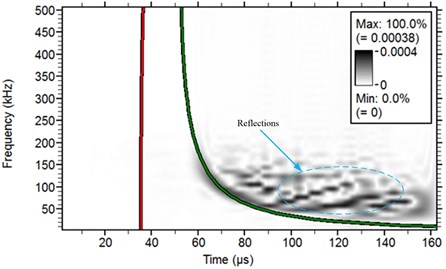
a) Result of FE simulation
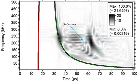
b) Result of pencil lead broken test on a steel plate
4.3. Application to a plate with filleted corner
The plate structures used in real engineering equipment are always manufactured as the shell shape. Some features may bring tackles for the wave propagation such as the filleted corner. When the direct mode waves are reaching the boundary of those features, some new mode waves may be generated. This phenomenon makes the wave propagation more complex. In order to reveal the principle of how the filleted corner influences the wave propagation, this section introduces the FEM to study the AE waves in plate structure.
4.3.1. FE mode
A plate structure with filleted corner applied in the simulation is shown in Fig. 10. The numerical model consists of a homogeneous steel plate with specifically elasticity modulus, E= 2.09×10¹¹ N/m2, Poisson’s ratio υ= 0.3, and density ρ= 7.8×10³ Kg/m3. According to the plate wave theory, the longitudinal and shear wave velocities in this plate can be calculated as 5940 and 3230 m/s respectively [26].
Fig. 11 shows the absolute displacement field for the wave propagation at 40 μsec and 80 μsec. Color scale extends from 0 (blue) to 0.1 % (red) of the maximum absolute displacement. Grey indicates out of scale (0.1 % to 100 %). It is obvious that the mode wave S0 reaches the sensor position prior to mode wave A0 because the velocity of S0 is as high as previous analysis. It also can be found that the intensity of mode wave A0 is higher than that of mode wave S0. As discussed by Gorman [27], when the pencil-lead breaks on the surface, it preferentially generates the A0 mode. And if the pencil-lead breaks on the plate edge, it excites signals with dominant S0 mode components. A similar observation was also reported by Hamstad for isotropic materials [28] and Sause for anisotropic materials [1].
Fig. 9Comparisons between the FE models with/without infinite elements
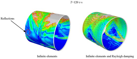
a) Wave propagation scenes at 1.6 μs
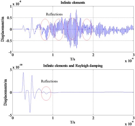
b) Wave packets received by one transducer
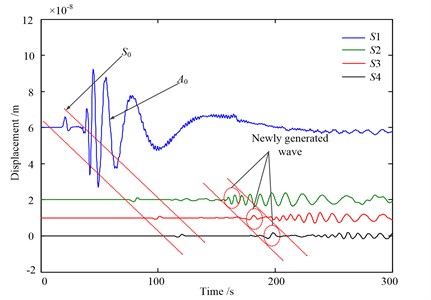
Fig. 12 shows the AE waveform detected by those four AE sensors in time domain. Some secondary waves can be found in the time-domain waveform besides the original signal. Since the velocity of secondary wave is less than the S0 wave, good separation process can be realized between this two kinds of waves. And the S0 wave is almost not affected by the secondary wave. Besides, the A0 waves detected at some points are affected by the secondary wave due to the velocity of the A0 wave is much more slowly than the S0 wave. For example, the AE signals obtained from #2 point is mixed with the secondary wave, which makes the composition of the tested wave more complicated especially the A0 wave.
The analysis results of time domain waveform indicates that when the AE waves arrive at the corner some new modal waves will be generated, thereby the complexities of the original signal are increased. According to the description in previous section, there are mainly S0 wave and A0 wave in the low frequency domain. The A0 wave may be directly affected by the secondary waves caused by the presence of rounded corners. In addition, the reflections still exist for the model with infinite elements and Rayleigh damping. There is a clear discrepancy between the two monitored signals. This example confirms that infinite elements are able to remove most of the unwanted reflections, and with the help of Rayleigh damping they are suitable for high accuracy removal of unwanted reflection of bulk waves.
Fig. 10FE mode of the plate-like structure with filleted corner
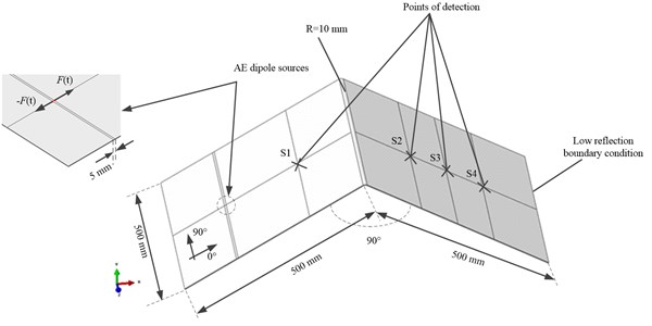
Fig. 11Absolute displacement field at two times. Color scale extends from 0 (blue) to 0.1 % (red) of the maximum absolute displacement. Grey indicates out of scale (0.1 % to 100 %)
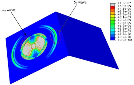
a) 40 μsec
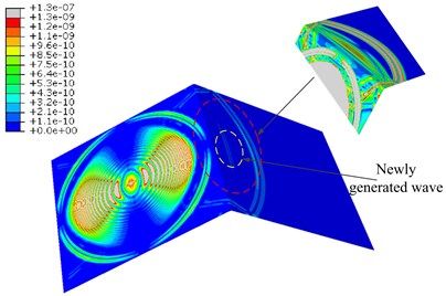
b) 80 μsec
4.4. Application to a homogeneous, anisotropic plate
The propagation of Lamb waves in an orthotropic composite structure is much more complicated than in an isotropic material. The bulk waves traveling in the structure is no more a pure mode unless traveling in the principal axis of the orthotropic material. The removal of unwanted reflection in an anisotropic plate is verified in this section of the research. Similar to the isotropic case, schematic of the carbon fiber reinforced plastics (CFRP) is shown in Fig. 13(a), and the profile of geometry is the same as the isotropic plate. Due to a lack of experimentally available values for the CFRP specimens investigated, we applied literature values from Prosser et al. to model the specimen’s elastic properties [1]. The elastic coefficients of the materials used in the simulation process are summarized as: D11, 147.1 GPa, D12, 4.11 GPa, D13, 4.11 GPa, D22, 10.59 GPa, D23, 3.09 GPa, D33, 10.59 GPa, D44, 3.75 GPa, D55, 5.96 GPa, D66, 5.97 GPa.
Fig. 12AE waveform detected by four AE sensors in time domain
Since the propagation of Lamb waves in anisotropic media like CFRP is more complex than for isotropic media, propagation of AE wave mode in CFRP plate should be analyzed detail. Propagation of AE wave mode in CFRP plate with the infinite elements and Rayleigh damping at three distinct times is shown in Fig. 13(b). And there are no visible reflections from the boundaries whether the Rayleigh damping is assigned or not from the wave propagation scenes only. However, the reflections can still be found in the waveforms in time domain although it is relatively weak. The resulting displacements from one transducer are plotted in Fig. 13(c). It is clear that for the above waveform in time domain the reflections from the boundary are more visible than the following one. In addition, the reflections still exist for the model with infinite elements and Rayleigh damping. There is a clear discrepancy between the two monitored signals. This example confirms that infinite elements are able to remove most of the unwanted reflections, and with the help of Rayleigh damping they are suitable for high accuracy removal of unwanted reflection of bulk waves.
5. Conclusions
In this study, a new modeling method of plate waves by investigating the removal of unwanted reflections from the boundaries of the waveguides including plate and thin-walled cylinder structures has been presented. The principles of these techniques were described. Analytical models to facilitate the efficient and reliable design of FE models to exploit them were developed.
To validate the potential of this method for engineering applications, pencil lead broken tests on a steel plate are performed. Experimental results show that at low frequencies the dominance of the asymmetric mode on the surface of the plate is higher when compared to the symmetric mode. The stiffness and mass proportional damping are introduced in the simulation. The removal effect is validated by serial simulations with different AE source configurations in isotropic and anisotropic plate. The results of this study clearly illustrate the effectiveness of using the FE method to model AE wave propagation problems and high accuracy removal of unwanted reflection can be realized by the infinite elements with appropriate damping.
Fig. 13Comparisons between the FE models with/without infinite elements
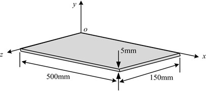
a) Geometric model of the CFRP plate
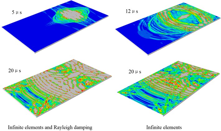
b) Propagation of AE wave mode in CFRP plate with the infinite elements and Rayleigh damping at three distinct times and wave propagation scenes at 20 μs for the model with infinite elements only
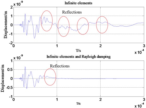
c) Wave packets received by one transducer
References
-
Sause M. G. R., Horn S. Simulation of acoustic emission in planar carbon fiber reinforced plastic specimens. Journal of Nondestructive Evaluation, Vol. 29, 2010, p. 123-142.
-
Hamstad M. A., O’Gallagher A., Gary J. A wavelet transform applied to acoustic emission signals. Part 1: source identification. Journal of Acoustic Emission, Vol. 20, 2002, p. 39-61.
-
Hamstad M. A., O’Gallagher A., Gary J. Modeling of buried acoustic emission monopole and dipole sources with a finite element technique. Journal of Acoustic Emission, Vol. 17, 1999, p. 97-110.
-
Moser F., Jacobs L. J., Qu J. Modeling elastic wave propagation in waveguides with the finite element method. NDT & E International, Vol. 32, 1999, p. 225-234.
-
Fan Z., Lowe M. J. S., Castaings M., Bacon C. Torsional waves propagation along a waveguide of arbitrary cross section immersed in a perfect fluid. Journal of the Acoustical Society of America, Vol. 124, 2008, p. 2002-2010.
-
Liu G., Quek J. S. A non-reflecting boundary for analysing wave propagation using the finite element method. Finite Elements in Analysis and Design, Vol. 39, 2003, p. 403-417.
-
Givoli D. High-order local non-reflecting boundary conditions: a review. Wave Motion, Vol. 39, 2004, p. 319-326.
-
Bettess P. Infinite Elements. Penshaw Press, 1992.
-
Givoli D., Keller J. B. Non-reflecting boundary conditions for elastic waves. Wave Motion, Vol. 12, 1990, p. 261-279.
-
Osinov V. A. Non-reflecting boundary conditions for plane waves in anisotropic elasticity and poroelasticity. Acta Mechanica, Vol. 223, 2012, p. 593-607.
-
Castaings M., Bacon C., Hosten B., Predoi M. V. Finite element predictions for the dynamic response of thermo-viscoelastic material structures. Journal of the Acoustical Society of America, Vol. 115, 2004, p. 1125-1133.
-
Sochacki J., Kubichek R., George J., et al. Absorbing boundary condition and surface waves. Geophysics, Vol. 52, 1987, p. 60-71.
-
Mickael B. D. Efficient Finite Element Modeling of Ultrasound Waves in Elastic Media. Ph.D. Thesis, Imperial College London, 2004.
-
Berenger J. P. A perfectly matched layer for the absorption of electromagnetic waves. Journal of Computational Physics, Vol. 114, 1994, p. 185-200.
-
COMSOL User’s Guide version 3.2. www.femlab.com, 2006.
-
Castaings M., Bacon C. Finite Element modeling of torsional wave modes along pipes with absorbing materials. Journal of the Acoustical Society of America, Vol. 119, 2006, p. 3741-3751.
-
ABAQUS v12.1 Analysis User’s Manual. 2012.
-
Basu U., Chopra A. K. Perfectly matched layers for time-harmonic elastodynamics of unbounded domains: theory and finite-element implementation. Computer Methods in Applied Mechanics and Engineering, Vol. 192, 2003, p. 1337-1375.
-
Collino F., Tsogka C. Application of the PML Absorbing Layer Model to the Linear Elastodynamic Problem in Anisotropic Heterogeneous Media. Technical Report 3471, INRIA, 1998.
-
Wells R., Hamstad M. A., Mukherjee A. K. On the origin of the first peak of acoustic emission in 7075 aluminum alloy. Journal of Materials Science, Vol. 18, 1983, p. 1015-1020.
-
Dunegan H. L. An alternative to pencil lead breaks for simulation of acoustic emission signal sources. The DECI Report, 2000.
-
Ghoshal A., Martin W. N., Schulz M. J., Chattopadhyay A., Prosser W. H. Simulation of Asymmetric Lamb waves for Sensing and Actuation in Plates. Shock and Vibration Journal, Vol. 2, 2005, p. 243-271.
-
Goutham R. K. A Structural Neural System for Health Monitoring of Structures. Ph.D. Thesis, University of Cincinnati, 2006.
-
Berenger J. P. Simulation of asymmetric Lamb waves for sensing and actuation in plates. Journal of Shock and Vibration, Vol. 12, 2005, p. 243-271.
-
Ivan B., Francesco L. S., Mahmood F., et al. Modeling guided wave propagation with application to the long-range defect detection in railroad tracks. NDT & E International, Vol. 38, 2005, p. 325-334.
-
AGU-Vallen Wavelet. Vallen Systeme GmbH, Munich, Germany, Aoyama Gakuin University, 2010.
-
Gorman M. R. Plate wave acoustic emission. Journal of the Acoustical Society of America, Vol. 90, 1991, p. 358-364.
-
Hamstad M. A., Gallagher A. O., Gary J. Effects of lateral plate dimensions on acoustic emission signals from dipole sources. Journal of Acoustic Emission, Vol. 19, 2001, p. 258-274.
About this article
This work was finically supported by the National Science Foundation of China (Grant No. 51105018). Special thanks are due to the editor Prof. Minvydas Ragulskis and Martynas Vaidelys in typesetting Department of this article for many essential remarks with respect to the article.
