Abstract
The primary resonance of a simply supported rotating composite shafts with geometrical nonlineary is studied. The composite shaft is modeled as a thin-walled Euler-Bernoulli beam. A variational-asymptotical method (VAM) applied to anisotropic thin-walled closed-cross-sectional beams is used to describe the displacement and strain fields of the composite shafts. The geometrical nonlineary is considered in the relationships of strain and displacement of the shaft. The nonlinear extensional-bending-torsional equations of motion for the composite shaft are derived by using the Hamilton principle. In order to emphatically study nonlinear transverse bending vibration, the effects of extensional and torsional deformations are ignored. By means of the method of multiple scales the approximation solution of primary resonance of transverse bending vibration is obtained. The Galerkin method is employed to reduce the governing equations to the ordinary differential equations. By using fourth-order Runge-Kutta method the time histories, phase diagrams and power spectrums are plotted. The study shows the effect of the external damping, ply angle, eccentricity, ratios of length over radius, ratios of radius over thickness and rotating speed on nonlinear dynamic behavior of the shaft. Specifically, the numerical simulation results show that the shaft exhibits the complex dynamic behavior including periodic, quasi-periodic and chaotic motion.
1. Introduction
Shaft is the primary component of rotating machaines which are used for transmission of power and energy transition. Accurate dynamical analysis of rotating shaft is necessary for optimizing the rotordynamics of rotating machines. The conventional shaft dynamical studies were confined to critical speeds, natural freqencies and threshold of stability and linear assumption was often employed in mathematical modeling. The importance of application of nonlinear models which are due to the large amplitudes of vibration has increased along with current demand for investigation of the nonlinear phenomena of long driveshafts of a helicopter or automotive using composite materials. Melanson and Zu [1] presented vibration analysis of an internally damped rotating shaft by using Timoshenko shaft theory. Shabaneh and Zu studied [2] free and forced vibrations of a rotating shaft-disk system with linear elastic bearings. Sheu and Yang [3] develpoed an analytical solution of the critical speeds and mode shapes of a rotating Rayleigh shaft with six boundary conditions. Kim et al. [4] considered the free vibrations of a rotating tapered composite Timoshenko shaft. Zinberg and Symonds [5] proposed Equivalent Modulus Beam Theory-EMBT to formulate the dynamical equations of composite driveshaft. Singh and Gupta [6] developed a layerwise beam theory based on layerwise shell theory in order to predict free vibration behavior of shafts with an unsymmetric stacking sequence. Song et al. [7] evaluated the influence of conservative and gyroscopic forces on vibration and the stability of a circular cross-section shaft. Yamamoto and Ishida [8] showed that in some specific conditions, internal damping may cause instability in the rotating shaft. In fact, the internal damping will reduce the whirling motion when the rotating speed of the shaft is kept below the critical speed. Conversely, internal damping will destabilize the whirling motion if the rotating speed of the shaft is above the critical speed. However, the nonlinear vibration of shaft in the supercritical range should be described by nonlinear dynamical model. Shaw and Shaw [9] presented the nonlinear vibration study for a rotating Euler shaft. The shaft has been modelled based on the Von Kármán non-linearity, simply supported at both ends. In addition, the same authors [10] studied the nonlinear dynamic response of an unbalanced rotating shaft with internal damping. Kurnik [11] used the bifurcation theory to evaluate the stability and self-excited supercritical whirling motion of rotating shaft. Ji and Zu [12] analyzed the free and forced vibration of nonlinear rotor-bearing systems using the method of multiple scales. Hosseini and Khadem [13-14] considered free vibrations and combination resonances of the rotating shaft with nonlinear curvature and inertia using the method of multiple scales. Although various works for studing nonlinear dynamics of rotating metallic shaft have already been presented as shown in the above-mentioned literatures, however, no studies deal with nonlinear dynamics of rotating composite shafts have been reported yet.
In the present work, nonlinear resonance of an unbalanced rotating composite shafts with simply supported condition is investigated. VAM [15] applied to anisotropic thin-walled closed-cross-sectional beams is used to model the composite shaft and the Von Kármán non-linearity is included. The nonlinear equations of motion for the rotating composite thin-walled shaft are derived by using the Hamilton principle. The effects of external viscous damping and unbalance mass are also considered. The multiple scales method is employed to obtain the approximation solution of primary response of transverse bending vibration. The Galerkin method is used to reduce equations of motion into the ordinary differential equations. Time histories, phase diagrams and power spectrums of the response are presented by using the time-integration method. The effects of various parameter including the external damping, ply angle, eccentricity, ratios of length over radius, ratios of radius over thickness and rotating speed on nonlinear dynamic behavior of the shaft are investigated.
2. Equation of motion
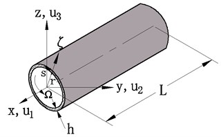
The slender thin-walled composite shaft subjected to a rotation about its longitudinal x-axis at a constant rotating speed Ω is shown in Fig. 1. The length, wall thickness and radius of the shaft are denoted by L, h and r, respectively. The inertial reference system (X,Y,Z) and the rotating reference system (x,y,z) are used to describe the motion of the shaft. This two sets of co-ordinate systems have the common origin O which is located in the geometric center. The unit vectors (I,J,K) and (i,j,k) associated with (X,Y,Z) and (x,y,z) are defined, respectively. A local coordinate system (ς,s,x) is also defined, where ς and s are the circuferential and thickness co-ordinates, respectively.
Fig. 1Thin-walled composite shaft of a circular cross section
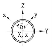
The equations of motion of the composite rotor can be derived by employing the following Hamilton principle:
here the kinetic T and the strain U can be computed as:
where and are stress components, and are strain components, is the velocity vectors for the deformed shaft, is the mass density, , and are the displacements at material point along the shaft cross-section, dot indicates the time derivative of the variable. The displacement and strain field can be described by the composite thin-walled beam theory based on VAM [15]. Using the Von Kármán non-linearity in the strain equations, one has [16]:
where is the classical torsional-related warping, ( 1, 2, 3) are extension, torsion, and bending warping function [15], respectively. is the twist angle. The primes in Eq. (4) denote differentiation with respect to .
The constitutive equations of a lamina layer can be expressed as:
where are transformed reduced stiffnesses.
Substituting Eqs. (2) and Eq. (3) into Eq. (1), the following governing equations can be obtained:
where:
Here, , , and in Eqs. (6) are the generalized cross-sectional force and moments. Its expressions are given in Ref. [16].
Eqs. (6) are nonlinear differential equations of motion associated with the extension-bending-bending-torsional vibration of a composite shaft. Substitution of , , and into the Eqs. (6) yields the equations of motion in the displacements , , and the twist angle . The emphasis of the present study is placed on only the problem involving the bending-bending coupling. In order to obtain the approximate solution of the nonlinear flexural vibration of the composite shaft, the effects of extensional and torsional deformation are neglected in the second and third equation of Eqs. (6). In addition, one laminated composite configuration: the circumferentially uniform stiffness configuration (CUS) [17], is also used in the following formulation.
Moreover, if the inertia reference system is used and the effect of external daming and unbalance mass is considered, nonlinear vibration equations with bending-bending coupling of a composite shaft can be written as:
where, is external daming parameter, and is the eccentricity of the shaft cross-section:
and paramter , and are defined in terms of the axial stiffness coefficients [15].
By adopting the following dimensionless quantities, one can derive the equations of motion in the complex form as:
where is the complex conjugate of . For simplicity, the stars in the above dimensionless quantities have been omitted.
3. Approximate solution procedure
3.1. The multiple scales method
In Eq. (10), the transformation , , , , is used. Where is a small parameter.
Using this transformation, the following equation can be obtained:
The solution of Eq. (11) is assumed in the form:
where, , .
Using the chain rule, one has:
where , ( 0, 1, 2,…,).
Substituting Eq. (12) into Eq. (11) and letting the coefficients of the same power of equal zero, the following two equations can be obtained:
The solution of Eq. (14) can be written as:
To order to obtain the primary resonance solution of Eq. (15), we use , where is a natural frequency of forward whirling motion of the composite shaft, is a detuning parameter.
Substituting Eq. (16) into Eq. (15), one has:
here:
The solvability conditions of Eq. (17) can be expressed as following as:
Substitution of Eq. (18) into Eq. (19) gives:
In order to solve Eq. (20), is assumed in the form , where is amplitude of the forward whirling motion.
Substituting the expression of into Eq. (20) and letting the real and imaginary parts of the resulting equation equal zero, one has:
where .
Let and in Eqs. (21), the steady state solutions and can be achieved.
By reducing the phase from the resulting equations, the following relationship of amplitude-frequency can be obtained:
3.2. The Galerkin method and time integration
The Galerkin method is employed to find approximate solution in the form:
where is the mode shape functions, which satisfy simply supported condition of the shaft. Under this boundary condition the mode shape functions can be expressed by:
Using the single mode approximate and substituting Eq. (23) into Eq. (8), the following nonlinear ordinary differential equations can be derived:
where:
In the present work, the fourth order Runge-Kutta method is used to integrate Eq. (25) in order to obtain the steady state response of the composite shaft under the action of unbalance mass.
4. Numerical results
The numerical analysis is performed for the composite shaft whose geometrical properties are: 1.2 m, 0.127 m, 0.0635 mm. The composite shaft is considered to be graphite-epoxy with stacking sequence . The material characterististics of the shaft are: 206.8 GPa, 5.17 GPa, 3.1 GPa, 2.55 GPa, 0.00625, 0.25, 1528.15 kg/m3.
4.1. Frequency response behavior
In Figs. 2-6, the frequency response curves of the composite shaft are presented for various parameters including , ,, and . From figures it can be seen that these curves are bent toward the axis direction due to the effect of cubic order geometrical nonlinearity. So the effective nonlinearity of shaft is of hardening spring type. For a given value of detuning parameter , either single stable solution or three solutions, including one unstable and two stable can be obtained. As seen in these figures, jump phenomenon occurs. Fig. 2 shows that the increase of the mass unbalance can cause the amplitude of the response to increase. Fig. 3 shows that the amplitude of the response of the composite shaft is decreased with the increase of the external damping coefficient. Fig. 4 presents the effect of the ply angle. The results show that the response curves bend more stongly towards the axis direction as the ply angle increases. In addition, it is seen that the increase of the ply angle can cause a significant increase of the amplitude of the shaft. Figs. 5 and 6 present the effect of ratios of length over radius and ratios of radius over thickness on the amplitude of the response, respectively. In these figures, it can be seen obviously that ratios of length over radius has much more influence compared with ratios of radius over thickness.
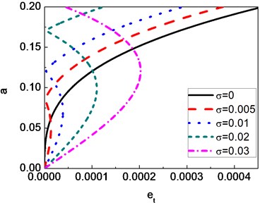
Fig. 7 presents the variation of amplitude with for various . It can be seen that when the shaft is balanced ( 0), single trivial solution exists. In addtion, the results show that the shaft has a single stable solution for case of . However, for some value of 0, the multi-valued curves can be obtained.
Fig. 2Frequency-response curves of a composite shaft for different eccentricity values (c= 0.6 Ns/m, θ= 60°)
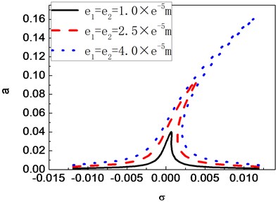
Fig. 3Frequency-response curves of a composite shaft for different damping coefficients, first mode (e1=e2= 1×10⁻⁵ m, θ= 60°)
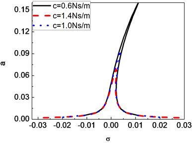
Fig. 4Frequency-response curves of a composite shaft for different ply angles, first mode (e1=e2= 4×10⁻⁵ m, c= 0.6 Ns/m)
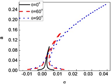
Fig. 5Frequency-response curves of a composite shaft for different ratios of length over radius, first mode (e1=e2= 4×10⁻⁵ m, c= 0.6 Ns/m, θ= 60°)
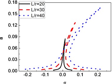
Fig. 6Frequency-response curves of a composite shaft for ratios of radius over thickness, first mode (e1=e2= 4×10⁻⁵ m, c= 0.6 Ns/m, θ= 60°)
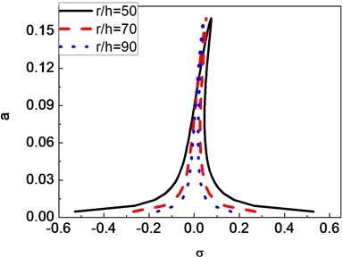
Fig. 7Amplitude versus eccentricity of a composite shaft for different detuning parameter values
4.2. Time response behavior
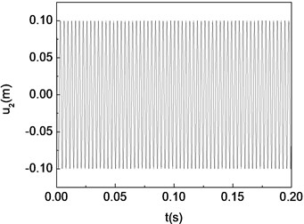
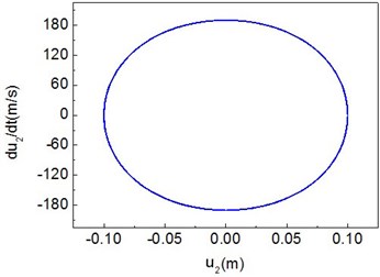
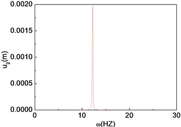
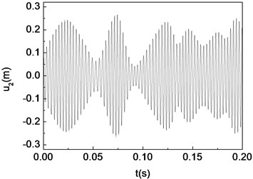
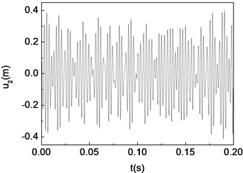
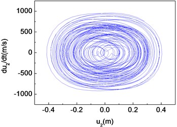
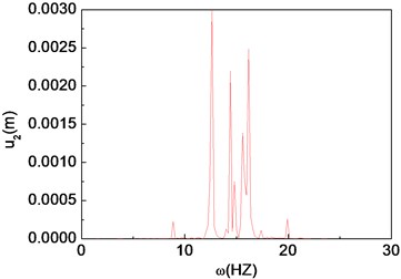
The unbalance responses for the mid-span of the shaft are calculated by integrating Eq. (29) using the fourth order Runge-Kutta method. Figs. 8-10 present the time histories, phase diagrams and power spectrums of the shaft corresponding to 5×10⁻⁷ m, 5×10⁻³ m and 5×10⁻¹ m, respectively. The resulting figures are plotted for 60°, 2000 rad/s and 0. From these figures it can be seen that single periodic motion, quasi-periodic and chaotic motion appear, when the eccentricity 5×10⁻⁷ m, 5×10⁻³ m and 5×10⁻¹ m, respectively.
Fig. 8Period-one motion of the composite shaft (e1= 5×10⁻⁷ m)
a) Time history
b) Phase diagram
c) Power spectrum
Fig. 9Quasi-periodic motion of the composite shaft (e1= 5×10⁻⁵ m)
a) Time history
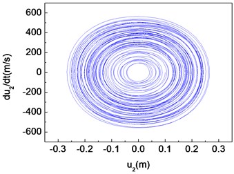
b) Phase diagram
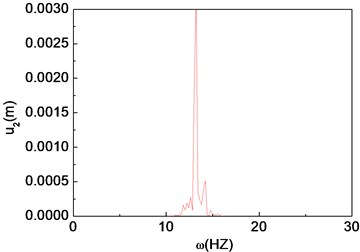
c) Power spectrum
Fig. 10Chaotic motion of the composite shaft (e1= 5×10⁻³ m)
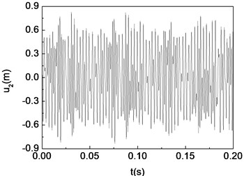
a) Time history
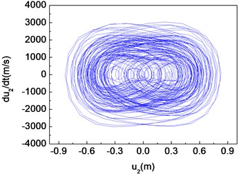
b) Phase diagram
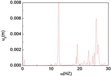
c) Power spectrum
Fig. 11Period-one motion of the composite shaft (Ω= 100 rad/s)
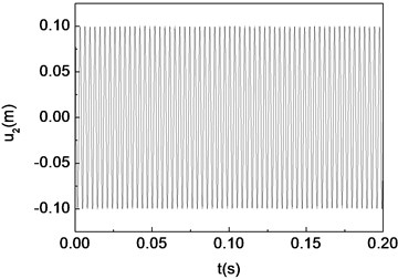
a) Time history
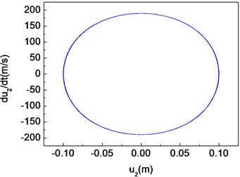
b) Phase diagram
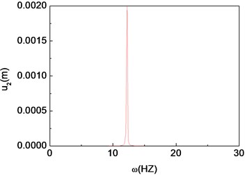
c) Power spectrum
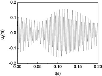
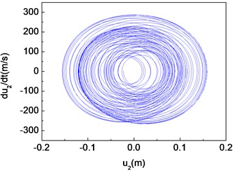
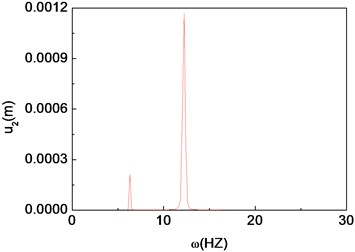
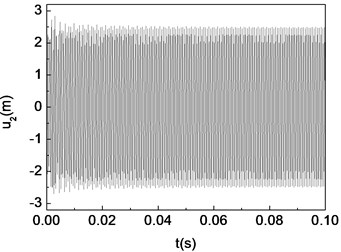
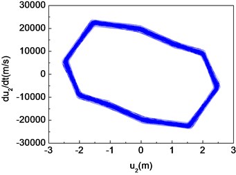
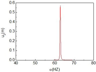
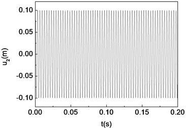
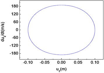
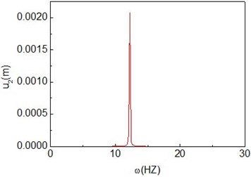
Figs. 11-15 present the effect of varying the rotating speed on the dynamical behavior of the shaft. It can be observed that by increasing the rotating speed, the system response evolves in succession from single periodic motion to quasi-periodic motion, chaotic motion, quasi-periodic motion then back to single periodic motion. As shown previously from Figs. 2-6, the frequency response curves have stable and unstable branches, thus bifurcation will occur. The quasi-periodic motion is one of the route to chaotic vibration. It is because of Hopf bifurcation that can cause quasi-periodic motion to appear [10].
Fig. 12Quasi-periodic motion of the composite shaft (Ω= 1000 rad/s)
a) Time history
b) Phase diagram
c) Power spectrum
Fig. 13Chaotic motion of the composite shaft (Ω= 2000 rad/s)
a) Time history
b) Phase diagram
c) Power spectrum
Fig. 14Quasi-periodic motion of the composite shaft (Ω= 9000 rad/s)
a) Time history
b) Phase diagram
c) Power spectrum
Fig. 15Period-one motion of the composite shaft (Ω= 10000 rad/s)
a) Time history
b) Phase diagram
c) Power spectrum
5. Conclusion
A dynamical mode for the rotating composite thin-walled shaft with geometrical non-linearity has been developed. The emphasis is mainly on the primary resonances of transverse bending vibration, in which the effects of extensional deformation and torsional deformation are ignored. The numerical simulations are carried out using two method, i.e. multiple scales method and direct time-integration method. Frequency response, time histories, phase diagrams and power spectrums have been obtained to investigate the effect of various paramters upon motion state of the system.
From the present analysis and the numerical results, the following main conclusions can be drawn:
1) The rotating composite thin-walled shaft with geometrical non-linearity exhibits a typical behavior of hardening spring, i.e. the nonlinear frequencies increase as the amplitude increases. And multi-valued response curves and jump phenomenon can be observed.
2) External damping can suppress the amplitude of the response of the shaft effectively. Ply angle, eccentricity and ratios of length over radius significantly influence the shape of resonant curves and the effect of ratios of radius over thickness is seem not significant.
3) The eccentricity and rotating speed have a significant influence on the stability of the shaft. With the rotating speed or eccentricity increasing, the system presents the existence of a complex dynamic behavior including periodic, quasi-periodic and chaotic motion.
References
-
Melanson J., Zu J. W. Free vbration and stability analysis of internally damped rotating shafts with general boundary conditions. ASME Journal of Vibration and Acoustics, Vol. 120, 1998, p. 776-783.
-
Shabaneh N. H., Zu J. W. Dynamic analysis of rotor-shaft systems with viscoelastically supported bearings. Mechanism and Machine Theory, Vol. 35, 2000, p. 1313-1330.
-
Sheu G. J., Yang S. M. Dynamic analysis of a spinning Rayleigh beam. International Journal of Mechanical Science, Vol. 47, 2005, p. 157-169.
-
Kim W., Argento A., Scott R. A. Free vibration of a rotating tapered composite Timoshenko shaft. Journal of Sound and Vibration, Vol. 226, 1999, p. 125-147.
-
Zinberg H., Symonds M. F. The development of an advanced composite tail rotor drive shaft. Presented at the 26th Annual National Forum of the American Helicopter Society, June, Washington, DC, 1970.
-
Singh S. P., Gupta K. Composite shaft rotordynamic analysis using a layer wise theory. Journal of Sound and Vibration, Vol. 191, Issue 5, 1996, p. 739-756.
-
Song O., Jeong N.-H., Librescu L. Implication of conservative and gyroscopic forces on vibration and stability of an elastically tailored rotating shaft modeled as a composite thin-walled beam. Journal of Acoustics of Socity of American, Vol. 109, Issue 31, 2001, p. 972-981.
-
Yamamoto T., Ishida Y. Linear and Nonlinear Rotordynamics. John Wiley and Sons, 2001.
-
Shaw J., Shaw S. W. Instabilities and bifurcations in a rotating shaft. Journal of Sound and Vibration, Vol. 132, 1989, p. 227-244.
-
Shaw J., Shaw S. W. Non-linear resonance of an unbalanced rotating shaft with internal damping. Journal of Sound and Vibration, Vol. 147, 1991, p. 435-451.
-
Kurnik W. Stability and bifurcation analysis of a nonlinear transversally loaded rotating shaft. Nonlinear Dynamics, Vol. 5, 1994, p. 39-52.
-
Ji Z., Zu J. W. Method of multiple scales for vibration analysis of rotor-shaft systems with non-linear bearing pedestal model. Journal of Sound and Vibration, Vol. 218, 1998, p. 293-305.
-
Hosseini S. A. A., Khadem S. E. Free vibrations analysis of a rotating shaft with nonlinearities in curvature and inertia. Mechanism and Machine Theory, Vol. 44, p. 272-288.
-
Hosseini S. A. A., Khadem S. E. Combination resonances in a rotating shaft. Mechanism and Machine Theory, Vol. 44, 2009, p. 1535-1547.
-
Berdichevsky V., Armanios E., Badir A. Theory of anistropic thin-walled closed-cross-section beams. Composites Engineering, Vol. 2, 1992, p. 411-432.
-
Ren Yongsheng, Dai Qiyi, Sun Binglei, et al. Free vibration of a rotating composite thin-walled beam with large deformation. Journal of Vibration and Shock, Vol. 32, Issue 14, 2013, p. 139-147, (in Chinese).
-
Smith E. C., Chopra I. Formulation and evaluation of an analytical model for composite box-beams. Journal of American Helicopter Society, Vol. 36, Issue 3, 1991, p. 23-25.
About this article
The research is funded by the National Natural Science Foundation of China (Grant No. 11272190) and Shandong Provincial Natural Science Foundation of China (Grant No. ZR2011EEM031).
