Abstract
In view of statically indeterminate structures of the decanter centrifuge, an iteration calculation model of nonlinear bearing stiffness is built innovatively. Based on gear meshing stiffness, material and lubricant film damping, coupled dual-rotors vibration model of screw-differential mechanism-bowl is constructed using solid elements. Applying ANSYS modal analysis, critical speeds along with vibration modes of dual-rotors and single-rotor are simulated, and the impacts of the differential mechanism and single-rotor modal on dual-rotors modal are obtained. Built on the harmonic response analysis, the results indicate that the system responses differently for the different rotors by manipulating the dynamic responses of the centrifuge under single rotor unbalance excitation. On the basis of transient structural analysis, beat vibration characteristics of dual-rotors system with little rotation speed difference are obtained, and a conclusion of the system responses separately for the unbalance mass of different rotors at a low rotating speed is acquired. The models and methods adopted in simulation are proved to be reasonable and feasible by experiment. The results have certain significance for the design and the dynamic balancing technique of the decanter centrifuge.
1. Introduction
The horizontal decanter centrifuge is widely used in many areas such as the chemical, environmental protection, pharmacy industry with the advantages of continuous operation, high separation factor and large production capacity. As a kind of rotary machine with dual-rotors, the inner rotor of the centrifuge is the screw and outer rotor is the bowl. The screw is supported on the bowl by intermediate bearings while the bowl is supported on the bearing block by the main bearings. With slightly different rotating speeds, the vibration characteristic of the system is the coupling effect of the double rotors, similar to the structure of aero-engine dual-rotors system.
A series of researches on dynamic characteristics of the aero-engine were conducted during the past 40 years. Using the matrix transfer method and considering nonlinear effects of the damper, critical speed, mode shape, and unbalance response are determined numerically by D. H. Hibner and E. J. Gunter [1-4] in the 1970s and 1980s. In 1980, D. A. Glasgow and H. D. Nelson presented a method of component mode synthesis for the analysis of multi-shaft rotor-bearings systems, by which damped whirl speed and stability were analyzed [5]. By developing an extended transfer matrix procedure in complex variables, K. Guptak studied the unbalance response of a dual rotor system theoretically and experimentally [6]. A new integration scheme which can reduces computation time greatly for blade loss simulation including thermal growth effects for a dual-rotor gas turbine engine supported on bearing and squeeze film damper was presented by Sun Guang young et al. [7]. Hai Pham Minh et al. also developed a novel implicit “impulsive receptance method” (IRM) for the time domain analysis of dual-rotors system. By this method, a much more physically accurate solution is achievable within a short timeframe [8]. Recently through simplifying the rotors as beam elements, the vibration modeling of dual-rotors aero-engine was conducted by Hsiao Wei Chiang and Chen Guo et al., a series of conclusions including critical speed, strain energy distribution and unbalance response were obtained [9, 10].
Although an in-depth study of aero engine has been conducted, researches on the vibration characteristics of the decanter centrifuge are limited, which mainly concentrated on dynamic balancing methods and numerical simulations. Zeng S., Tan L. F. et al carried out a series of experimental researches to study the unbalance identification and field balancing of decanter centrifuge [11, 12] while Zhang Z. X. proposed a non-whole beat correlation method for the identification of unbalance response, which was proved to be effective by experiments [13]. Li X. L., Zhang Z. X., He S. Z. made numerical analysis of a synchronous dual-rotor’s steady-state response by finite element method and obtained the differences of vibration response under synchronous and asynchronous conditions of the rotors [14].
As we can see, when calculating the dynamic characteristics of the dual rotor system, the rotors are always simplified as beam and mass elements. It’s a difficult task to acquire the mass and stiffness characteristics of the elements which is not so practical in the engineering practice. And meanwhile, few attentions have been paid to the contribution of a single rotor vibration to the whole dual-rotors system. Using 3D model, this paper presents the finite element modeling method of the decanter centrifuge and studies on the coupling effects of the dual-rotors system.
2. The finite element model of a decanter centrifuge-generator system
Considering the nonlinear effects of the damper, 3D model of a decanter centrifuge is built by ANSYS (Canonsburg, PA, USA) in this part.
2.1. Geometric model
The decanter centrifuge is mainly composed of three parts: the bowl, the screw and the differential mechanism, which is shown in Fig. 1. Due to the complexity of the decanter centrifuge structure, the structure is simplified in the process of modeling as below:
a) Taking no account of the bolt connection of the rotors, different components connected by bolt are considered as a whole part.
b) The spiral vane is asymmetric and makes little contribution to the stiffness of the screw. While the unbalance mass caused by the spiral vane is balanced before assemblage, the asymmetric vane is simplified as symmetric point mass.
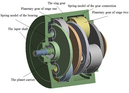
c) The geometric model of the decanter centrifuge is shown in Fig. 2, and the differential mechanism in the model is two-stage planetary gear differential. Bearings on the machine and the gears in the differential are simplified as spring connections, as shown in Fig. 3.
Fig. 1Structure diagram of the decanter centrifuge
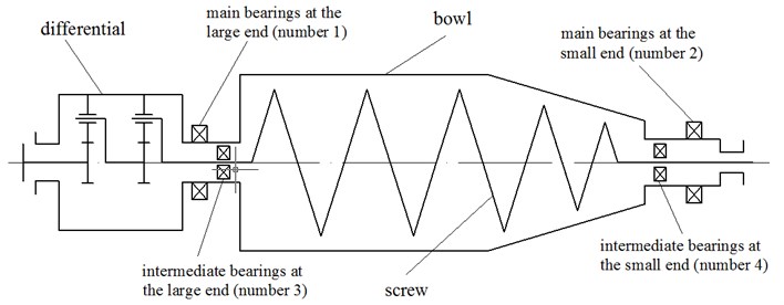
Fig. 2Geometric model of the decanter centrifuge
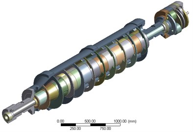
Fig. 3Structure schematic of the differential mechanism
2.2. Material properties
Material properties of the bowl, the screw and the differential mechanism used in the analysis are listed in Table 1.
Table 1Material properties
Item | Young’s modulus | Poisson’s ratio | Density |
Bowl | 190 GPa | 0.3 | 7880 kg/m3 |
Screw | 200 GPa | 0.3 | 8000 kg/m3 |
Differential | 210 GPa | 0.269 | 7850 kg/m3 |
2.3. Bearing stiffness and damping
2.3.1. Bearing stiffness
The bearing stiffness is calculated by the semi empirical formula method [15] based on Hertz theory as shown in Eq. (1) and Eq. (2):
The whole structure composed of inner and outer rotors which is connected by intermediate bearings, differential gear and bearings is statically indeterminate structure. As a result, distributions of the bearing forces are closely related to the radial deformation, yet the radial deformation is determined by bearing stiffness which is closely related to bearing forces. Because of the complex relationship among bearing stiffness, forces and deformation, the bearing stiffness can’t be calculated at a time. An iterative method is used to calculate bearing stiffness in this paper, instead.
Based on combi214 element of ANSYS, considering the load of gravity, the process of the nonlinear iterative stiffness-force-deformation method is shown as below:
Assuming the initial bearing stiffness as and applying finite element static analysis, calculate the initial value of the bearing deformation under gravity.
According to , Eq. (1) and Eq. (2), calculate the bearing stiffness .
Based on , by structural static analysis, get the bearing deformation .
Repeat the process of II and III until the value of satisfies the inequality , where is the minimum iteration error whose value is set to be 1.
In the process, , , , , , and are vectors which consist of the values of all the bearings.
2.3.2. Bearing damping
The theory used to build the model calculating the bearing damping is the comprehensive damping method which is established through analysis on load, deformation and implementation of Reynolds equation including the influences of both lubrication and elastic deformation of roller and raceways [16]. According to the theory, the damping of main bearings and intermediate bearings are listed in Eq. (3)-Eq. (6).
Main bearings at the large end:
Main bearings at the small end:
Intermediate bearings at the large end:
Intermediate bearings at the small end:
2.4. Gear meshing stiffness
Without considering the instantaneous stiffness caused by instantaneous meshing tooth numbers, the model adopt to ISO 6336-1-1996 is used to calculate cylindrical gear stiffness which can be applied to spur gear and helical gear [17]. The model is based on theoretical studies of the elastic behavior of disc spur gear with basic rack profile ( 20°, , , ). The concrete calculation formulas of the model are as Eq. (7)-Eq. (9).
Meshing stiffness of single pair gear :
Comprehensive meshing stiffness :
Total meshing stiffness :
3. Critical speed
3.1. Critical speed and mode shape without differential
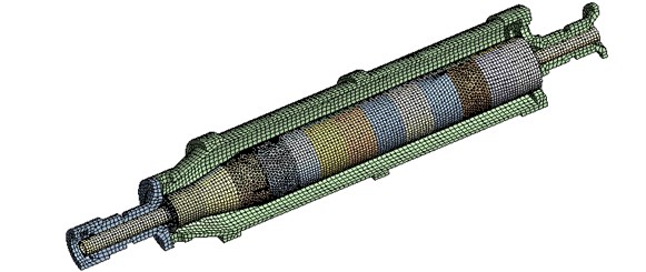
ANSYS modal analysis is adopted to calculate the critical speed and mode shape of the system. Before the modal analysis, bearing stiffness is determined first. In order to get the bearing stiffness, nonlinear static analysis applying the iterative stiffness-force-deformation method under the load of gravity using ANSYS is first conducted. The element used in the analysis is Solid186 and the meshing diagram is shown as Fig. 4. The number of nodes is 208568 and the number of elements is 65495. Through the iterative calculation, the bearing stiffness is acquired and shown in Table 2 in which the numbers of bearings are shown in Fig. 1.
Table 2Bearing stiffness
Bearing number | 1 | 2 | 3 | 4 |
Stiffness (N/m) | 4.78×10⁹ | 4.02×10⁸ | 1.37×10⁹ | 1.30×10⁹ |
Fig. 4Meshing diagram of the decanter centrifuge without differential mechanism
Using the bearing stiffness as the input parameters, modal analysis ignoring torsional vibration using ANSYS is then carried out. The solver type is full damped and gyroscopic effect and rotating damping effect are considered. As the damping has little effects on the structural natural vibration characteristics, material damping and bearing damping are not taken into account in modal analysis. The number of nodes, number and types of elements, the meshing diagram is the same as that of the previous static analysis. Conducting modal analysis under different rotation speeds, the variations of the natural frequency with rotation speed are acquired and shown as the lines of mode 1 to mode 4 in Fig. 5 which is the Campbell diagram. In the figure, the excitation line is a line that the natural frequency equals the rotation speed and the intersection points of the excitation line with the natural frequency lines are the critical speed points.
Table 3Critical speed
Mode | 1 (BW) | 2 (FW) | 3 (BW) | 4 (FW) |
Critical speed (rpm) | 5009 | 5163 | 8027 | 8151 |
Fig. 5Campbell diagram
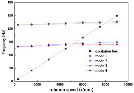
Reading the values of the intersection points, the first four-order critical speeds can be acquired and shown in Table 3 where BW is backward whirling and FW is forward whirling. The mode shapes corresponding to the critical speeds are shown in Fig. 6. As we can see, the vibration of the screw is much more serious than the bowl in the first and the second mode shapes. The weak point of the machine is the screw which needs for accurate dynamic balance. About the third and the fourth modes, the vibrations of the bowl become to be obvious and the phase difference between the bowl and screw is about 180 degrees.
Fig. 6Vibration modes of the decanter centrifuge

a) Modes 1 and 2

b) Modes 3 and 4
3.2. The influence of the differential mechanism
3.2.1. Numerical calculation
Due to the complexity of the internal gear and supporting bearing structure of the differential mechanism, the previous studies have never considered its influence on the whole machine. And as the middle part of the dual rotors, the differential should be studied and analyzed. In order to get the bearing stiffness, nonlinear static analysis is first performed and the results is shown in Table 4 where the numbers of the differential bearing are expressed as bearing symbol. Setting the model parameters such as bearing stiffness and solver type identical to the modal analysis without differential mechanism, the first six orders critical speeds are calculated and shown in Table 5, and the mode shapes corresponding to the critical speeds are shown in Fig. 7. As can be seen from the figure, differential mechanism vibration is the main feature of the first and the second modes, the third and the fourth modes are the vibrations dominated by screw, while the vibration phases of the bowl and the screw are opposite in the fifth and the sixth modes.
Table 4Critical speeds of the decanter centrifuge considering differential mechanism
Bearing number | 1 | 2 | 3 | 4 | 6309 | 6028 | 6307 | 6030 | 6311 | 6228 |
Stiffness (N/m) | 5.1×10⁹ | 4.1×10⁸ | 1.4×10⁹ | 1.3×10⁹ | 3.2×10⁷ | 4.7×10⁷ | 1.3×10⁷ | 8.1×10⁷ | 3.9×10⁷ | 1.1×10⁸ |
Table 5Critical speeds of the decanter centrifuge considering differential mechanism
Modes | 1 (BW) | 2 (FW) | 3 (BW) | 4 (FW) | 5 (BW) | 6 (FW) |
Critical speed (rpm) | 3243 | 3678 | 5555 | 5860 | 8380 | 8656 |
Fig. 7Vibration modes of the decanter centrifuge considering differential mechanism

a) Modes 1 and 2

b) Modes 3 and 4

c) Modes 5 and 6
Due to the cantilever of the differential, the critical speed caused by the differential flexural vibration is lower than the screw or bowl dominated critical speed. The machine is usually operated under the first order critical speed, therefore, when designing the differential, the length of the cantilever and the weight of the differential should be as low as possible in order to increase the critical speed. And when processed and assembled, the unbalance of the differential should be controlled precisely.
Comparing Fig. 6 with Fig. 7, the last four modes with the consideration of the differential are corresponding to the first four modes without differential. When the differential is taken into account, the four orders critical speeds increase by 10.9 %, 13.5 %, 4.4 % and 6.2 %. As we can find that the differential makes the vibration characteristics of the bowl and screw better as the result of restraint.
3.2.2. Experimental verification
As the model with differential is the most representative, this part of simulation is verified by experiment and the decanter centrifuge on site is shown in Fig. 8. During the experiment, the photoelectric sensor and the acceleration sensor are used to measure the rotation speed and the acceleration respectively. The voltage signal acquired by the sensors are processed and analyzed by DH5922 which is a kind of data acquisition and analysis system. With the system, vibration acceleration can be integrated so as to get the vibration velocity.
Through the experiment, variation of the vibration velocity with rotation speed is obtained as in Fig. 9. There are two kinds of state in the figure, one is the machine using the same differential mechanism (refer to “Type A” in Fig. 9) as that of the simulation, and the other is the machine with a shorter cantilever differential mechanism (refer to “Type B” in Fig. 9).
Fig. 8Field test
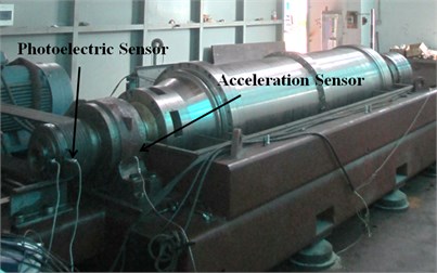
Fig. 9Variation of the vibration intensity with rotation speed
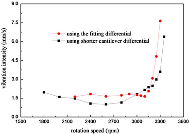
Because the velocity intensity exceeds 7.5 mm/s in the experiment which is considered as dangerous, the two tests didn’t pass the first order critical speed. As we can see from Fig. 9, the first order critical speed is about 3300 rpm while the machine is assembled with the fitting differential. The critical speed increases about 100 rpm when using a shorter cantilever differential, so we can see that the first order critical speed in the experiment is the bending vibration dominated by the differential which is identical to the simulation conclusion. Comparing the simulation result of 3678 rpm (forward whirling) with that of the experiment, the error between the simulation and the test is about 10.3 %. As the elastic supporting effect of the bearing block and the base is ignored in simulation, the simulation result can be considered as relatively accurate. The simplification of the structure, the 3D model and the iterative bearing stiffness method are proved to be reasonable and feasible.
3.3. The vibration of the bowl or the screw
With the bowl supported on the main bearings and the screw supported on the intermediate bearings, the critical speed of single rotor is calculated respectively without considering the differential mechanism. As the result shown in Table 6, compared with the first two orders critical speeds of the whole machine without differential, the critical speeds of the dual rotors system are lower than those of the single rotor. The screw plays the role of additional mass for the bowl of the whole machine. For the screw of the whole machine supported on the main bearings through the bowl and the intermediate bearings, the supporting stiffness is reduced compared with that of the single rotor supported on the main bearings. In general, the critical speeds of the dual-rotors system coupled by the two single-rotor through the intermediate bearings are lower than those of the single rotor system.
Table 6Critical speeds of screw or the bowl
Mode | Mode 1 (single bowl) | Mode 2 (single bowl) | Mode 1 (single screw) | Mode 2 (single screw) |
Critical speed (rpm) | 7256 (bw) | 7594 (fw) | 5929 (bw) | 6132 (fw) |
4. Unbalance response
4.1. Harmonic response
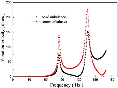
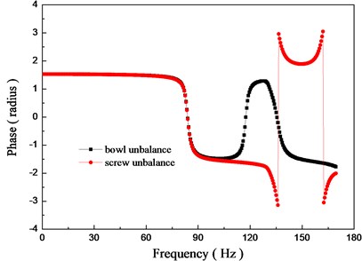
In order to determine the sensitivity of the whole machine to the bowl and screw unbalance, without considering the differential, harmonic response is adopted to calculate system amplitude and phase responses with the identical unbalance mass of the bowl and screw exerted at the same axial location respectively. The range of the calculated frequency is 0-170 Hz which is divided into 340 calculation points evenly while the rotation of the bowl and the screw is set to be synchronous. The solver type is set to be the full method. Gyroscopic moment and damping are considered while the material damping ratio is set to be 0.02 and the damping of the bearing is set as Eqs. (3)-(6). According to international standard of ISO 1940, balance quality grade is set to G6.3. Exerting the same amount of unbalance mass (0.018 kg·m), the results of the responses are shown in Fig. 10.
Fig. 10Unbalance response
a) Vibration velocity response
b) Phase response
As can be seen from Fig. 10(a), there are two vibration peaks of 84 Hz and 135.5 Hz in the frequency range from 0 Hz to 170 Hz which is identical to the modal analysis. Considering the mode shapes in Fig. 6, we can see that the unbalance of the bowl can cause vibration of the screw to a certain degree and the unbalance of the screw can also cause obvious vibration of the bowl, there is an interaction between the bowl and the screw. Comparing the system responses to the bowl and screw unbalance, there are both similarities and differences. In the frequency range studied, the trends of the unbalance responses to the different rotors are similar while the concrete values have big difference. The vibration of the system caused by the screw is much more obvious than that of the bowl, and the first two order peak amplitudes of screw unbalance are 1.86 times and 1.47 times that of the bowl unbalance.
As shown in Fig. 10(b), the changing tendency of the phase is the same when the frequency is lower than the first order resonant frequency while the phase responses become very different if the frequency is higher, which is identical to the conclusion of modal analysis that phase difference between the bowl and screw is about 180 degrees at the speed of second-rotor resonance. Even if for the synchronous rotation, the effects of different rotors on the system can have great difference and the dual-rotors system can never be simplified as a single rotor.
4.2. Transient analysis
When the decanter centrifuge is operated in engineering, there is slightly different rotating speed between the bowl and the screw. And the vibration characteristics of the system under the effects of bowl unbalance and screw unbalance is defined as the beat vibration which has rarely been studied before. As harmonic analysis can only be used to calculate the system response to a single rotor unbalance, transient analysis is conducted to analyze the system response to the double rotors unbalance so as to evaluate the coupling vibration characteristics of the system.
Without considering the differential mechanism, the solver type is direct method and the damping is set the same as harmonic response analysis. In the model, gyroscopic moment and geometrical non-linearity are considered. According to the engineering practice, the rotation speed of the bowl and screw are set to be 3280 rpm and 3200 rpm respectively. In order to improve convergence, two load steps are set. The time for the first load step is 10 and 70 for the second load step where is the rotation period of the screw. Every period of rotation is divided into 20 substeps in order to get the complete waveform of the vibration. For the sake of comparison, the amplitude of unbalance force caused by the bowl and the screw are all set to 2020 N, and the axial locations of the forces are the midpoint of the two main bearings. The transient unbalance forces of and direction are expressed by functions as shown in Table 7.
Table 7Expressions of unbalanced force
Unbalance force | The first load step | The second load step |
direction of the screw | ||
direction of the screw | ||
direction of the bowl | ||
direction of the bowl |
Fig. 11Waveform of beat vibration
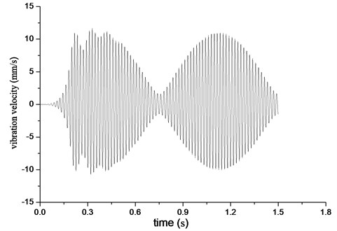
The result of system response under double rotors unbalance is shown in Fig. 11 where beat vibration is the main characteristics. Using the data of beat vibration in Fig. 11 and unbalance force in Table 7, applying the method introduced by Zhang Z. X. [13], the vibration of the bowl and the screw are calculated. The vibration value of the bowl is 4.69 mm/s ∠123° while the value of screw is 6.31 mm/s ∠123°.
Built on transient analysis, the system responses under a single rotor unbalance are also calculated respectively. The system vibration under bowl unbalance is 4.67 mm/s ∠125° and 6.31 mm/s ∠123° for screw unbalance, which is almost the same as the results under double rotor unbalance. It indicates that the unbalance of the bowl and the screw influence the system independently.
5. Conclusion
Using solid elements of ANSYS and applying iteration nonlinear bearing stiffness calculation method, coupled vibration characteristics of duals rotor system are simulated by modal, harmonic response and transient analysis. Certain conclusions are made as followed:
1) Taking no account of differential mechanism, the first and the second modes of the system are screw dominated bending vibrations while the third and the fourth modes are the vibrations that the phase difference between the bowl and screw is about 180 degrees. The critical speeds of the dual-rotors system are lower than any of the single rotor system.
2) Due to the cantilever of the differential, the critical speed caused by the differential flexural vibration is lower than that of the screw dominated or bowl dominated critical speed. Meanwhile, the differential makes the vibration characteristics of the bowl and screw better as the result of restraint.
3) The system responses differently for the different rotors under identical amount of unbalance mass at the same axial location. The amplitude is much more sensitive to the screw unbalance than the bowl unbalance, and the phase responses are also not the same.
4) The vibration characteristics of the system under the effects of bowl unbalance and screw unbalance is defined as beat vibration. The unbalance of the bowl and the screw exert independent effects on the system.
References
-
Hibner D. H. Dynamic response of viscous-damped multi-shaft jet engines. Journal of Aircraft, Vol. 12, Issue 4, 1975, p. 305-312.
-
Kazao Y., Gunter E. J. Dynamics of multi-spool gas turbines using the matrix transfer method – applications. International Journal of turbo and Jet Engines, Issue 6, 1989, p. 143-152.
-
Kazao Y., Gunter E. J. Dynamics of multi-spool gas turbines using the matrix transfer method – theory. International Journal of turbo and Jet Engines, Issue 6, 1989, p. 153-161.
-
Gunter E. J. Design of nonlinear squeeze-film damper for aircraft engines. Journal of Lubrication Technology, Vol. 99, Issue 1, 1977, p. 57-64.
-
Glasgow D. Nelson H. Stability analysis of rotor-bearing systems using component mode synthesis. Transactions of the ASME, Vol. 102, Issue 2, 1980, p. 352-359.
-
Guptak K. Unbalance response of a dual rotor system: theory and experiment. Journal of Vibration and Acoustics, Vol. 115, Issue 4, 1993, p. 427-435.
-
Sun G. Y., Palazzolo A., Provenza A., et al. Long duration blade loss simulations including thermal grows for dual-rotor gas turbine engine. Journal of Sound and Vibration, Vol. 316, Issue 2, 2008, p. 147-163.
-
Minh H. P., Philip B. An impulsive receptance technique for the time domin computation of the vibration of a whole aero-engine model with nonlinear bearings. Journal of Sound and Vibration, Vol. 318, Issue 3, 2008, p. 592-605.
-
Chiang H. W., Chih N. H. Roter-bearing analysis for turbomachinery single and dual Rotor systems. Journal of Propulsion and Power, Vol. 20, Issue 6, 2004, p. 1096-1104.
-
Chen G. Vibration modeling and analysis for dual-rotor aero-engine. Journal of Vibration Engineering, Vol. 24, Issue 6, 2011, p. 619-632.
-
Zeng S., Wang X. X. Unbalance identification and field balancing of dual rotors system with slightly different rotating speeds. Journal of Sound and Vibration, Vol. 220, Issue 2, 1990, p. 343-351.
-
Tan L. F., He S. Z. High-efficiency dynamic balancing method for dual-rotor system with slightly different rotating speeds. Journal of Vibration and Shock, Vol. 23, Issue 2, 2009, p. 31-33.
-
Zhang Z. X., Wang L. Z., Jin Z. L., et al. Non-whole beat correlation method for the identification of an unbalance response of a dual-rotor system with a slight rotating speed difference. Mechanical Systems and Signal Processing, Vol. 39, Issue 2, 2012, p. 452-460.
-
Li X. L., Zhang Z. X., He S. Z. Numerical analysis of a synchronous dual-rotor’s steady-state response. Journal of Vibration and Shock, Vol. 29, Issue 5, 2010, p. 162-165.
-
Liu Z. J. Rolling Bearing Application Manual. China Machine Press, Beijing, 2006.
-
Wu H. Research on the Dynamical Characteristics of Rolling Element Bearings and the Dynamic Model of Bearing Rotor System. East China University of Science and Technology, Shanghai, 2011.
-
ISO 6336-1. Calculation of Load Capacity of Spur and Helical Gears. 1996.
