Abstract
The paper presents application of the active synthesis method for determining parameters of identified bifurcated drive systems of machines together with parameters of active and passive reduction of vibration. The presented method uses the comparative synthesis method to determine the parameters of vibration reduction. The gist of the method is using dynamic properties, assumed at the beginning of the task, in the form of resonance frequencies and vibration amplitudes.
1. Introduction
Technological development, characterized by an increase in power and rotational speed of machines and devices drives, is inextricably linked with the growth in their dynamic activity. This may have a negative effect on stability, efficiency and reliability of machines and devices themselves, but may also adversely affect other mechanisms and living organisms in their close environment. Hence, the continuous development of research on reducing vibro-activity in the existing and designed machines and equipment. While there are many vibration reduction methods and techniques in already existing machines and equipment [1-10], the use of conventional design methods could not guarantee creation of designs with pre-established dynamic properties. At the same time, laborious and time-consuming classical methods evoked interest in network methods facilitating automatized calculations. They include graph methods, enabling easy algorithmization and automatization of calculations. Graph based network methods, developed in the Gliwice centre, have become a foundation for development of many tasks in modern technology [11-14], including methods of analysis and synthesis of vibrating systems [15-22].
The vibration reduction method presented in this paper can be classified as one of the design methods used in designing vibrating discrete systems as sub-components of machines with desired dynamic properties [7, 15-21, 23-25]. This work is a continuation of research on development of methods of synthesis of passive and active reduction of vibration in mechanical systems. Earlier work on active synthesis of mechanical systems focused on nominating a single control force reducing vibration amplitude of selected resonance frequencies [16-18, 20]. In case of passive synthesis, certain parameters of damping vibration components (dampers) were determined for one of the preselected vibration amplitude values [19, 21]. This study presents the use of active synthetic methods to determine parameters of setting forces, reducing vibrations of selected resonance frequencies. At the same time, it enables implementation of values of the forces in the system by means of passive elastic-damping components, as well as by combination of active and passive components in the system. Such extension of the synthesis task gives the designer a great number of options for selecting optimal parameters of the designed system.
2. Synthesis of unreduced drive systems of machines
Forming the dynamic properties of drive systems of machines [26-30] is a very important problem which should be included by a designer already at the stage of concept and initial design phases. Obtaining the system of required dynamic properties (frequencies of free vibrations) with the ability to control them is a complex problem ad it requires the use of graph methods which allow easy algorithmization and automatization of calculations. In the present work is presented the algorithm that expands earlier authors elaborations referred to the problem of forming dynamic properties of drive systems of machines using synthesis methods. The presented method of synthesis of machine drive systems, as discrete, twist vibrating models, allow determining parameters and the structure of a system for the assumed in advance resonance frequencies of a system and the required values of vibration amplitudes.
2.1. Dynamical properties of the system class under consideration
Prior to the task of active or passive vibration reduction with synthesis methods it should be determined the desired dynamic properties of the analysed system and the forces reducing vibration in an analytical form. The analytical form involves the determination of the slowness (mechanical impedance) characteristics in a form of rational functions that describe the analysed system of vibration reduction. The presented case occurs when forces reducing vibration dump the selected resonance frequencies of the dynamic characteristic to the required value of deflection, velocity or acceleration amplitude (in the paper is described only the case of deflection amplitude) of the analysed inertial component. In this case, the dynamic properties of the system are consistent with:
• , ,…, ( 1, 2, 3,…, ) – resonance frequency,
•, ,…, ( 1, 2, 3,…, ) – anti-resonance frequency (zeroes of mobility) chosen from the range ,
• , ,…, ( 1, 2, 3,…, ) – resonance frequency quenching coefficients defined in the form , where – the logarithmic decrement.
On the basis of the assumed dynamic properties, one determines the characteristic functions in the form of the slowness or mobility . In this work is considered the problem of the drive system that is characterised by the first frequency equal to zero (semi-determined system) in which the number of components is odd. Then between the number of resonance frequencies and anti-resonance one there is the condition , whereas the characteristic function takes the form of slowness of synthesized semi-determined systems:
where: – the constant of proportionality, – the Laplace operator.
The value of quenching coefficients of natural vibrations , ,…, are determined basing on the assumed desired values of amplitudes of vibration. The amplitudes are equal to the maximum deflection of the first inertial component, corresponding to the system response at the unit amplitude of the exciting force. In that case to determine the vibration quenching coefficients one should generate the graph of flexibility . Taking the values of amplitudes , ,…, , which correspond to the resonance areas , ,…, , are determined equations of surfaces , (1, 2, 3,…, . Any vibration quenching coefficient is the solution of next system of equations:
The number of solutions corresponds to the number of introduced resonance frequency quenching coefficients. By taking into account the resonance frequency quenching coefficient (desired vibration amplitude) and the required resonance and anti-resonance frequencies, it is possible to determine the analytic form of dynamical characteristics subjected to synthesis. The function defined in that way constitute the basis for using the synthesis methods in the active vibration reduction process.
2.2. Active synthesis of unreduced drive systems of machines
Prior to proceed to main identification, that means the determination of the active force on the basis of the assumed dynamic properties, one should determine the structure and parameters of the system subjected to the active vibration reduction. The structure of a drive system is determined by the used synthesis method [18, 20, 21]. In this work is presented the synthesis method of proportional parameters decomposition. In this method are used the characteristic decomposition into a continued fraction in combination with proportional parameters decomposition. The main advantage of the presented method is fact that desired properties of an analysed system are given only in a form of a resonance frequencies sequence , ,…, . For the synthesis of demi-determined systems resonance frequencies are presented in the next form:
where: , ,…, – resonance frequencies presented in the form of poles, , ,…, – resonance frequencies presented in the form of zeroes of mobility.
The slowness function of analysed mechanical systems, undergoing active vibration reduction, takes the following form:
As the result of the synthesis of the slowness function Eq. (4) by the characteristic decomposition of into a continued fraction (first using by Cauer (1958) [23]) it is obtained:
where: , ,…, – values of inertial components of the requested system, , ,…, – values of elastic components of the identified system.
The result of conducted synthesis, at this stage, is a lumped torsional mechanical system with multi-degree-of-freedom (MDOF) presented in Fig. 1. Dynamic characteristic, in the form of the slowness of the obtained system, is consistent with the slowness function subjected to the synthesis Eq. (4).
In the next step the control forces coefficients have been determined (other cases of the active synthesis are presented in [16-18, 20]). In order to achieve the desired vibration amplitudes of resonance frequencies of the analysed system (Fig. 1), the action of additional forces in the system is assumed (Fig. 2) in the form of:
where , , , – gain factors of the control system dependent on displacement and velocity of inertial components of the analysed system.
Fig. 1Torsional system obtained by decomposition of the slowness function Eq. (4)

Fig. 2Torsional system with active components of vibration reduction

On the basis of determined parameters of the identified structure of the system (Fig. 1) is created the stiffness matrix in the following form:
and using Eq. (6) the matrix of active forces:
Rows of the matrix Eq. (8) correspond to the values of active forces and to generalized coordinates of points which determine position of obtained inertial components to which the desired forces are applied. The proposed notation of forces location relates to a system on which act () active forces in relation to generalized coordinates of the obtained system as the result of conducted synthesis.
On the basis of the matrix and the stiffness matrix is determined the following polynomial:
In order to calculate the values of active forces the obtained polynomial should be divided by the factor , and then compare to the polynomial characterizing the assumed dynamical properties in the form of resonance frequencies and quenching coefficients of chosen free vibration. The equation takes the following form:
After comparison of coefficients at the same powers of polynomials of Eqs. (9), (10), one could determine parameters of active forces reducing vibration of the identified system. The presented method of active synthesis of vibration reduction is an universal one, which could be also used in different synthesis methods (e.g. characteristic decomposition into a continued fraction, hybrid method, etc.). In the next chapter is presented the utilization of obtained results for determining the bifurcated drive system.
3. Active synthesis of bifurcated drive systems of machines
In the chapter is presented the algorithm for determining parameters of a drive system with couplings – gear transmission (primary system) [20, 21]. For the synthesis of a multistage transmission are used the system obtained from Fig. 2, which is the model of a system reduced on the first axis of a shaft. The use of the inverse reduction approach, according to which kinetic and potential energy of a reduced system and of a primary system are equal, does not lead to uniqueness solution. For this purpose the additional condition is proposed, containing the statement that all sub-systems of a primary system should fulfil desired dynamic requirements in the form of chosen resonance frequencies. The synthesis of sub-systems of a primary system starts from disengagement the system into two sub-systems in relation to the first reduced component and from determining anti-resonance frequencies of the sub-systems disengaged with respect to the first reduced mass. For this purpose, basing on the stiffness matrix, are determined the algebraic cofactors in relation to the inertial component of the reduced drive system obtained as the result of a synthesis the form of:
Using Eq. (7) and Eq. (11) the slowness function is determined:
where: , .
Adopting from the slowness function Eq. (12), from the sequence of resonance and anti-resonance frequencies the highest values, one could form the dynamic characteristic that present properties of the desired, primary sub-system (reduced) on first axis. Such created function is subjected to the synthesis using the method of characteristic decomposition into continued fraction to determine parameters of the system before its reduction on its shaft with the stiffness in the form of:
where: , – values of inertial components, – value of the elastic component.
To ensure that the obtained dynamic parameters of a system will be accordant with the parameters of a reduced system it should be determined the proportional coefficient , which in a general case is equal to unity. The value of the proportional coefficient is determined to satisfy the next condition:
and function takes the form of:
where: , , . The determined values of components correspond to desired parameters of a drive system before reduction. For further synthesis is taken the sub-system of the desired drive system reduced on a shaft with stiffness , obtained by designing the structure and parameters of the separated sub-system of the primary system with stiffness (see Fig. 3).
Fig. 3Model of a drive system taking into account the first disengagement
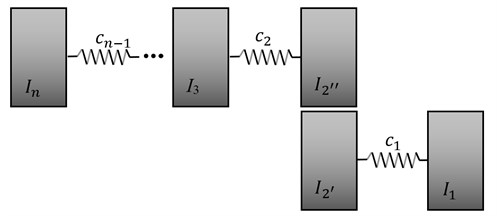
Parameters of the analysed sub-system take the next values:
The stiffness matrix of the analysed sub-system is:
and algebraic cofactor in relation to an inertial component of the stiffness matrix Eq. (17):
Using Eq. (17) and Eq. (18) the slowness function is determined:
Parameters of the desired primary sub-system on second axis, assuming that the sub-system fulfils the maximal resonance slowness’s Eq. (12) and anti-resonance slowness’s Eq. (19), are obtained as follows:
where: , – values of inertial components, – the value of elastic component. Basing on calculated values of parameters is determined the proportionality coefficient :
which enables to determine the sub-system parameters on a shaft with stiffness :
and parameters of the sub-system for the next analysis:
The process described with relations Eqs. (11)-(23) in continued till the moment of a system disengagement in relation to the inertial component . Values of stiffness’s of obtained sub-systems do not change in relation to the initial system, what in turn allows direct introducing previously determined forces to the created sub-systems without their modifications. To obtain the drive system with couplings it is needed to assume unit transmission ratios on each stage of the gear transmission expressed by the formula:
where: – total gear ratio, – gear ratio of subsequent stages of a gear transmission. Finally is obtained the following drive system, presented in Fig. 4.
Fig. 4Model of a drive system taking into account all couplings
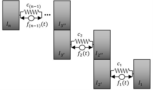
In the next step of synthesis for the obtained system is determined are determined parameters of the bifurcated system. For this purpose is used the method of proportional decomposition, taking the proportional decomposition coefficient in the range (0, 1). Depending on the requested two-terminals symmetry, with respect to the inertial component , the vales are determined as follows:
• Requested two-terminals of inertial type:
• Requested two-terminals of elastic type:
While the values of active forces are determined in the form:
The result is the bifurcated drive system presented in Fig. 5, which resonance frequencies meet the required dynamic properties.
The defined values of active forces, due to their configurations in the system, could also be obtained through both passive, elastic- damping components (Fig. 6) or by hybrid structure of active-passive components. Parameters of the passive system are determined in the form:
Achieving of real values of obtained dynamic parameters of the system is associated with their multiplication with chosen real transmission ratios on particular stages of each system bifurcation. Assuming then the transmission ratio on the first bifurcation in the form of:
are determine real dynamic parameters in the form of:
and values of active forces:
Fig. 5Bifurcated drive system with active components of vibration reduction
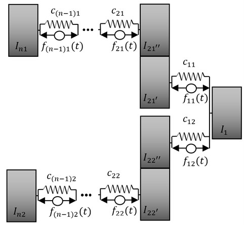
Similarly are determined real values of dynamic parameters and forces occurring in the second bifurcation of the drive system and in the case of analysis the system with passive components of vibration reduction (Fig. 6).
Fig. 6Bifurcated drive system with passive components of vibration reduction
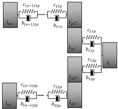
The presented synthesis algorithms allow the designer to very quick estimate the parameters and structure of a system, due to the required frequencies of free vibration. At the same time it must be emphasized that presented methods enable automating of calculations because of ease its algorithmization. Designated values of parameters of active forces and their location in the system are the quality solution of the presented method of active synthesis. Designing a system of active vibration reduction (Fig. 5), the parameters of control forces should be chosen in such a way to obtain the desired result of vibration reduction to the desired amplitudes values. The method of practical realization of determined forces, requiring the use of an automatic control system comprising a transducer of measured values, a controller and actuators (exciters), is beyond the scope of this paper. At the same time it should be stressed that determined parameters of active forces, could be also realized in the form of passive components (Fig. 6), what completely eliminates the use of additional control systems. Below is presented a numerical example of the described method.
4. Numerical example
In this chapter is presented a numerical example of determining parameters and a structure of a bifurcated drive system fulfilling dynamical properties, assumed in advance, in the form:
• resonance frequencies: 0 rad/s, 25 rad/s, 40 rad/s, 175 rad/s, 330 rad/s;
• amplitudes: 0.0004 rad, 0.0004 rad;
• real transmission ratios of the system: , .
In the first step of the synthesis is created a dynamic characteristic basing on the accepted resonance frequencies, in the form of poles and zeros, in accordance with Eq. (3):
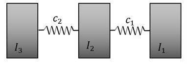
On the basis of Eq. (4) the resulting characteristic Eq. (32) is modified to the slowness function, and using Eq. (5) the parameters (see Table 1) and the structure of the system are determined (Fig. 7).
Table 1Value of elastic and inertial components
, kg/m2 | , Nm/rad | ||
1 | 3527 | ||
2.71 | |||
5.4 | 79250 | ||
Fig. 7Torsional system obtained by decomposition of the slowness function
The next step in identification of the system characteristic, after determining the parameters of the mechanical system, is modification the Eq. (32) by introducing the parameters of quenching in resonance frequencies of the system:
where , the values of resonance frequency quenching coefficients corresponds to the values , . Basing on the assumed vibration amplitudes, using the Eq. (2), the values of , have been determined. They are as follows: 5.16 rad/s, 2.75 rad/s. The graphical representation of the dynamic characteristic of the analyzed system, before and after modification, is shown in Fig. 8.
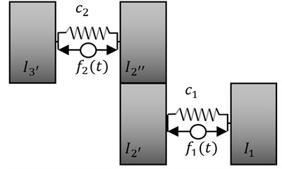
To obtain the determined vibration amplitude of resonance frequencies of the analyzed system (Fig. 8), it is assumed acting of additional forces in the system (Fig. 9), in accordance with Eq. (6).
Fig. 8Dynamic characteristic of the system subjected to synthesis
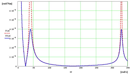
Fig. 9Torsional system with active components of vibration reduction

The values of control forces coefficients are determined using the relationships Eqs. (7)-(10). In the presented case they are as follows:
Next, using Eqs. (11)-(24), the structure of a drive system is determined (Fig. 10) together with the parameters set up in the Table 2. For such created structure of the system the values of parameters of active forces are consistent with these presented in Eq. (34).
Fig. 10Model of a drive system taking into account all couplings
After determining the parameters of the drive system (Fig. 10), it is possible to determine parameters and a structure of the bifurcated system. For this purpose, from the interval (0, 1) is adopted the coefficient of proportional parameters distribution 0.6, which is used to determine the values of requested two-terminals of the elastic type, of the inertial one and parameters of active forces in accordance with Eqs. (25)-(31). In the Table 3 are summarized the real dynamic parameters of the bifurcated dynamic drive system. It was taken into consideration the real parameters of active forces (Fig. 11(a)) and the passive parameters (Fig. 11(b)).
Table 2Value of elastic and inertial components
, kg/m2 | , Nm/rad | ||
1 | 3527 | ||
0.04 | |||
2.67 | 79250 | ||
5.4 | |||
Fig. 11Bifurcated drive systems
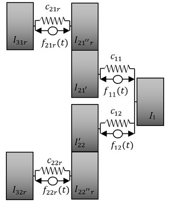
a) With active components of vibration reduction
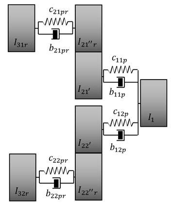
b) With passive components of vibration reduction
Table 3Real parameters of the bifurcated drive systems
, kg/m2 | , Nm/rad | , Nsm/rad | , Nm/rad | , Nsm/rad | |||||
1 | 47550 | 1.383 | 11.363 | 1.383 | |||||
0.024 | 235.11 | ||||||||
0.178 | 31700 | 1.524 | 3.878 | 1.524 | |||||
0.36 | 88.188 | ||||||||
0.016 | 47561.36 | 0.922 | 7.575 | 0.922 | |||||
0.067 | 238.988. | ||||||||
0.135 | 31707.58 | 0.571 | 1.454 | 0.571 | |||||
89.642 | |||||||||
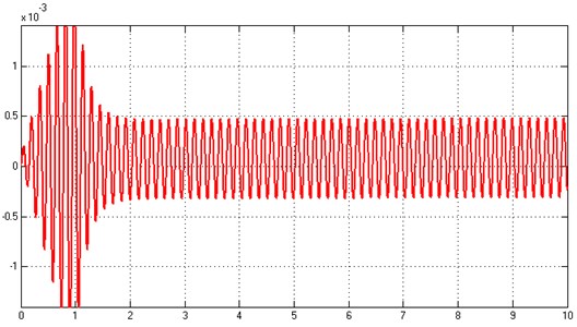
The determined parameters of active or passive vibration reduction allow to reduce vibration to the desired vibration amplitude of selected resonance frequencies. Using professional Matlab/Simulink software, calculations were performed to validate the results of passive and active vibration reduction of analysed systems (Fig. 11(a) and 11(b)) at the desired frequency spectrum. During the simulation, the periodic force with a unit amplitude and circular frequency corresponding to the fifth (Fig. 12) and third (Fig. 13) resonance frequency of free vibration of the system was assumed as the forcing signal. In addition, it was assumed that in the case of active vibration reduction, the control force is activated after 1 second.
The generated time characteristics of the reduced systems, with respect to the predetermined amplitude, confirm the correctness of the synthesis method in reducing vibration due to dynamic properties of a mechanical system.
+
Fig. 12Displacement of the first inertial component, taking into account passive reduction
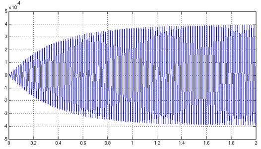
Fig. 13Displacement of the first inertial component, taking into account active reduction
5. Conclusions
The paper presents the use of active synthesis as the method of determining the parameters and structure of the designed mechanical system. Particular attention was paid to the task of vibration reducing to desired values of amplitudes. For this purpose the active synthesis approach was used, allowing the designation of a number of adjustment forces in the system. This is the extension of the traditional approach of the method of active synthesis of mechanical systems. Moreover, such assumption of adjustment forces allows to replace them with passive elastic-damping components, or to implement hybrid, passive-active structures. Such approach to the method of synthesis allows a designer of mechanical systems for higher flexibility in choosing both the type of a system structure, and the components which reduce vibration according to the assumed characteristic.
The basic practical implementation of synthesis methods relates primarily to the result of problem solving itself, that is the obtained set of mechanical systems with their parameters fulfilling in advance required dynamic properties. The developed methods of synthesis could be used not only during researching dynamical properties of requested objects but also in designing such systems as: drive, beam and mechatronic, due to the desired frequencies spectrum. Selection of parameters using the methods of passive and active synthesis of vibration reduction is one of the stages of real systems designing. The practical implementation relates also to the use of synthesis methods for identifying and assessing the parametric and structural sensitivity of mechanical vibrating systems. Determined adjusting forces could be the measure of structural sensitivity of systems with characteristics fulfilling the same dynamic properties. This approach is resulted from the diversity of forces obtained depending on the system subjected to active vibration reduction. It is possible to conclude that the smaller value of a control force, the greater structural sensitivity of a system on a change of the reduced resonance frequency. In addition, the set of values of active forces, fulfilling the same dynamic properties, could be used to optimize the forces controlling a system, due to the desired amplitude of vibration.
References
-
Liu Y., Hiroshi Matsuhisa H., Utsuno H. Semi-active vibration isolation system with variable stiffness and damping control. Journal of Sound and Vibration, Vol. 313, Issues 1-2, 2008, p. 16-28.
-
Kim S.-M., Wang S., Brennan M. J. Dynamic analysis and optimal design of a passive and an active piezo-electrical dynamic vibration absorber. Journal of Sound and Vibration, Vol. 330, Issue 4, 2011, p. 603-614.
-
Louroza M. A., Roitman N., Magluta C. Vibration reduction using passive absorption system with Coulomb damping. Mechanical Systems and Signal Processing, Vol. 19, Issue 3, 2005, p. 537-549.
-
Franchek M. A., Ryan M. W., Bernhard R. J. Adaptive passive vibration control. Journal of Sound and Vibration, Vol. 189, Issue 5, 1996, p. 565-585.
-
Alkhatib R., Golnaraghi M. F. Active structural vibration control: a review. The Shock and Vibration Digest, Vol. 35, Issue 5, 2003, p. 367-383.
-
Mottershead J. E., Ram Y. M. Inverse eigenvalue problems in vibration absorption: passive modification and active control. Mechanical Systems and Signal Processing, Vol. 20, Issue 1, 2006, p. 5-44.
-
Kolovsky M. Z. Nonlinear Dynamics of Active and Passive Systems of Vibration Protection. Springer, 1999.
-
Marcinkevičius A. H. Theoretical analysis of vibrations of a mass connected with a support trough a chain of elastic elements. Solid State Phenomena. Vol. 164, 2010, p. 303-307.
-
Guida D.,Pappalardo C. M. A new control algorithm for active suspension systems featuring hysteresis. FME Transactions, Vol. 41, 2013, p. 285-290.
-
Płaczek M. Dynamic characteristics of a piezoelectric transducer with structural damping. Solid State Phenomena, Vol. 198, 2013, p. 633-638.
-
Grabowik C., Janik W. The concrete casting matrixes inserts design preparation based on the master models. Advanced Materials Research, Vol. 702, 2013, p. 259-262.
-
Gwiazda A. Construction development using virtual analysis on the example of a roof support. Applied Mechanics and Materials, Vol. 474, 2014, p. 417-422.
-
Hetmańczyk M. P. The multilevel prognosis system based on matrices and digraphs methods. Solid State Phenomena, Vol. 199, 2013, p. 79-84.
-
Kalinowski K., Grabowik C., Kempa W., Paprocka I. The graph representation of multivariant and complex processes for production scheduling. Advanced Materials Research, Vol. 837, 2014, p. 422-427.
-
Dzitkowski T. Computer-aided synthesis of discrete – continuous subsystems of machines with the assumed frequency spectrum represented by graphs. Journal of Materials Processing Technology. Vols. 157-158, 2004, p. 144-149.
-
Dymarek A., Dzitkowski T. Reduction vibration of mechanical systems. Applied Mechanics and Materials, Vol. 307, 2013, p. 257-260.
-
Dzitkowski T., Dymarek A. Active synthesis of discrete systems as a tool for stabilisation vibration. Applied Mechanics and Materials, Vol. 307, 2013, p. 295-298.
-
Dzitkowski T., Dymarek A. Active synthesis of machine drive systems. Applied Mechanics and Materials. Vol. 430, 2013, p. 178-183.
-
Dymarek A., Dzitkowski T. The computer aided passive reduction of vibration to desired vibration amplitude. Applied Mechanics and Materials. Vol. 430, 2013, p. 342-350.
-
Dzitkowski T., Dymarek A. Active reduction of identified machine drive system vibrations in the form of multi-stage gear units. Mechanika, Vol. 20, Issue 2, 2014, p. 183-189.
-
Dzitkowski T., Dymarek A. Passive reduction in the identified vibrations of the machine drive system in the form of multistage gear units. Solid State Phenomena. Vols. 220-221, 2015, p. 182-187.
-
Sękala A., Świder J. Hybrid graphs in modelling and analysis of discrete-continuous mechanical systems. Journal of Materials Processing Technology. Vol. 164-165, 2005, p. 1436 - 1443.
-
Redfield R. C., Krishnan S. Dynamic system synthesis with a bond graph approach. Part I: synthesis of one-port impedances. ASME Journal of Dynamic Systems, Measurement and Control, Vol. 115, Issue 3, 1993, p. 357-363.
-
Park J. S., Kim J. S. Dynamic system synthesis in term of bond graph prototypes. KSME International Journal, Vol. 12, Issue 3, 1998, p. 429-440.
-
Smith M. C. Synthesis of mechanical networks: the inerter. IEEE Transactions on Automatic Control, Vol. 47, Issue 10, 2002, p. 1648-1662.
-
Świtoński E., Mężyk A. Selection of optimum dynamic features for mechatronic drive systems. Automation and Constructions, Vol. 17, Issue 3, 2008, p. 251-256.
-
Rao J. S. History of Rotating Machinery Dynamics. Springer Publication, 2011, p. 358.
-
Wu J. S., Chen D. W. Torsional vibration analysis of gear-branched systems by finite element method. Journal of Sound and Vibration, Vol. 240, Issue 1, 2001, p. 159-182.
-
Rao Z., Zhou C. Y., Deng Z. H., Fu M. Y. Nonlinear torsional instabilities in two-stage gear systems with flexible shafts. International Journal of Mechanical Sciences, Vol. 82, 2014, p. 60-66.
-
Byrtus M., Zeman V. On modeling and vibration of gear drives influenced by nonlinear couplings. Mechanism and Machine Theory, Vol. 46, Issue 3, 2011, p. 375-397.
