Abstract
This article details our research in the use of monocular cameras mounted on moving vehicles such as quadcopter or similar unmanned aerial vehicles (UAV). These cameras are subjected to vibration due to the constant movement experienced by these vehicles and consequently the captured images are often distorted. Our approach uses the Hough transform for line detection but this can be hampered when the surface of the objects to be captured has a high reflection factor. Our approach combines two key algorithms to detect and reduce both glare and vibration induced during image acquisition from a moving object.
1. Introduction
There is a growing interest in using unmanned aerial controlled vehicles for video capture, and traffic or crowd surveillance. However, the pre-existing technologies used in aerial surveillance activities are not yet mature, as they are not still adequate to deal with some of the challenges of capturing good quality video while attached these moving objects. Normally, video is recorded from one or more cameras attached to a usually lightweight flying drone, with a quadcopter being a popular choice in non-military applications; given its inexpensive yet relatively stable flying capabilities. Despite its stability, these flying objects are easily shaken by wind or oftentimes the rotation of its rotors. In an earlier study, the use of environmental features, such as line edges from buildings and street markings to reduce angular vibration induced in images taken from flying objects was explored [1]. However, that study is limited and additional techniques are still required to reduce translational vibration and reduce loss of important features in the scene which glaring surfaces or source can induce, such as driveway mirrors and direct sunlight. The focus of this research is to find ways to reduce the glaring effects of surfaces and stabilize the drone’s flight so that we are able to take improved quality videos.
Applying a multiple-camera setup can be used to find the depth of objects in a scene [4], and this could be used to find the drone’s position. However, the approach may need to set up multiple cameras on the miniature drone and it does not address the issue of glare. It would also increase the payload and introduce maneuverability issues, thus further affecting the stability of the drones and decreasing the quality of videos that can be taken. In [9], a high resolution camera was used to identify in-plane displacement on a microscopic scale in a vibrating steel plate using time average stochastic moiré. Other research, have explored vision-based measurement of static and dynamic vibration in large infrastructures and evaluated the performance in regards to sensitivity, resolution, and harsh environmental conditions in comparison with the measurement by a laser interferometer as reference [10]. These studies all highlight the importance of exploiting various features within the image in order to identify the characteristics of the vibration.
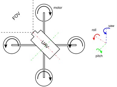
In this research, a complementary metal-oxide semiconductor (CMOS) camera is used because it is smaller, consume less power, and has a faster read-out speed compared to charge-coupled devices (CCD). CMOS cameras produce good images with higher signal to noise ratio, although they are still affected by vertical smear and rolling shutter effects if the camera moves during image acquisition. The following sections covers the methods used for feature detection and image registration, from which potential feedback information could be generated to control the four individual servos in the drone to adjust the roll, pitch and yaw (see Fig. 1) in order to damping out vibration during flight. Similar research in [11] on a twin rotor system, applied a fuzzy logic controller to improve pitch and yaw.
Fig. 1Quadcopter drone with four servo-motor for flight maneuverability
2. Feature detection and color space
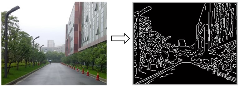
In our approach, we first use the lines within the captured scene to determine the vibration effects on the camera. This is achieved by running an edge detection algorithms on captured frames to highlight intensity boundaries and use these points that correlate to form a line for continuous tracking under high frequency vibration. In order to highlight these mentioned edges, the canny edge detection algorithm [2] is applied to produce a binary image in which pixels are marked as either edge or non-edge points (see Fig. 2).
Fig. 2Edges highlighted using the canny edge detection algorithm
In addition, our approach further uses a feature detection technique, the Hough transform, which is applied to select edges that form relatively straight lines. The Hough transform technique identifies lines by grouping point which form lines into a transformation matrix based on their parameters ρ (distance from origin) and θ (angle) as seen in Eq. (1):
where x0 and y0 are arbitrary coordinate points in the image where (ρ, θ) pair line passes through.
This line is then tracked in subsequent frames for rotational and transitional transformation which can be used in a feedback system to reduce the effect of vibration [3]. A major problem in using the method arises when line features in the image are undetectable as a result of glare caused by the reflection of sunlight into the image sensor. Combining a real-time glare reduction algorithm to the glared images should improve the detection but this may increase the amount of computation needed to process each frame. Other known solutions to glare reduction require that the scene only contain objects that are not in motion or the addition of cumbersome hardware to the image sensor, and are therefore not applicable for real-time tracking with the quadcopter [6-8].
The amount of luminance detected in the image, which is the brightness of an area/surface as a result of light reflection, is used to identify the amount of glare, see Eq. (2):
where Lv is luminance measured in candela/m2, θ is the angle between direction of view and the surface normal, Φv is luminous flux, A, the area in m2 of the surface, and Ω is the solid angle [5].
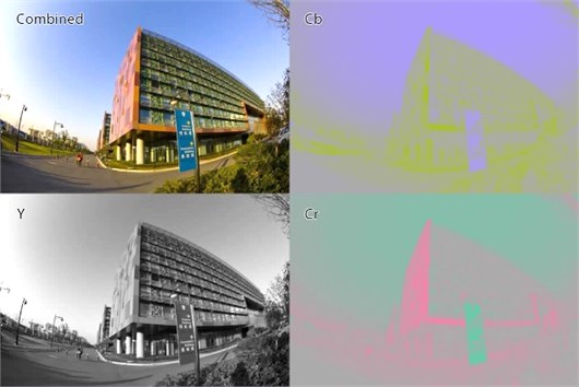
The luminance component of the image can be derived by converting the image to the YCbCr color space which is a mathematical representation of colors into three components where Y is the luma component (or luminance), Cb is the blue-difference, and Cr is the red-difference as seen in Fig. 3. The luminance component is extracted and the algorithm analyzes it to check the level of glare and then to enhance the image if necessary.
Fig. 3Image in real color with extracted Y, Cb, and Cr components
3. Implementation of algorithms
The monocular line tracking processes every subsequent frame using the algorithms provided below.
STEP 1: Acquire image and convert to the YCbCr color space (Fig. 3), and use the Y (luma) component to determine the average luminance threshold. Each pixel is then compared with the threshold to create a luminance mask which is used to determine if there is too much light reflection in the image (which causes glare).
STEP 2: If the amount of glare detected is lower than a predetermined percentage, nothing is done on the image and it skips to STEP 3; else only the Y component of the image is corrected by histogram shifting thereby retaining the color information of the image after the Y, Cb, Cr component are recombined.
STEP 3: At this stage the glare free image is then converted to grayscale and canny edge detection is applied to highlight the intensity boundaries (Fig. 1).
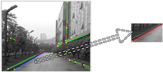
STEP 4: Compute the Hough transform and select the longest line (usually the most prominent line in the scene), see Fig. 4. A minimum length should be specified to prevent introducing new vibration from the feedback as a result of noise in the image.
Fig. 4Identification of most prominent line using Hough transform

STEP 5: Computation speed can be optimized by extracting only the area of the image that contains the line and searching that same region for changes in subsequent frames (Fig. 5). If there are no lines in subsequent frames, then another prominent line has to be re-determined from the entire image.
Fig. 5Computation speed optimized by processing only region of interest
STEP 6: The angular and translational difference in the line’s transformation can then be computed and used to correct the amount of vibration by moving the mounting body in the opposite direction with a calibrated de-vibration ratio to balance out the effect in the subsequent frame.
4. Simulation result and discussion
The results after subjecting the camera to vibration shows how the image is rotated in an opposite direction to simulate de-vibrating motion of the camera. The direction and amplitude of the vibration obtained in real-time can potentially be used in a feedback system to balance the motion of the quadcopter in flight by tracking lines in the scene. Thus exploiting the source of vibration by controlling the rotors to produce an inverse dampening motion [9]. In the top-right graph in Fig. 6 the red line with larger angular variations represents the angular vibration subjected by the camera, and the blue line indicates the relatively reduced vibration (see bottom-left for the transformed effect on image).
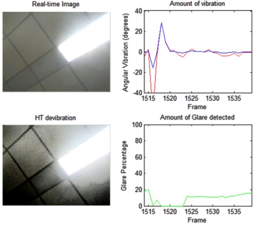
Furthermore the algorithm is able to detect glare in real-time and enhance line features in the image that is necessary for image registration – which is a process of correcting an image’s distortion by transforming it to match a base image. This can be seen in the bottom-left graph in Fig. 7, where the percentage of glare (i.e. green line in the bottom-right graph) is above the set threshold due to the light source within the field of view. The image in the bottom left corner clearly indicates the detected lines around the light source.
Due to the added computation required by combining the real-time glare and vibration reduction solutions into one, the images were acquired only at a maximum of 10 frames per second without any significant lag. The separate implementations enabled acquisition at 25 frames per second. The RANSAC algorithm (RANdom SAmple Consensus), another image registration technique was also tested. It calculates the image transformation induced during vibration by matching random data points in the based image and subsequent image. In comparison with the algorithm used in our research, the whole image is required in order to calculate the transformation angle and scaling. Moreover, when the random data points are not properly distributed to contain meaningful data for de-vibration, image jitter was observed. The RANSAC algorithm took 66.58 seconds to process 1000 frames compared to the Hough transform algorithm which took 63.79 seconds.
Fig. 6Some results from applying the Hough transform in image vibration reduction of monocular camera in motion
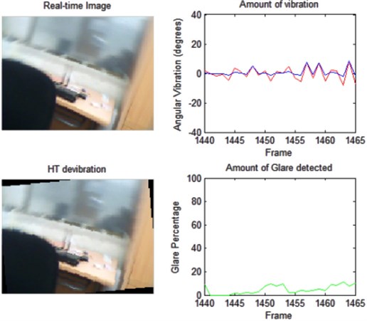
Fig. 7The reflection reduction algorithm results showing the original and enhanced frames
5. Conclusion and future work
This work is part of a bigger project in the exploration of real-time glare/reflection and vibration reduction algorithms that are applicable to unmanned aerial vehicles for traffic surveillance. This paper reports our latest approach to minimize the effects of surface glares and vibration of cameras placed on moving objects. The results of our technique show that it is effective, and it is based on (1) combining the two algorithms in an efficient way to reduce computation time; (2) establishing a foundation technique by which UAV can operate under weather conditions that reduce visibility; and (3) providing the necessary data for real-time balance flight for UAV every tenth of a second.
Further research is necessary to improve the accuracy of the measured distortions especially in images that have high levels of noise. Also, methods in which the frames processed per second can be increase would improve vibration reduction under more turbulent winds or faster flight speeds. Finally, the use of sensors such as the three-axis digital gyroscopes may be utilized when there is either very limited or no detectable line features in an environment. These sensors which are able to detect motion in various parts of the moving vehicle, can provide additional signals for vibrodiagnostics [12] thus enabling more accurate model of the systems for precise flight feedback.
References
-
Zhun Shen, David Olalekan Afolabi, Ka Lok Man, Hai-Ning Liang, Nan Zhang, Charles Fleming, Sheng-Uei Guan, Prudence W. H. Wong Wireless sensor networks for environments monitoring. Information Society and University Studies (IVUS), Kaunas, Lithuania, 2013.
-
Wikipedia. Canny edge detector, http://en.wikipedia.org/wiki/Canny_edge_detector.
-
David Afolabi, Zhun Shen, Tomas Krilavicius, Vladimir Hananov, Eugenia Litvinova, Svetlana Chumachenko, Ka Lok Man, Hai-Ning Liang, Nan Zhang Real-time vibration reduction in uav’s image sensors using efficient Hough transform. Proceedings of the 8th International Conference on Electrical and Control Technologies, Lithuania, 2013.
-
Saxena A., Schulte J., Ng A. Y. Depth Estimation Using Monocular and Stereo Cues. International Joint Conferences on Artificial Intelligence, 2007.
-
Wikipedia. Luminance, http://en.wikipedia.org/wiki/Luminance.
-
Bhagavathula K. Titus A. H., Mullin C. S. An extremely low-power CMOS glare sensor. Sensors Journal, Vol. 7, Issue 8, 2007, p. 1145-1151.
-
Nayar S. K., Branzoi V. Adaptive dynamic range imaging: optical control of pixel exposures over space and time. Ninth IEEE International Conference on Computer Vision, Vol. 2, 2003, p. 1168-1175.
-
Rouf M., Mantiuk R., Heidrich W., Trentacoste M., Lau C. Glare encoding of high dynamic range images. IEEE Conference on Computer Vision and Pattern Recognition, 2011, p. 289-296.
-
Ragulskis M., Maskeliunas R., Saunoriene L. Identification of in‐plane vibrations using time average stochastic moiré. Experimental Techniques, Vol. 29, Issue 6, p. 41-45.
-
Cigada A., Mazzoleni P., Zappa E. Vibration monitoring of multiple bridge points by means of a unique vision-based measuring system. Experimental Mechanics, Vol. 54, Issue 2, 2014, p. 255-271.
-
Taskin Y. Improving pitch and yaw motion control of twin rotor MIMO system. Journal of Vibroengineering, Vol. 16, Issue 4, 2014, p. 1650-1660.
-
Puchalski A. Application of statistical residuals in vibrodiagnostics of vehicles. Journal of Vibroengineering, Vol. 16, Issue 6, 2014, p. 3115-3121.
About this article
This project is partially supported by funds from the XJTLU SURF Fund (Code 201328), Research Development Fund (#RDF11-02-06) and ESFA (VP1-3.1-ŠMM-10-V-02-025).
