Abstract
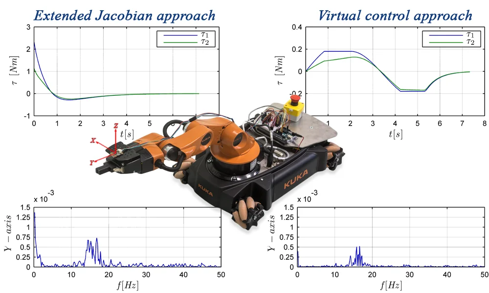
A new method of online trajectory planning for mobile manipulators using the extended Jacobian approach, taking into account state and control constraints, allowing the mobile manipulator to reduce the arm vibrations is presented. The proposed approach is based on the concept of virtual control which scales the trajectory preventing robot controls from changing rapidly and ensuring that the control constraints are fulfilled. The simulation results presenting the features of the developed algorithm have been shown. The effectiveness of the method in vibration reduction is confirmed by an experiment involving a KUKA youBot mobile robot.
Highlights
- Trajectory planning method with state and control constraints for nonholonomic wheeled manipulator.
- Extended Jacobian method using virtual control approach.
- Vibration reduction of the robot holonomic part during taks execution.
- The effectiveness of the method confirmed by an experiment involving a KUKA youBot mobile robot.
1. Introduction
The mobile manipulators can replace several stationary manipulators moving between multiple production workstations. In this application the main task is to plan the trajectory of the mobile robot in such a way as to place the robot end-effector in a specified location in the workspace. In practice, the most commonly used robotic system of this type is a holonomic arm mounted on a nonholonomic platform and therefore a, significant number of researches examine such mechanisms. The review study of mobile robots motion planning problems has been presented in [1]. Some of the works address the problem applying only kinematics, e.g. [2-5]. The use of such an approach does not guarantee to find a solution that can be implemented by a real robot. In the robotic systems the change of state is caused by the operation of the drive systems, so the dynamic properties of the robot should be taken into account. In the literature two approaches to the solution of the mobile manipulator task at the dynamic level are presented. In the first one, the arm and the mobile platform are considered as the separate subsystems. Such solution has been developed in the works [6-8]. In the second approach, the robot is treated as a single system governed by a single controller, e.g. [9-11].
In the works considering the trajectory planning problems the robot is usually treated as a multi-rigid body system and flexibility of the links and joints and looseness occurring in every real mechanical system are not taken into account. Such features may lead to vibrations that affect trajectory tracking accuracy and faster wear and tear of the mechanical parts. As shown in the author earlier work the form of the trajectory can reduce vibrations and increase positioning accuracy. Such results have been presented in [12], however it concerned trajectory planning at the kinematic level and did not consider dynamic properties of the robot. Problems resulting from the incomplete knowledge of the model are currently the subject of many studies, e.g. [13, 14], although they focus on robust control and do not consider vibrations. In this paper the method of trajectory planning taking into account dynamics and treating the mobile robot as a single system is presented. The key contribution of this study is the development of the new on-line controller with respect to both state and control constraints, which application leads to the reduction of vibrations occurring during the execution of the robot task. The proposed approach makes it possible to take into consideration a number of state limitations resulting from the properties and task of the robot and ensures that high manipulability of the arm is achieved at the final location. Moreover, by applying the trajectory scaling concept the control limitations, rarely taken into account in on-line control, are also fulfilled. The characteristics of the proposed controller is shown in simulations, and the effectiveness in vibration reduction is verified by the experiment using the KUKA youBot mobile robot.
2. Mobile manipulator task formulation
In the presented work a mobile manipulator composed of the nondegenerated nonholonomic platform [15] and the holonomic arm operating in -dimensional workspace is considered. The configurations of the platform and manipulator arm are described by -dimensional vector and -dimensional vector , so the configuration of the whole mobile manipulator can be described by -dimensional vector of generalized coordinates as follows:
One of the basic tasks that occur when using a mobile manipulator is to move the robot between individual workstations. It can be formulated as displacement the robot from a current configuration to the configuration ensuring the achievement of the specified end point in the workspace. In this case, it is assumed that in the initial moment of the motion the robot is in the fixed configuration . The task is to find the trajectory ensuring that in the final moment the end-effector is located at a specified point . Denoting by the mapping from to describing a kinematic equation of the mobile manipulator, the task can be expressed as:
Due to practical applications of the presented method it is assumed that the initial configuration is nonsingular, what allows the final location to be reached, and the mobile manipulator is stationary at the beginning and the end of the movement:
The movement of the mobile manipulator is subject to many limitations resulting from both mechanical properties and practical processes carried out by industrial robots. In the case of mobile manipulators composed of nonholonomic platforms, the motion of the robot is limited by phase constraints which can be represented in the Pfaffian form as follows:
where is Pfaffian full rank matrix and is the number of independent holonomic and nonholonomic constraints limiting the motion of the platform.
During the task execution the robot should fulfil mechanical constraints resulting from the allowed range of movements in its joints. Introducing the scalar function determining the algebraic distance between the current configuration and the limit of -th joint, these constraints can be expressed as a set of inequalities in the following form:
In the case of redundant robots, such as considered in this paper, the task described by Eq. (2) with constraints given by Eqs. (3-6) can be solved in different ways. The algorithm presented in this work allows for taking into account additional conditions to ensure high manipulability of the manipulator arm and fulfil control constraints of the whole robot. Moreover, the proposed approach reduces the undesirable vibrations of the manipulator caused by the platform movement.
3. Extended Jacobian approach
The presented solution is based on trajectory generation algorithms for single mobile manipulator [16, 17], which can also be extended to the case of cooperating robots [18]. The existence of the redundant degree of freedom of the robot makes it possible to achieve the solution taking additional criteria into consideration. For practical reasons, the robot trajectory should avoid singular configurations in which the arm mounted on the platform loses its manipulative capabilities. In order to come up with such a solution in the presented work minimization of some performance index leading to maximization of the distance between current and singular configurations is proposed. Using the manipulability measure introduced by Yoshikawa [19] this index can be described as follows:
where is analytic Jacobian of the manipulator arm and denotes the mapping from to describing kinematic equation of the manipulator arm.
In order to keep the configuration in the set of feasible solutions in the paper, approximate implementation of inequality conditions Eq. (6) by using the internal penalty function method has been used. According to this method, applying the internal penalty function increasing when the configuration approaches -th limit, the criterion Eq. (7) is extended as follows:
Finally, the optimal configuration which keeps high dexterity of the arm and satisfies mechanical constraints Eq. (6) should minimize the performance index Eq. (8) fulfilling task constraints Eq. (2) and phase constraints Eq. (5). As it has been shown in [17], the use of the necessary condition of index Eq. (8) leads to a set of constraints which can be written as:
where is a square matrix constructed from linear independent column of , is obtained by excluding from , , is dimensional vector obtained by choosing the elements from related to columns of matrix and in dimensional vector obtained by excluding from .
Eq. (9) is called a transversality condition. It introduces additional dependencies that complement the basic task of the mobile manipulator and lead to the solution which locally optimizes the performance index Eq. (8). Finally, the condition Eq. (9) combined with dependencies given by Eqs. (2, 5) defines the extended Jacobian of the mobile manipulator in the form of the full rank square matrix.
To solve the above task the feedback loop algorithm that corrects the robot movements based on feedback from sensors has been proposed. For this purpose, the error measure between the current and unknown, feasible configuration has been introduced as follows:
Denoting the first and second component of the vector as and the third component as , the system of homogenous differential equations with constant coefficients determining the trajectory of the mobile manipulator has been introduced:
where , , are, respectively, , and diagonal matrices with positive coefficients ensuring stability of the first and the second equation.
Using the Lyapunov stability theory it is possible to show that the solution of the system Eq. (11) is asymptotically stable for positive coefficients , and . This property of the system implies that when , then the mobile manipulator can achieve the final location with precision assumed for the task Eq. (2). Because the solution of the second equation in Eq. (11) is a constant function and it is equal to zero for , the phase constraints Eq. (5) are satisfied during the entire movement. Additionally, the task supplemented with transversality conditions is fully specified, then it can be shown that generalized velocities of the mobile manipulator tend to zero and constraint Eq. (4) is satisfied. Moreover, if the coefficients of matrices , fulfil conditions , the solution is a strictly monotonic function. For the nonsingular initial configuration satisfying mechanical constraints Eq. (6), this property forces to fulfil mechanical constraints as well as to carry out the motion of the mobile manipulator far away from singular configurations during the entire movement.
In order to determine the unique trajectory initial conditions should be given. They can be obtained by calculating the value of error measure Eq (10) for , taking into account conditions Eqs. (3, 5). Finally, the trajectory of the robot can be written in the compact form as:
where:
is dimensional square matrix, moreover minimization of the performance index Eq. (7) guarantees the movement away from singular configurations, so as it has been shown in [17] is also a full rank matrix.
The idea of the control system based on the generator Eq. (12) is shown in Fig. 1. As it can be seen, the problem is solved by a real-time trajectory generator working in the closed loop. The input signal of the trajectory generator () is the error vector (Eq. (10)) calculated based on the desired final location , a current location given by a kinematic equation (), holonomic and nonholonomic constraints of the platform (, Eq. (5)) and additional constraints () introduced by a transversality condition Eq. (9). Then the trajectory , , is used by a dynamic model (, introduced in Section 4) to determine a vector applied to control the robotic system.
Fig. 1The scheme of the proposed controller

4. Control constraints and vibration reduction
Every real robotic system is subject to some limitations resulting from the physical capabilities of the actuators used in its construction. The approach presented in this section allows for taking into account control constraints and simultaneously for reducing the vibration of the manipulator arm that results from control signals obtained from the generator based on Eq. (12).
The dynamic model of the mobile manipulator is given in a general form as:
where is dimensional positive definite inertia matrix, is -dimensional vector representing Coriolis, centrifugal, viscous, Coulomb friction and gravity forces, is -dimmensional vector of the Lagrange multiplayers corresponding to constraints given by Eq. (5), is full rank matrix by definition, describing which state variables of the mobile manipulator are directly driven by actuators and is dimensional vector of mobile manipulator controls (torques/forces).
In order to determine controls from Eq. (13), the vector of the Lagrange multiplayers should be eliminated. Taking into account that is dimensional full rank (by assumption) matrix, there exists a full rank dimensional matrix , orthogonal to , satisfying the condition . After multiplication Eq. (13) by the new form of the robot model is obtained:
and assuming the full rank matrix of control of the mobile manipulator can be determined as follows:
As it has been shown in the work [15], for any nondegenerate nonholonomic mobile platform it is possible to choose the configuration of the motorization which provides full platform mobility and ensures a full rank of the matrix , then it is possible to determine controls from Eq. (15) assuming the suitable motorization of the nonholonomic platform.
The implementation of the control algorithm in a real robotic system needs consideration of limitations resulting from physical abilities of the actuators. Such constraints can be written as a set of inequalities in the form of:
where are dimensional vectors denoting lower and upper limits on .
In order to fulfil constraints Eq. (16), the idea presented in the work [20] has been developed. In this paper the use of the virtual control scaling the trajectory Eq. (12) to satisfy control limitations in each time instant is proposed. The control is introduced in such a way as not to exceed the limitations resulting from the platform motion and the nature of the task being performed by the robot. The scaled trajectory can be written in the following form:
Substituting the Eq. (17) for Eq. (15) the controls of the mobile manipulator can be determined as a linear function of the virtual control :
where:
As it can be seen, if a control exceeds constraints Eq. (16), dependency Eq. (18) makes it possible to determine the virtual control , which scales the trajectory Eq. (17) in such a way as to satisfy control limitations. Due to the fact that there are some parameters difficult to include in the model, such as the looseness and flexibility (specific for individual mechanism) and parameters difficult to determine precisely, such as moments of inertia, a friction model and coefficients, etc., it is not feasible to determine the exact model of the robotic system. Determining the value of virtual control based on an imprecise model may lead to exceeding the control limits during the task execution by a real robot. For this reason, introducing the safety margins for and whose size is defined by scalar is proposed:
According to the proposed idea, the trajectory of the mobile manipulator is scaled when the controls exceed or , what keeps a certain margin allowing for making correction during the execution of the trajectory by control systems of the robot. When the controls of the mobile manipulator are within the range determined by Eq. (19), the virtual control is equal to 1. In this case, the trajectory is not scaled and the robot performs its task with respect to the original trajectory Eq. (12). Otherwise, if in the given time instant the -th control exceeds its limit, i.e. or , the value of should be determined in such a way as to satisfy the following inequality:
where and are the -th elements of vectors and , respectively.
If only one control exceeds the assumed limit, the virtual control scaling the trajectory Eq. (17) is selected as a boundary value fulfilling the inequality given by Eq. (20). In this case, the -th control is on the border of the safety zone Eq. (19). If several controls exceed their limits, it is necessary to determine the sets of feasible values for each control and choose an appropriate value from the intersection of these sets. The proposed approach does not ensure that the solution is found, even if it exists, due to the local nature of the presented method. Although, the only way to come up with a solution, is to use the global method, such an approach cannot be employed for real-time control. The presented algorithm is a compromise solution that allows control constraints to be taken into consideration and application for real-time control.
When, as a result of trajectory scaling, values of controls decrease and take the feasible values, the virtual control should be increased to its maximum value equal to 1. In order to ensure continuity of the controls , it is necessary to guarantee a continuous change of the virtual control . For this purpose, it is assumed that asymptotically increases according to the following dependency:
where is a positive coefficient determining the growth rate of the virtual control . In the experiment presented in Section 5 the coefficient is taken as dependent on the distance from the end point and it takes values between and as follows:
Fig. 2The scheme of the extended trajectory generator

Finally, substituting Eq. (21) and (22) for the scaled trajectory Eq. (17) the extended trajectory generator with respect to all assumed limitations including control constraints is obtained. The scheme of controller using the generator Eq. (17) is the same as the one shown in Fig. 1 except the block which should be replaced by the extended trajectory generator () presented in Fig. 2. As it can be seen, based on non-scaled trajectory , , calculated by the trajectory generator (Eq. (12)) the block determines the dynamic parameters and which allow for calculating the virtual control (Eq. (21)) in the block . At the end, the scaled trajectory Eq. (17) fulfilling control constraints is calculated in block .
It is worth noting that the proposed virtual control selection strategy leads to smooth changes of controls and results in smooth robot movements, which is an important advantage of the presented approach, significant from the practical point of view. Moreover, the coefficient makes it possible to influence the rate of increase of controls, both at the beginning and during the movement. Such a trajectory generation algorithm eliminates rapid control changes characteristic of Jacobian based methods that are disadvantageous for robot mechanical systems. What is more, in every real mechanical system there are some looseness and flexible elements, and therefore rapid control changes result in the vibration of the whole system, which is especially visible in mobile robots when rapid changes in the velocity of the mobile platform cause a manipulator arm vibration. As the experimental results show, the strategy proposed in this section significantly eliminates these undesirable effects.
5. Experimental setup and results
In order to validate the effectiveness of the approach presented above, the trajectory for the mobile manipulator consisting of the nonholonomic mobile platform and holonomic manipulator has been determined. Two cases have been considered: in the first one the virtual control remained constant, equal to 1, in the second case it has been changed according to the algorithm proposed in Section 4. To verify the efficiency of the method in reducing vibrations, the trajectories generated in this way have been executed by the mobile robot equipped with acceleration sensors to detect the manipulator arm vibration.
5.1. Mobile manipulator model
In order to plan the trajectory, the robot model composed of the nonholonomic platform of class and 4DOF 4R type holonomic manipulator, based on the KUKA youBot mobile manipulator has been used. The platform works in plane of the global frame. The local frame of the platform is attached at the top of the platform at the midpoint between two driving wheels, distant from each other by . The origin of this frame in a global frame is given by . The radius of the driving wheels is equal to , rotation angles around their axles are denoted as , and orientation of the platform is described by . The holonomic manipulator is connected to the platform at the point of frame and configuration angles of its joints are denoted as . In this case, the mobile manipulator is described by the vector of generalized coordinates:
During the task execution, the orientation of the end-effector is not taken into consideration, so the kinematic model of the robot is given as:
where:
The motion of the mobile platform is subject to one holonomic and two nonholonomic constraints, describing roll without lateral slipping [21], so constraints Eq. (5) take the form:
The parameters of dynamic model Eq. (13) have been determined using Newton-Euler approach. The approximation of the friction force composed of Coulomb and viscous friction components with coefficients and respectively, has been taken as:
5.2. Experimental setup
The effectiveness of the proposed approach has been tested using the KUKA youBot mobile manipulator. This robot is equipped with an omnidirectional platform with four Mecanum wheels, which can be applied to simulate the movements of any type of a platform. In order to obtain the nonholonomic motions typical to type platform, transformation between the velocities of the differential drive and youBot platform wheels has to be performed. According to the above subsection, denoting as the rotation matrix describing the orientation of the platform frame in the base frame, the kinematic model of the differential driven platform can be written as:
Denoting as , and , velocities of the left and the right wheels respectively and as and half of the length and width of the youBot platform, its kinematics can be described as:
Assuming and substituting the velocities of the differential driven platform for a kinematic model of the omnidirectional platform, after simple calculations the following dependency, describing the transformation between the velocities of the differential drive and youBot platform wheels, has been obtained:
As it can be seen, maintaining the equal velocities of wheels located on the same side of the platform leads to the youBot motion satisfying the holonomic and nonholonomic conditions presented in the Section 5.1.
Table 1Parameters of the mobile manipulator and the controller
Mobile manipulator | ||
Parameter | Platform | Manipulator |
Dimensions | , , , , , , | , , , |
Mass | , | , , , |
Friction | , | |
Controller | ||
Gain coefficients | , , , , | |
Control limits* | , | |
Safety margin* | ||
Growth rate* | , | |
* for the extended controller | ||
The KUKA youBot is equipped with 5DOF manipulator arm with revolute joints. The axis of the last joint is perpendicular to the axis of the previous one and the 5th configuration variable is responsible for the end-effector orientation. According to the adopted assumptions, the orientation of the end-effector is not taken into consideration, then the gripper and the last two links form the single link of the length equal to . Taking into account the above assumptions of the platform and arm, parameters of the robot determined based on the documentation [22] and parameters of the second controller used in the study are given in Table 1 (all physical values are expressed in the SI system).
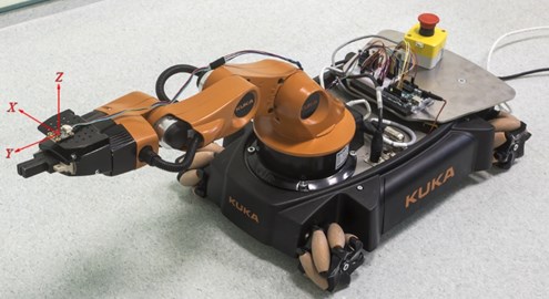
In order to study the influence of the proposed control strategy on the manipulator arm vibration caused by the platform movement, the three-axis linear LIS2DH accelerometer at the tip of the arm has been mounted as it can be seen in Fig. 4. The sensor, having adjustable sensitivity levels to ±2/4/8/16 g, is capable of measuring acceleration with output data rates from 1 Hz to 5.3 kHz and provides 16-bit data output. For the data processing purpose, the measuring subsystem based on the Arduino Uno board with ATmega328P microcontroller has been designed. At the beginning of the experiment LIS2DH has been initialized, then based on an error between the desired final location and the current state of the robot the control system has determined the control signal transmitted to the robot by EtherCAT. During the task execution the measuring subsystem has written the data from the accelerometer on SD card. After the task accomplishment, the stored data have been transmitted, using the HC-05 module, to the PC which controlled robot motion. The overview of the experimental setup has been shown in Fig. 3.
The task of the mobile manipulator has been to move the end-effector from the initial configuration to a certain point in the workspace. At the initial moment of the motion the robot has been in the nonsingular configuration in which the end-effector has been at the point . The task has been designed in such a way as to eliminate the need for arm movements and the robot has had to move to the final point . This way of formulating the task has allowed the impact of the used trajectory generator on the arm vibration amplitude to analyze by eliminating the influence of the additional factors such as work of arm actuators, that could interfere with the measurement results. The mobile robot with measuring system in the initial configuration has been presented in Fig. 4.
Fig. 3The overview of the experimental setup

Fig. 4The mobile manipulator and measurement system
5.3. Results and discussion
To present the effectiveness of the proposed algorithms two cases of performing the above task have been considered. In the first one the controller based on the trajectory generator Eq. (12) has been used and therefore control constraints have not been taken into account. In the second case the generator Eq. (17) with limitations on the wheels controls has been applied. During the task execution the manipulator arm has been stationary, so the limitations on the arm actuators have not been considered.
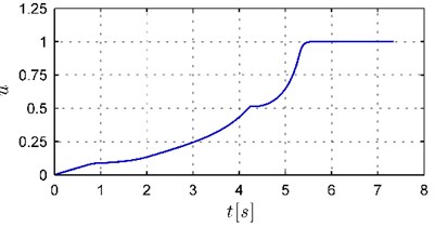
At first, in order to show the characteristics of control signals obtained by using both controllers, the simulations based on the robot model have been carried out. The robot motion in the workspace during the task execution in both cases has been similar as it has been presented in Fig. 6. The time execution has been below 8 seconds and it has been equal to 7.13 [s] and 7.34 [s], respectively. The wheels controls obtained in both simulations and virtual control determined in the second case have been presented in Figs. 5 and 7. As it can be seen the characteristics of controls are different for both controllers. In the case of the trajectory generator Eq. (12) the initial values of controls are large which leads to high acceleration of the mobile manipulator in the initial stage of the movement. When the extended generator Eq. (17) has been used, the changes of controls have been slower and the acceleration and deceleration phases have been clearly visible. Moreover, the virtual control determined according to the algorithm presented in Section 4 (see Fig. 7) has allowed for fulfilling the assumed limitations on wheels controls. Comparing the changes of values of controls to virtual control in Figs. 5(b) and 7 it can be seen that grows faster when controls are far away from a safety zone and slows down when are closer to this zone. Additionally, a small initial value of virtual control results in a slow increase of controls in the initial stage of the movement preventing the rapid velocity changes of the platform. Let us note that despite such significant limitations the use of the extended trajectory generator Eq. (17) allowed for the task to be completed in a similar time. As it will be shown below, the differences in the operation of the controllers, visible in the simulations, considerably influence the behavior of the real robot during the task execution.
Fig. 5The wheels controls of the platform
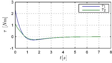
a) Trajectory generator Eq. (12)
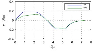
b) Trajectory generator Eq. (17)
Fig. 6The robot motion in the workspace
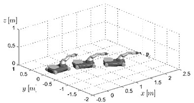
Fig. 7The virtual control u(t)
The main goal of the carried out research has been to verify by experiments how the used controller affects the vibrations of the arm of the real mobile manipulator performing its task. For this purpose, two experiments applying the KUKA youBot with measuring system described above have been performed. In both cases the robot has done the task considered in the above simulations. In the experiments both trajectory generators have been used: in the first one the generator Eq. (12) without the control constraints, in the second experiment the generator Eq. (17) with limitations on the wheels controls. The accelerations measured by a sensor in the , , and -axis in time domain have been shown in Fig. 8 and their frequency spectrum in Fig. 9. The rapid changes of accelerations, visible in the time domain, result from vibrations of the robot arm which are connected to the looseness and flexibility of the real mechanism. As it can be seen in Fig. 8(a) the use of the generator Eq. (12) leads to large arm vibrations in the first stage of the movement. Such results are the consequence of the features of the generator Eq. (12) which forces a quick change of the controls (see the characteristics of controls in Fig. 5(a). As shown by observations, the robot has achieved enormous velocities very fast and performed most of the task in the first phase of the movement (about 4 [s]). As discussed in the Section 4, the looseness and flexible elements in combination with rapid changes of the velocity cause manipulator arm vibrations. In the second phase, the vibrations have been small, because the robot motion has been very slow. As it can be seen in Fig. 8(b), in the experiment with the generator Eq. (17) the accelerations measured by sensors have spread evenly throughout the movement and their amplitudes have been smaller because the changes of velocities have been gentler and the motion has been steadier (see the characteristics of controls in Fig. 5(b)).
Fig. 8The acceleration in X, Y and Z-axis in time domain
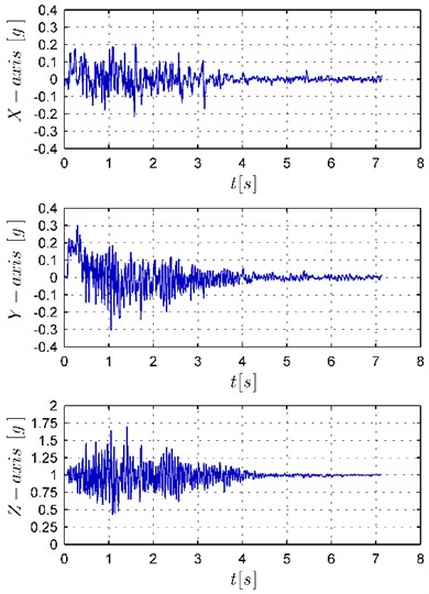
a) Trajectory generator Eq. (12)
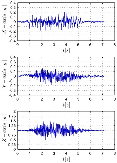
b) Trajectory generator Eq. (17)
The differences in vibrations of the robot arm are especially visible in Fig. 9 which presents the acceleration frequency spectrum. As it can be seen, the dominant vibrations are the vibrations in and -axis (note that the axis scales have been matched to the magnitude of the vibrations). The vibrations in the band from 10 to 20 Hz are visible both in the and -axis, additionally in the -axis there are also low frequency vibrations and in the -axis vibrations with frequency above 30 Hz. The performed analysis shows that the high frequency vibrations result from the features of the mobile manipulator used in this experiment. The omnidirectional platform of the KUKA youBot is equipped with Mecanum wheels causing the unavoidable vibration due to their structural shape [23] which can be interpreted as the motion on an uneven surface. As can be seen in Fig. 9(b), the use of the generator Eq. (17) results in a decrease in the vibration in the whole range of the frequencies in the , , and -axis. Additionally, the frequencies in the 10 to 20 Hz band are significantly damped in the and -axis as well as the low frequencies in -axis.
Fig. 9The acceleration frequency spectrum in X, Y and Z-axis
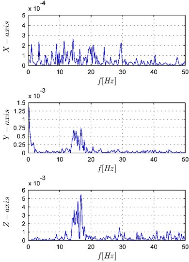
a) Trajectory generator Eq. (12)
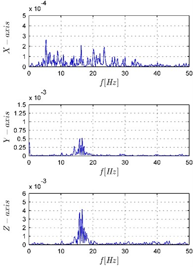
b) Trajectory generator Eq. (17)
6. Conclusions
In this paper a method of online trajectory planning for mobile a manipulator with respect to control limitations leading to reduction vibration of a holonomic part of the robot has been presented. As shown by the results of the performed experiments applying the methods based on the extended Jacobian matrix, which are effective in online trajectory planning, they usually result in trajectories that require large controls in the initial stage of the movement. These solutions are not desirable because actuators of the real robot may not be able to generate such torques. Moreover, the large initial controls values lead to rapid changes of the velocity of the robot and due to the looseness and flexible elements in real mechanisms may result in the vibration of the whole system. The approach proposed in this paper removes these shortcomings. Applying the concept of virtual control allows for the control constraints to be taken into account. Furthermore, it ensures the smooth control changes which, as shown by the results of the experiment, reduces the vibrations of the mechanical robot parts.
References
-
Tao B., Zhao X., Ding H. Mobile-robotic machining for large complex components: A review study. Science China-Technological Sciences, Vol. 62, 2019, p. 1388-1400.
-
Bayle B., Fourquet J.-Y., Renaud M. Manipulability of wheeled mobile manipulators: Application to motion generation. International Journal of Robotics Research, Vol. 22, Issues 7-8, 2003, p. 565-581.
-
Fruchard M., Morin P., Samson C. A framework for the control of nonholonomic mobile manipulators. International Journal of Robotics Research, Vol. 25, Issue 8, 2006, p. 745-780.
-
De Luca A., Oriolo G., Giordano P. R. Kinematic control of nonholonomic mobile manipulators in the presence of steering wheels. IEEE International Conference on Robotics and Automation, 2010, p. 1792-1798.
-
Tchon K., Ratajczak J. General lagrange-type jacobian inverse for nonholonomic robotic systems. ÍEEE Transactions on Robotics, Vol. 34, Issue 1, 2018, p. 256-263.
-
Mazur A. Trajectory tracking control in workspace-defined tasks for nonholonomic mobile manipulators. Robotica, Vol. 28, Issue 1, 2010, p. 57-68.
-
Zhong G., Kobayashi Y., Hoshino Y., Emaru T. System modeling and tracking control of mobile manipulator subjected to dynamic interaction and uncertainty. Nonlinear Dynamics, Vol. 73, 2013, p. 167-182.
-
Fareh R., Saad M. R., Saad M., Brahmi A., Bettayeb M. Trajectory tracking and stability analysis for mobile manipulators based on decentralized control. Robotica, Vol. 37, Issue 10, 2019, p. 1732-1749.
-
Huang Q., Tanie K., Sugano S. Coordinated motion planning for a mobile manipulator considering stability and manipulation. International Journal of Robotics Research, Vol. 19, Issue 8, 2000, p. 732-742.
-
Mohri A., Furuno S., Iwamura M., Yamamoto M. Sub-optimal trajectory planning of mobile manipulator. 2001 ICRA. IEEE International Conference on Robotics and Automation, Vol. 2, 2001, p. 1271-1276.
-
Tan J., Xi N., Wang Y. Integrated task planning and control for mobile manipulators. International Journal of Robotics Research, Vol. 22, Issue 5, 2003, p. 337-354.
-
Pajak I., Pajak G. Mobile manipulators collision-free trajectory planning with regard to end-effector vibrations elimination. Journal of Vibroengineering, Vol. 17, Issue 6, 2015, p. 2896-2906.
-
Dexu B., Wei S., Hongshan Y., Cong W., Hui Z. Adaptive robust control based on RBF neural networks for duct cleaning robot. International Journal of Control Automation and Systems, Vol. 13, Issue 2, 2015, p. 475-487.
-
Tsai C. C., Cheng M. B., Lin S. C. Robust tracking control for a wheeled mobile manipulator with dual arms using hybrid sliding-mode neural network. Asian Journal of Control, Vol. 9, Issue 4, 2007, p. 377-389.
-
Campion G., Bastin G., D’Andrea Novel B. Structural properties and classification of kinematic and dynamic models of wheeled mobile robots. IEEE Transactions on Robotics and Automation, Vol. 12, Issue 1, 1996, p. 47-62.
-
Pajak G., Pajak I. Planning of a point to point collision-free trajectory for mobile manipulators. 10th International Workshop on Robot Motion and Control, 2015, p. 142-147.
-
Pajak G., Pajak I. Sub-optimal trajectory planning for mobile manipulators. Robotica, Vol. 33, Issue 6, 2015, p. 1181-1200.
-
Pajak I. Real-time trajectory generation methods for cooperating mobile manipulators subject to state and control constraints. Journal of Intelligent and Robotic Systems, Vol. 93, 2019, p. 649-668.
-
Yoshikawa T. Manipulability of robotic mechanisms. International Journal of Robotics Research, Vol. 4, Issue 2, 1985, p. 3-9.
-
Pajak G. Trajectory planning for mobile manipulators subject to control constraints. 11th International Workshop on Robot Motion and Control, 2017, p. 117-122.
-
Siciliano B., Khatib O. Springer Handbook of Robotics. Second Edition, Springer Publishing Company, 2016.
-
KUKA Youbot Kinematics, Dynamics and 3d Model, http://www.youbot-store.com/developers/kuka-youbot-kinematics-dynamics-and-3d-model-81.
-
Bae J. J., Kang N. Design optimization of a mecanum wheel to reduce vertical vibrations by the consideration of equivalent stiffness. Shock and Vibration, Vol. 2016, 2016, p. 5892784.
