Abstract
Dent is a common defect of oil and gas pipelines and the assessment on dented pipelines is carried out according to major international standards and specifications with dent depth as the evaluation criteria. However, such evaluation criteria based on depth does not take the impact of other parameters (for instance, the internal pressure of pipeline) on the evaluation result into consideration; as a result, many dented pipelines that meet the specifications still lose their efficacy. In allusion to II-type plain dent existing on the oil and gas pipelines, the influence rule of the internal pressure of pipeline changes on the damage degree of dented pipelines is obtained on the basis of Oyane’s Ductile Fracture Criterion and by adopting the finite element numerical method.
1. Introduction
Dent is the most common form in oil and gas pipeline mechanical damage forms. Pipeline dent is a serious threat to the safe operation of the pipeline, especially under the action of internal pressure, residual strength and fatigue life of pipeline are decreasing, and the potential harm for pipeline safe operation are increasing.
At present, foreign countries conducted a series of studies for dented pipeline integrity assessment, for instance: Canadian pipeline design standards CSAZ662-03and its auxiliary manual CSA Z662.1-03, and other standards, all allow that the depth of dent can reach to 6 % of the pipeline diameter. But in fact, some pipeline, in the case of dent depth is lower than 3 % pipeline diameter, still leak. This shows that when the depth of dent meet the acceptability criterion, pipeline accidents will still happen. Therefore, the evaluation method simply based on the depth can’t meet the demands of oil and gas industry, so it need more parameters combined to evaluate the dented pipeline [1-6].
The author used the method based on damage mechanics to assess the damage degree of pipeline with type II plain dent. First, using finite element software ANSYS to establish the pipeline model, and obtained the results of different internal pressure. Second, using Oyane ductile fracture criterion based on damage mechanics process to dispose the results of finite element, then using damage variable represents the damage degree of pipeline. Finally, obtaining the influences of the internal pressure of pipeline changes on the damage degree of pipeline.
2. Oyane ductile fracture criterion based on damage mechanics
In the early 1980s, a Japanese scholar puts forward the Ductile Fracture Criterion based on ductile damage mechanics; moreover, this Criterion indicates its influence on the crack growth simulation. The expression of the ductile fracture criterion is as follows [7]:
In the formula, is integral value, which represents the cumulative damage of materials. is equivalent strain where the fracture occurs, is equivalent strain, is the equivalent stress, and are constants for materials.
– hydrostatic pressure:
– equivalent strain:
– equivalent stress:
In order to the get material’s integral value at a certain loading time before ductile fracture takes place, the constant can be divided from both sides of the equal sign of Eq. (1), then the value on the right of that equal sign will be 1; that is to say, when ductile fracture happens to the material, the integral value is equal to 1. Afterwards, when in Eq. (1) is substituted by the equivalent strain , it will become another equation as follows [8]:
If parameters () of the material at a certain time of the loading history have already been known, we can obtain its damage degree in combination with Eq. (2), and the integral value will be . In addition, the integral value on the right of the equation can not only stand for instantaneous faulted conditions quantificationally, but also show the material damage degree caused by stress-strain-history [9].
3. Finite element modeling
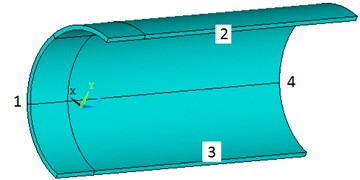
Finite element modeling steps are as follows: Because the pipeline model and loading conditions are symmetric, taking the one quarter of full pipeline as analysis model. Sections numbered 1, 2, 3 are imposed symmetry constraint, and section numbered 4 is fixed. Assumed that the constraint from ground to pipeline model is rigid and along the entire length of the pipeline, so the DOF of -direction on the bottom of pipeline model is constrained and the constraint range along the pipeline hoop is 120°. Fig. 1 is the schematic diagrams for the model of one quarter of the full pipeline.
Fig. 1The schematic diagram of the model of one quarter of the full pipeline
By assuming that type-II pure dent is formed by the press of ellipsoidal indenter item’s macro-axis parallel pipeline axis on the pipeline, under a circumstance of the same dent depth, the dent length will increase as the length of that trace application item’s long axis increases, and so does the dent width. The plain dent of type II diagram as following:
Fig. 2The schematic diagram of the plain dent of type II
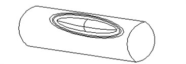
a)
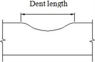
b)
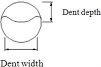
c)
Relative parameters of dent length and width are represented by adopting parameters and of different trace application items. When the dent depth are same, the length of dent increases with the increasing of and the width of dent increases with the increasing of . The value and (mm) respectively represents the minor and major axis length of ellipsoidal.
The finite element analysis steps are as follow: First, impose internal pressure; Second, impose dent on; Third, remove indenter.
4. The relationship between damage degree and dent depth on varied internal pressure
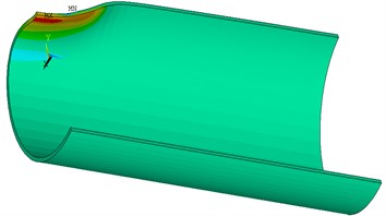
Assumed that the parameter of pipeline and the parameters of indenter are all unchanged, the damage degree expressed in integral value , then analysis the relationship between depth of dent and damage degree of pipeline under the varied internal pressure. Under the situation of is 0.02 ( 1000 mm) which is ratio of thickness and diameter, and the length of the pipeline model major axial is 2 which is equal to 3, the ratio ( 300 mm) of minor axe and major axe of ellipsoidal indenter is 0.3. The depth of dent (mm) respectively take 20, 40, 60, 80, 100, 120, 140, 160, 180, 200. The result of finite element calculation is as the Fig. 3 shows.
Fig. 3Unit integral value cloud picture of pipeline model
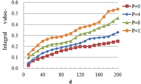
Under the condition of different pipeline internal pressure, the diagram of depth of dent and the integral value I is as the Fig. 4 shows.
From Fig. 4 it can be known that if the thickness of pipeline wall, the diameter of pipeline and the parameter of indenter are all unchanged, the integral value always increases with the increasing of depth of dent. Under the condition of varied internal pressure, the integral value increases with the increasing of the dent depth. Under the condition of same dent depth, the bigger the internal pressure, the larger the integral value . With the dent depth increasing, when 20 (mm), the integral value will significantly increase; however, if 20 90 (mm), will increase in a gradual manner. Apart from the curve which shows that internal pressure is equal to 0 (MPa), and when 90 (mm), the integral value increases to a larger extent.
Fig. 4The diagram of depth of dent and the integral value I with varied internal pressure
5. Conclusions
Summarizing the influences law of parameter on dent degree of dented pipeline, the final conclusion can be summarized as follows:
1) When the parameter of indenter is unchanged, the integral value always increases with the increasing of dent depth under the varied internal pressure. Under the condition of same dent depth, the bigger the internal pressure, the larger the integral value .
2) When the dent depth value is lesser, we can obtain the largest integral value from the inner side of pipeline wall, dent area 2; if the dent depth value is larger, the maximum value of can be obtained from the inner side of pipeline wall, dent area 1. To be specific, the area with the largest integral value is the area where the damage degree of pipeline is the severest. The division of dent area as shown in Fig. 4.
References
-
Ying Wu, Wu Liu, Huawen Wu, Peng Zhang Peak cycle stress analysis of plain dent on pipeline based on FE calculation. Journal of Vibroengineering, Vol. 16, 2014, p. 1268-1275.
-
CSAZ662-03, Oil and pipeline systems.
-
BS7910-2005, Guide to methods for assessing the acceptability of flaws in metallic structures.
-
AS2885.3-2001, Pipeline-gas and liquid petroleum.
-
API579-1-2007, Fitness for service.
-
ASME B31.4-2006, Liquid Transportation System for Hydrocarbons, Liquid Petroleum Gas, Anhydrous Ammonia and Alchohols.
-
Moriya Oyane Criteria for ductile fracture and their applications. Journal of Mechanical Working Technology, Vol. 4, 1980, p. 65-81.
-
Takuda H., Mori K. The application of some criteria for ductile fracture to the prediction of the forming limit of sheet metals. Journal of Materials Processing Technology, Vol. 95, 1999, p. 116-121.
-
Alloutia M., Schmitta C., Pluvinagea G., Gilgerta J., Haririb S. Study of the influence of dent depth on the critical pressure of pipeline. Journal of Engineering Failure Analysis, Vol. 21, 2012, p. 40-51.
About this article
This work is partially supported by the Grants from the National Natural Science Foundation of China (No. 50974105), the Applied Basic Research Project of Sichuan Province (No. 2013JY0098), the Education Department Research Project of Sichuan Province (No. 14ZB0057), and SWPU Science and Technology Fund: Project Name (No. 2013XJZ021).
