Abstract
With the engine room of certain training ship for navigation teaching being the prototype, the numerical model was developed for three cabins with floating cabin to predict the structure-borne noise (SBN) in ship cabins. The finite element model of multi-tanks structure was built when the vibro-acoustic coupling system was simplified. The predicted results for SBN were compared with the measurements done on a cabin mock-up. The effects of vibration isolator and constraint damping materialss were investigated. Comparisons of the predicted results and the experimental results showed that the developed model could be an effective tool for predicting SBN in ship cabins. The elastic mount installed positions on the auxiliary diesel engine are selected as the force excitation points. The finite element/boundary element method to predict sound pressure level (SPL) of the machinery control room and mechanical workshops of the ship, The sound pressure color nephogram of symmetrical field points on two sides is compared and analyzed, thus the degree of contribution of all bulkheads to the SPL in the right ear position of the duty engineer is acquired. And the floating cabins design based on floating floor is verified to effectively decrease the noise in cabin. The method and process of predicting vibration and sound of the vessel engine room are summarized, which could be a reference for reducing vibration and noise of ships.
1. Introduction
Noise pollution has become one of three major pollutions including air pollution and water pollution, which is increasingly raising concerns. Not only does ship noise account for the structural fatigue damage by acoustics-vibration, but also influences the normal operation of various instruments and equipment, ranging from the discomforting the environment to the serious damage to people’s health. The vessel engine room is the sources of vibration and noise in the working and living areas, which makes it a critical project to find an effective and practical approach of prediction analysis and control to address the noise problems in the ship cabins [1-4]. The code on noise levels on board ships of the International Maritime Organization (IMO) that will enter into force lower the standards of the noise in the ship cabins and other places by 5 db. To comply with the rules which have higher standards on engine control room, it is universally accepted to design floating cabins which are based on the floating floor to make the cabin in a “floating” status within which the air noise and machine vibration were separated perfectly to achieve fair vibration damping and noise proof function [5-7]. It is generally acknowledged that finite element method (FEM) and boundary element method (BEM) are more accurate and have more applications as far as acoustic radiation is concerned [8-13]. Based on the engine room of one training ship for navigation teaching, the study simplifies acoustic coupling system into the finite element model of multi-tanks structure with the vibration of auxiliary diesel engine an excitation source. It studies structural vibration and the features of the acoustic radiation in the floating cabins (Machinery control room) in the ship cabins that are covered with floating floor by using FEM/BEM. Furthermore, the study was carried out by applying the LMS test lab vibration noise analysis system to make comparison and verification.
2. The components of vessel engine room model
2.1. The components of ship floating cabin
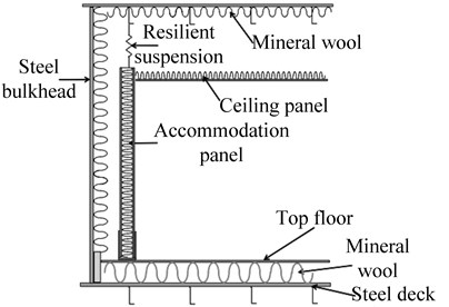
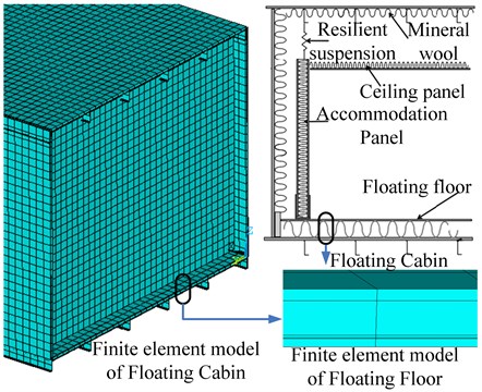
Ship floating cabin (e.g. Machinery control room) shall be arranged in the way, which is to initially nail the lining plates and independent enclosure of cabin to the floating floor and separate them from the steel deck, and join the independent enclosure of cabin and the ceiling with bulkhead by vibration isolating damp. The cabin is in a “floating” status within which the air noise and machine vibration were separated perfectly to achieve fair vibration damping and noise proof function. The floating cabins are based on the floating floors which are light and capable of reaching the fireproofing grade of A-60. The mineral wool between the floating floors has the effect of elastic floating, which not only meets the needs of fireproofing division in the cabins of the main deck which vibrates violently, but also ensures the comfort of the cabins. The structure of floating cabins is shown in the Fig. 1.
Fig. 1The schematic drawing of floating cabin
2.2. The components of three cabin models
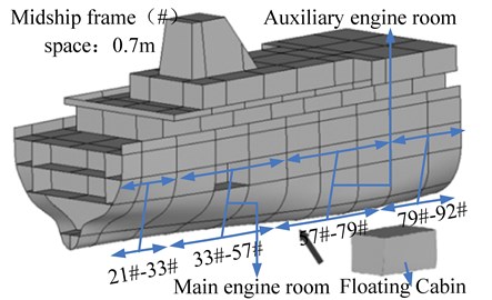
The basic parameters of the training ship are as follows: the length overall of the ship is 116 m, length between perpendiculars of the ship is 105 m, the breadth is 18 m, the bottom to main deck is 8.35 m, designed draft is 5.4 m. The main engine room section and auxiliary engine room section are selected, with the bow and stern expanding by half a cabin. Three cabin models are set up, mid-ship frame (#) spacing: 0.7 m, the end of the model: #21 the head of the mode: #92, the main engine room: #33-#57, the auxiliary engine room: #57-#79. The main engine and relevant system devices, machinery control room, mechanical workshops are located in the engine room, while three auxiliary generator diesel engines equipped with the vibration isolation are contained in the auxiliary engine room. The three cabin models and floating cabin are shown in the Fig. 2.
Fig. 2The schematic structure of three cabin models
3. Computation and measurement on vibro-acoustic characteristics of simplified model
3.1. Establishment of simplified model and actual physical model
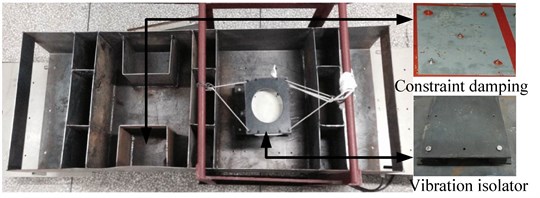
The engine room of one training ship for navigation teaching was taken as a prototype. The shape of actual cabin is not regular. Targeted engine room is simplified into the models of multi-tanks structure proportionately in order to illustrate qualitatively problems and consider the symmetry of the ship structure. The simplified model is as follows: considering the liquid tanks are generally close to both sides, which consists of bulkhead (BHD), the models set up six liquid tanks (LT), number from 1 to 6. When the liquid tanks are not used to fill tanks, they are considered to strengthen the structure in part. The models also set up five acoustic cabins (AC), numbers from 1 to 5, NO. 1 AC and NO. 2 AC are arranged symmetrically. Constraint damping materials are laid in top plate (TP) and floor board (FB) in NO. 1 AC, which is similar to the machinery control room. The sectional views of simplified models as shown in Fig. 3.and Fig. 4. The vibration source in this model test is merely a vibration exciter (as shown in Fig. 5) simulates auxiliary engine room alternator prime movers (auxiliary diesel engine), The experiment uses vibration exciter to sweep sine excitation. Excited position (EP): (1.0 m, 0.25 m). The vibration isolator (VI) is installed in the symmetrical position of the model’s EP. Physical model and test system are shown in Fig. 5.
Fig. 3The horizontal sectional views of simplified model
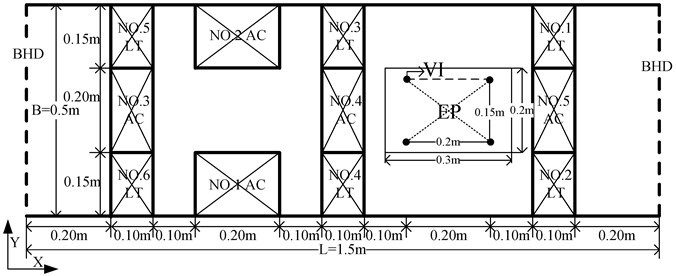
Fig. 4The cross sectional views of simplified model
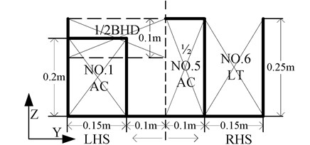
Fig. 5Actual physical models and LMS test system
3.2. Numerical calculation and experimental verification between structural vibration and acoustic radiation
Finite element model coordinate system uses Cartesian coordinate system. The X-axis is pointing longitudinally to the bow along the hull, while Y-axis is pointing molded breadth to the port along the ship. The Z-axis is pointing molded depth up along the hull; the both sides (H-side and S side) and central longitudinal section (CLS) of the model are required constraints. Boundary conditions of the model are shown in Table 1. While finite element model and boundary conditions are shown in Fig. 6. Material parameters and real constants: plate: ET, 1, SHELL181 & MP, EX, 1, 2E11 & MP, PRXY, 1,0.3 & MP, DENS, 1,7800 & SECTYPE, 1, SHELL & SECDATA, 0.004,1. The damping materials are rubber, the constraint layer is made of steel plates, select the ship’s top plate and floor board which make great contributions and constraining damping materials are applied, constrained damping structure: ET, 1, SHELL181 & MP, EX, 1,2E11 & MP, PRXY, 1,0.3 & MP, DENS, 1,7800 & MP, EX, 2,3.4E6 & MP, PRXY, 2,0.49 & MP, DENS, 2980 & SECTYPE, 2, SHELL & SECDATA, 0.004,1 & SECDATA, 0.002,2 & SECDATA, 0.002,1. The vibration isolator is installed in the symmetrical position of the model’s exited position, isolator: ET, 3, COMBIN 14 & R, 3,1.2E5, 25 & R, 4,2.45E5, 50 & R, 5,5E5, 42.The complete method is used to have the harmonic response analysis. The calculation interval of the frequency is set to 50 Hz-1000 Hz. The amplitude of excitation force 5 N. The result is used as the input of the boundary element model boundary condition. It also applies Virtual.Lab to make calculation of sound field.
Fig. 6Finite element model and boundary conditions
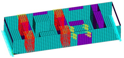
Fig. 7Sound pressure color nephogram of field point
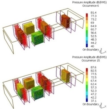
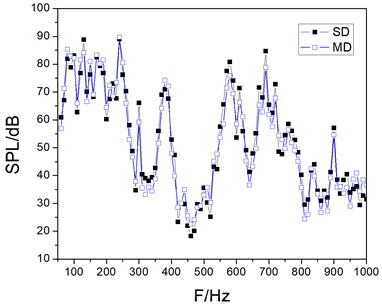
To verify the accuracy and validity of the developed model, the predicted results were compared with the corresponding experimental results, which comprised measurements done on a mock-up that simulates a typical ship cabin structure, as shown in Fig. 5. The experiment uses vibration exciter to sweep sine excitation. Excited position (EP): (1.0 m, 0.25 m). The sound signal employs piezoelectric acoustic sensor acquisition in the laboratory; LMS SCADAS and LMS Test.Lab are seamlessly integrated to ensure quality and accuracy of the data. Fig. 7 shows sound pressure color nephogram of field point in the sixth-mode and fifteen-mode. As the constrained damping materials are laid on the NO. 1 AC, the sound pressure level of the NO. 1 AC was significantly less than the NO. 2 AC. Fig. 8 indicates the comparison between simulation and measurement SPL data of field point1 (0.50 m, 0.075 m, 0.10 m). Due to local vibration happens in the sixth-mode and fifteen-mode of NO. 1 AC, the peak appears between 84 Hz and 128 Hz. The error of simulation data (SD) and measurement data (MD) results analysis is less than 5 % in Fig. 8, indicating that this method has better accuracy.
Table 1Boundary conditions of the model
Position | Linear displacement constraints | Angular displacement constraints | ||||
Direction | Longitudinal | Lateral | Vertical | Longitudinal axis | Lateral axis | Vertical axis |
H-side | fixed | – | fixed | – | fixed | fixed |
S-side | – | – | fixed | – | fixed | fixed |
CLS | – | fixed | – | – | – | – |
Fig. 8Comparison between simulation and measurement SPL data of field point 1
3.3. Analysis results of characteristics of structure-borne noise
3.3.1. Acoustic characteristics of cabins under the influence of vibration isolator
Finite element model of simplified model was established to observe acoustic effects caused by installing isolator. Fig. 9 and Fig. 10 indicate the sound pressure level curve of the central field point 1 in NO. 1 AC (0.5 m, 0.075 m, 0.1 m), the central field point 5 in NO. 5 AC (1.25 m, 0.25 m, 0.125 m) respectively.
Fig. 9The sound pressure level curve of field point 1
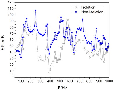
Fig. 10The sound pressure level curve of field point 5
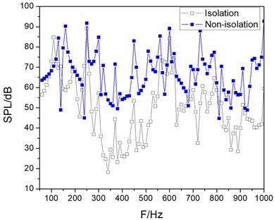
According to the modal theory and wave theory, when the frequency of disturbance force is much lower than the natural frequency of the cabin model structure or disturbance force to stimulate long-term model of bending wave length is greater than the model, the vibration of the model will mainly show whole vibration. Layout of the vibration isolator has a little impact on noises in various cabins. However, due to the complex structure of panels, horizontal panels, locally strengthen structure, bending waves in various structures have quite different wavelengths. With the distinction of excitation frequencies, vibration response is not the same in different cabins. Sound pressure level of the field point 1 and field point 5, as shown in Fig. 9 and Fig. 10. It can be seen the influence of installing isolators are roughly the same rules in different fields at low excitation frequency; when it reaches higher frequency, the difference of rules are relatively enormous. According to prediction results of the cabin noise, installing the vibration isolator where the excitation source location is can reduce noise levels in the cabin efficiently.
3.3.2. Acoustic characteristics of cabins under the influence of constraint damping materials
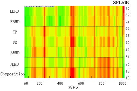
Panel color bars contribution display of NO. 1 AC is able to illustrate clearly the acoustic contribution in different panels, as is shown in the Fig. 11. Floor board (FB), top plate (TP), left bulkhead (LBHD) and right bulkhead (RBHD) makes great contributions. The researchers use constraint damping materials to restrain the vibration of the panels. The damping materials are rubber, the constraint layer is made of steel plates. Select the ship’s top plate (TP) and Floor board (FB) which make great contributions and constraining damping materials are applied.
Fig. 11Panel color bars contribution display of NO. 1 AC
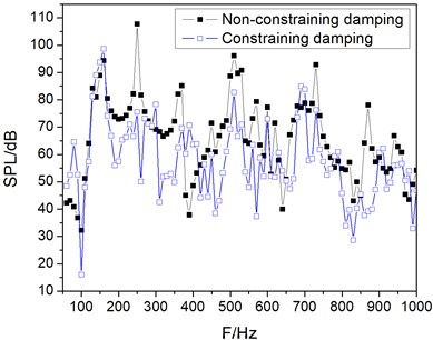
The sound pressure level of the central field point 1 in NO. 1 AC (0.5 m, 0.075 m, 0.1 m) constraining damping and non-constraining damping is shown as the Fig. 12. It can be seen that the noise in the cabin is obviously decreased especially between 200 Hz and 600 Hz. The researchers define various plates that make contributions to acoustic cabins. The plates which make great contributions to corresponding acoustic should be found out so that the noise problem can gain preliminary solution by constraining damping materials.
Fig. 12The sound pressure level curve of field point 1
3.4. Prediction and control on vibro-acoustic environment of vessel engine room simplified model
The comparison between simulation and measurement SPL data can be proved that the numerical simulation calculation has better accuracy, on this basis, indirect boundary element method is applied for further analysis. Set the excitation source location isolator significantly reduces the vibration energy transmission to the base of the hull structural. Through the analysis of acoustic contribution of cabin panels, using constrained damping material upon acoustic panels can reduce vibration and sound radiation and improve vibro-acoustic performance effectively. The study has instructive effect on the acoustic design and noise prediction of the ship and also provides an effective basis for noise and vibration control of the ship.
4. The establishment of numerical calculation model
4.1. The establishment of the finite element model of the floating cabin
According to the structural traits of the floating cabin, the cabin is divided into deck, bulkheads, beam, frame and stringer. Every part is modeled separately to become the sub model of the cabin, and they are intetrated into the complete cabin model, as is shown in Fig. 13. Take the floating floor for instance; the ANSYS program is applied to analyzing the laminated composite shell of floating floor. Proper material features and shell181 were used for intellectual meshing. Steel plate elastic modulus: 2.10E11 Pa, Poisson’s ratio: 0.3, density: 7800 kg/m3; special rubber elastic modulus: 6.50E8, Poisson’s ratio: 0.49, density: 1000 kg/m3; mineral wool elastic modulus: 6.20E6, Poisson’s ratio: 0.226, density: 100 kg/m3; composite materials elastic modulus: 8.00E9, Poisson’s ratio: 0.16, density: 1710 kg/m3. The materials of the floating floor consist of 2.0 mm special rubber and 2.0 mm galvanized steel sheet from the bottom up respectively, which provides a quality acoustic performance within the lowest height. In addition, it also concludes 40 mm mineral wool and 20 mm composite materials, which effectively lowers the noise that is caused by the impact damage and structural vibration.
Fig. 13The schematic drawing and finite element model of floating cabins
4.2. The establishment of the finite element model of the engine room
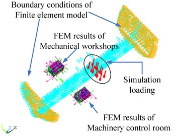
For the sake of calculation, the model should be reasonably simplified to establish the finite element model of the engine room in the ship and discuss the characteristics of vibration transmission in the structure and the noise forecasting technology in the cabin. When modeling, the hull plate, superstructure, bulkheads, decks and base structure are all done in SHELL element. Taking the stiffness requirement of finite element model in the whole engine room into consideration, various profiles as reinforcement outside the ship plate, superstructure and bulkhead, deck structure should be applied, making the stiffness of the whole finite element model closer to the actual stiffness. Finite element model coordinate system uses Cartesian coordinate system. The X-axis points longitudinally to the bow along the hull, while Y-axis points molded beam to the port along the ship. The Z-axis points molded depth up along the hull. The both sides (H-side and S side) and central longitudinal section (CLS) of the model are required constraints. Boundary conditions of the model are shown in Table 1. The finite element model and boundary condition are shown in the Fig. 14. The complete method is used to have the harmonic response analysis. The calculation interval of the frequency is set to 1 Hz-200 Hz. We select machinery control rooms (NO. 1 AC/starboard) and mechanical workshops (NO. 2 AC/port), which are located in the middle of the main engine room (#38-#50) and the upper on the main deck. Machinery control rooms (NO. 1 AC/starboard) is designed with floating cabin. The results of numerical calculation are shown in the Fig. 15.
Fig. 14Numerical calculation model of engine room
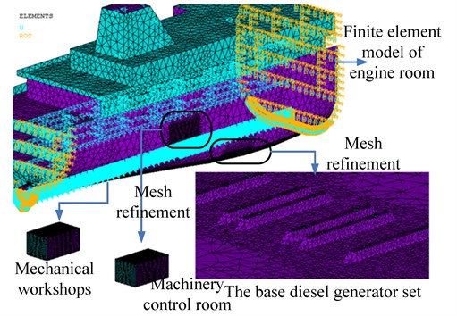
Fig. 15The FEM results of floating cabins
5. Effect of floating cabins design on vibro-acoustic characteristics of vessel engine room cabins
5.1. The analyses of the results of model calculation
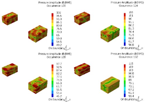
A closed cavity model is generated with the internal surface of the structural finite element model. Finally, the acoustic boundary element model is set up. Because the existence of the centralized control console, chairs and the ship power station has a great influence on the results, the influence of devices’ occupying the space should also be concerned and calculation should be carried out by the indirect boundary element method. According to the acoustic boundary element model which must meet the principle of a wavelength containing six grid cells, the model can analyze the frequency range which can be up to 200 Hz. The ministry of interior fluid is usually defined as the air under the conditions of the standard atmosphere, its density: 1.2 kg/m3. The results are input as the boundary conditions by using Virtual.Lab to make the sound field calculation. Fig. 16 shows sound pressure color nephogram of field point (12 Hz, 16 Hz, 20 Hz, 24 Hz), Fig. 17 shows sound pressure color nephogram of field point (120 Hz, 124 Hz, 128 Hz, 132 Hz). Because the constrained damping materials are laid on the NO. 1 AC, the sound pressure level in the NO. 1 AC was significantly less than the NO. 2 AC, as is shown in the Fig. 16 and Fig. 17.
Fig. 16Sound pressure color nephogram of field point (12 Hz, 16 Hz, 20 Hz, 24 Hz)
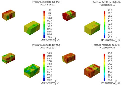
Fig. 17Sound pressure color nephogram of field point (120 Hz, 124 Hz, 128 Hz, 132 Hz)
5.2. Control on vibro-acoustic environment of vessel engine room
There are two ways of transmission of the noise in the cabin: sound travel through solid and air. If the solid transmission structure-borne noise (SBN) is the only concern, all plate vibro-acoustic characteristics in the cabin are the main factor to affect indoor noise. The structural panel which may have the greatest impact on the noise can be defined by the analysis of panel acoustic contribution, which is an important part and main approach of lowering noise. To reduce noise in the cabin and optimize the cabin panels, the vibration response in the mentioned cases is taken as the boundary conditions of the BEM. The right ear position of the duty engineer in the machinery control room is considered to be the response points to analyze panel acoustic contribution in the floating cabins. The key panel which has the significant influence is defined by calculating the acoustic contribution of panel. The panel vibration suppression is made according to the analysis results of response. As is shown in the Fig. 18, the Panel color bars contribution display of NO. 1 AC is able to illustrate clearly the acoustic contribution in different panels. FB, TP, LBHD and RBHD make great contributions to sound pressure level. The constraint damping materials are used to restrain the vibration of the panels. The materials of the floating floor consist of 2.0 mm special rubber and 2.0 mm galvanized steel sheet from the bottom up respectively, which provides a quality acoustic performance within the lowest height. In addition, it also concludes 40 mm mineral wool and 20 mm composite materials, which effectively lowers the noise that is caused by the impact damage and structural vibration. The ship’s TP or FB which makes great contributions should be selected and dealt with constraining damping materials.
Fig. 18Panel color bars contribution display of NO. 1 AC
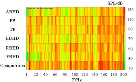
Fig. 19The sound pressure level curve of field point 1 and field point 2
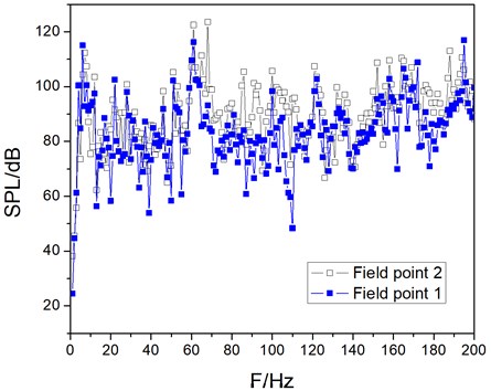
The changing conditions of sound pressure level in the field point 1 of the duty engineer right ear position in the NO. 1 AC and field point 2 of the duty engineer right ear position in the NO. 2 AC are shown as the Fig. 19. As we can see, after the damping materials are applied, the sound pressure level, especially between 55 Hz and 140 Hz, is lowered, which signifies the improvement of noise problem in the cabin. Only frequencies between 3-11 Hz, 17 Hz, and 172 Hz are higher than those in NO. 2 AC. That’s because the structures have resonance radiation to form a resonance peak. Additionally, the damping structures will massively restrain the vibration in 21 Hz, so the curve of sound pressure level hits the bottom point. The nature of acoustic contributions of different plates in the cabin can be identified through the analysis contributions of them. Plates that make great contributions to corresponding acoustic should be identified and constrained with damp to improve the noise problem.
6. Conclusions
The engine room is a vibration and noise source in the seafarers’ work areas or even living areas. A model was developed of the engine room with a floating cabin to predict SBN in ship cabins. To verify the accuracy and validity of the developed model, the predicted results were compared with corresponding experimental results, which comprised measurements carried out on a mock-up of a typical simplified cabin structure. Various floating cabin structures were studied, and the effects of variations in the isolator and constraint damping structure were investigated. The SBN could be controlled to some extent by varying any of prescribed parameters. Moreover, the developed model could be an effective tool for predicting SBN in ship cabins. This paper mainly studies the effects of auxiliary engine room alternator prime movers (auxiliary diesel engine) on the noise in the structure of cabin, establishes integration calculation model of cabin and considers stimulating dynamic load path of the ship. The FEM / BEM are applied to make calculations of vibration response and cabin vibration radiated noise. The upper deck that is the most close to the engine room is the main area to control the noise of area (the cabin location mentioned in the paper). Based on the analysis of the noise forecast report, the noise values of cabins in the upper deck, especially accommodation are generally exceeding the standard, so effective measures should be taken to control noise. Damping vibration can transfer the mechanical vibration energy into heat energy or other energy so as to achieve the purpose of reducing vibration by using the contribution analysis of cabin panel acoustic. To further study the damping vibration noise in the floating cabin, accurate acoustic model should be established. At the beginning of the ship design, the concept of the acoustic design can be considered throughout the ship design, according to the acoustics parameters. Quantitative technical indicators for noise control technology should be set up and the process of the control direction should be monitored to change from passive noise reduction to aggressive noise control.
References
-
Wang Yu, Chen Xing-lin, LI Guang-min Influence of vibration isolators to the vibration characteristics of a ship foundation. Ship Science and Technology, Vol. 34, Issue 1, 2012, p. 30-35, (in Chinese).
-
Jongsoo Lee, Chang Yong Song Hydroelastic effects in vibration of plate and ship hull structures contacted with fluid. International Journal of Ocean System Engineering, Vol. 1, Issue 2, 2011, p. 76-88.
-
Liu Xiao-ming, Wang Xiao-yu, Chen Ci-hui Numerical analysis of low and middle frequency noise in ship cabin using fluid- structure coupling. Journal of Ship Mechanics, Vol. 12, Issue 5, 2008, p. 812-818, (in Chinese).
-
Yu Da-peng, Zhao De-you, Wang Yu Influence of damped material and the ship model of acoustic on the ship cabin noise. Journal of Ship Mechanics, Vol. 14, Issue 5, 2010, p. 539-548, (in Chinese).
-
Sun-Il Cha, Ho-HwanChun Insertion loss prediction of floating floors used in ship cabins. Applied Acoustics, Vol. 69, Issue 2, 2008, p. 913-917.
-
Jee-Hun Song, Suk-Yoon Hong, Won-Ho Joo Analysis of structure-borne noise in ship cabins using a floating floor with an inserted viscoelastic layer. Journal of Marine Science and Technology, Vol. 14, 2009, p. 127-135.
-
Tongjun Cho Vibro-acoustic characteristics of floating floor system: The influence of frequency-matched resonance on low frequency impact sound. Journal of Sound and Vibration, Vol. 332, 2012, p. 33-42.
-
Sung-Hee Kim, Suk-Yoon Hong, Jee-Hun Song, Won-Ho Joo Interior noise analysis of a construction equipment cabin based on airborne and structure-borne noise predictions. Journal of Mechanical Science and Technology, Vol. 26, Issue 4, 2012, p. 1003-1009.
-
Zhu Xiang, Li Tianyun, Zhao Yao, Wei Qiang A calculation of the vibration and sound radiation of ship auxiliary engine room and its experimental research. Huazhong University of Science and Technology, Nature Science Edition, Vol. 33, Issue 10, 2005, p. 19-21, (in Chinese).
-
Zhang Lei, Cao Yue-yun, Yang Zi-chun,He Yuan-an Transmissibility matrix method for identification of ship noise source and corresponding test verification. Journal of Vibration Engineering, Vol. 26, Issue 2, 2013, p. 291-297, (in Chinese).
-
Xia Qi-qiang, Chen Zhi-jian Effect of bulkhead vibration on vibro-acoustic characteristics of ring-stiffened cylindrical shell. Journal of Naval University Engineering, Vol. 26, Issue 1, 2014, p. 23-28, (in Chinese).
-
Wang Lili, Li Shunming, Yu Guoqiang, Wang Qian The modeling of civil aircraft cabin and numerical simulation of radiation noise based on FEM/BEM. Machine Design and Manufacturing Engineering, Vol. 42, Issue 11, 2013, p. 10-13, (in Chinese).
-
Citarell R., Federico L., Cicatiello A. Modal acoustic transfervector approach in a FEM-BEM vibro-acoustic analysis. Engineering Analysis with Boundary Elements, Vol. 31, Issue 3, 2007, p. 248-258.
About this article
This work was financially supported by the Central University Basic Scientific Research Foundation.
