Abstract
The undesired hysteresis exists widely in smart-material actuators, which significantly reduces the accuracy and response speed of the actuators. In this paper, the static experiment of our previously developed hybrid vibration isolator (HVI) employing piezoelectric actuator is implemented to choose appropriate preload of the HVI. The preload-dependent hysteresis of the HVI is also proved in the static experiment. To achieve the hysteresis linearization control of the HVI, two linearization methods named the feedforward linearization and feedforward compensation and PI feedback hybrid linearization control are presented, respectively, which are based on the Bouc-Wen model and corresponding parameter identification model. To evaluate the effectiveness of the proposed linearization controllers for the HVI, the experiments are implemented. The experiment results demonstrate that both linearization controllers for the HVI can linearize the hysteresis characteristics and improve the HVI control accuracy. In addition, the feedforward compensation and PI feedback hybrid linear controller can achieve higher linearity than feedforward compensation controller.
1. Introduction
The smart-material actuators are widely used in active vibration isolation system, precision positioning platform and micro-/nano-technology, etc. Due to the advantages of fast response, high resolution, high precision, small size, no backlash, no friction and high output force, the piezoelectric actuators are widely used in mechanic engineering, vibration suppressors, positioners, precision instrument, biological engineering, medical diagnostics, MEMS technology, etc. [1-4]. However, the piezoelectric actuator exhibits non-linear hysteresis behavior, which seriously affects its precision and performance [5]. The complex hysteresis may generate the system errors, reduce the system precision and causes system instability. The hysteresis model and corresponding compensator should be established to reduce the effects of the hysteresis behavior and improve the system precision [6].
Compensators based on hysteresis model have been developed to characterize the hysteresis phenomenon and linearize the actuator, which are classified into open-loop compensator based on hysteresis model, compensator with closed-loop controller based on hysteresis model [7-10]. The main idea of the open-loop feedforward control is to establish a mathematical model to describe the hysteresis and implement a compensator based on the mathematical model to linearize the actuator [5]. Based on the open-loop feedforward control, the closed-loop control is implemented utilizing suitable sensors and control method. In the current literatures, simple PID controller [11], the sliding mode controller [12] and H∞ controller [13] are widely focused. Many adaptive controllers are proposed to cater to the system with hysteresis non-linearity [14, 15]. The closed-loop feedback control needs high-precision and high resolution sensor, which will inevitably increase the cost and decrease the response speed of the actuator, even bring instability to the whole system. Generally, the modelling for hysteresis behavior is crucial when the compensation controller is developed for the piezoelectric actuator. Many hysteresis modeling methods have been developed to describe the hysteresis character, such as curve-fitting method and mathematical models including the static and dynamic model. The Preisach model [16, 17] and Prandtle-Ishinskii model [18] of the static models are the widely used, which can describe hysteresis well but can’t simulate the dynamic characteristic of the smart-material actuators very well. The dynamic models describe the hysteresis by using nonlinear differential equations. The Bouc-Wen model of the dynamic model has been widely applied to simulate the hysteresis characteristics of structures in many fields [19-21], which can match the hysteresis behavior of the smart and intelligent materials very well. The Bouc-Wen model is established based on a set of nonlinear differential equations, which is suitable to apply in the compensator due to simplicity of computation and implementation [22].
In our previous work [23], a novel hybrid vibration isolator was proposed, where a piezoelectric stack actuator was employed as the active vibration isolation component. The preliminary results in our previous work indicated that our proposed HVI presented excellent vibration isolation performance. In order to enhance the control accuracy and response speed of the HVI, hysteresis linearization control of the HVI is proposed and explored, which is the main contribution of this paper. First, the mechanical design of the HVI is described. Then, the hysteresis model and parameters identification are established. The feedforward compensation controller and feedforward compensation & PI feedback linearization controller based on the Bouc-Wen model are designed. Finally, the controller prototypes and validation experiments are implemented. This paper concludes with discussions of the experiment results and expectations for future works.
2. Mechanical design of the HVI employing piezoelectric actuator
According the vibration isolation needs of microvibration and wide frequency band disturbances, simple passive vibration isolation is difficult to isolate the low frequency disturbances, and simple active vibration isolation may increase cost and bring in the instability problem. To synthesize advantages of the passive and active vibration isolation methods, a hybrid vibration isolation system is integrated with active and the passive vibration isolator. The hybrid vibration isolation system can use active control to change the inherent properties of the system, attenuate the low frequency disturbance and resonance peak of specific frequency point. At the same time, due to the actuator output bandwidth constraint, passive vibration can play a major role in attenuating high frequency disturbance to satisfy wide-band vibration isolation requirements.
A novel hybrid vibration isolator employing piezoelectric actuator is previously proposed in [23], whose mechanical structure is shown in Fig. 1. Actually, the components in Fig. 1 can be divided into two groups, i.e., the passive group and the active group. The two groups are connected in series to make full use of their vibration isolation performances. The passive group employs the vulcanized shear rubber due to its sample structure, high damper, easy metal bonding, which is responsible for supporting static loads and isolating the unwanted vibration over a wide frequency range. Compared with the traditional rubber block contacted with metal, the vulcanized shear rubber can reduce the structure gap and the influence of nonlinear characteristics (friction and collision). The active group employs the piezoelectric actuator due to its high resolution, high output force, fast response, no backlash and fiction, which can enhance the vibration performance at the specific frequencies such as the resonant frequencies, the exciting frequencies etc. Based on the vulcanized technique, the much lower stiffness of the passive rubber can be obtained to achieve lower natural frequency. The piezoelectric stack (type: XP 6×6/18 from Harbin Core Tomorrow Science &Technology Co., Ltd.) is the main component in the active vibration isolation. The regulation equipment and linear bearing outside of the force output rod are employed to guarantee the axial displacement of the piezoelectric stack. The pre-loaded spring is employed to guarantee piezoelectric stack always compressed to eliminate the radial displacement and the structure gap.
The compact HVI with slender rod exterior structure is suitable to install on multi degrees of freedom micro precision platform, which can reduce motion interference between legs and platform. In addition, the HVI actuated by 0-150 V voltage to provide 1400 N output force needs small energy consumption, which is a distinct feature and advantage when the HVI is used in the aerospace engineering. However, the hysteresis of our employed naked piezoelectric stack is shown in Fig. 2, which indicates that the maximum hysteresis is 11.2 %. The non-linear hysteresis behavior will affect the accuracy and response speed of the HVI, which is urgent to be solved.
Fig. 1The structure of the hybrid vibration isolator
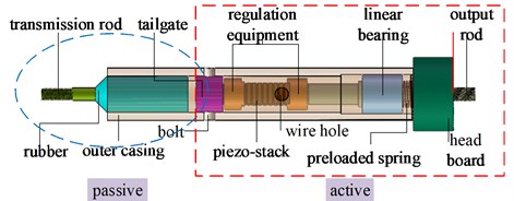
a) The schematic drawing of the HVI

b) The prototype of the HVI
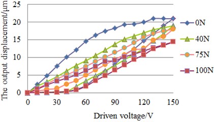
In addition, in order to determine the appropriate preload of the HVI, the static experiment is implemented. The spring preload can be changed by regulating the adjusting nut of the HVI. Corresponding to different groups of the preload, the driven voltage-output displacement curve can be measured. By comparing the hysteresis results with different preloads, the optimal spring preload can be obtained. Although, active vibration isolation requires that the actuator has the small hysteresis non-linearity and the large output displacement, the two sides are contradictory. The hysteresis and our desired output displacement reached a good balance when the preload is 75 N according to the Fig. 3. At last, the preload of the HVI is set as 75 N.
Fig. 2Hysteresis curve of the naked piezoelectric stack
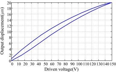
Fig. 3Static experiment result for the HVI with different groups of the preload
3. Hysteresis modeling and parameters identification of the HVI
The HVI is tested under the 60 Hz and 90 V sinusoidal driven voltage signal. The measured hysteresis curve between the output displacement and driven voltage of the HVI is shown in Fig. 4(a). The straight line based on the least squares fitting is considered to decompose the voltage-displacement curve. The output displacement can be considered as the summation of the linear component and the hysteretic component, which are shown in Fig. 4(b) and Fig. 4(c), respectively. Therefore, the output displacement of the HVI can be obtained:
where y(t) is the output displacement of the HVI. Z(t) and Y(t) are the hysteretic and linear components, respectively. v(t), y0 and kv are the driven voltage, the initial displacement without driven voltage and the ratio between the driven voltage and the output displacement, respectively.
The Bouc-Wen model [24] for HVI can be expressed as:
where ˙z(t) is the first-order derivative of z(t). A, n, β and γ are the model parameters of the Bouc-Wen model for the HVI.
Fig. 4Hysteresis curve of the HVI under 60 Hz sinusoidal voltage signal
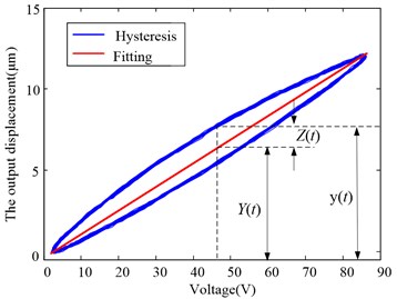
a) Least-squares fitting hysteresis curve
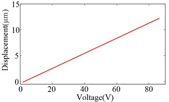
b) Linear components
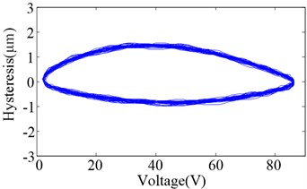
c) Hysteretic components
In order to use the Bouc-Wen model expressed by Eq. (1) and Eq. (2) to describe the hysteresis behavior of the HVI, the model parameters A, n, β and γ need to be identified. The output displacement of the HVI is zero in the initial condition, i.e., the HVI will be under the initial condition if the driven voltage disappears for a long time. Under the zero initial condition, two driven voltage u(t) and v(t) are applied to the HVI, respectively, which are related by v(t)=u(t)+q and ˙v(t)=˙u(t). The corresponding output displacements of the HVI are denoted as x(t) and y(t), respectively, which can be obtained based on Eq. (1):
where q is the offset of sinusoidal driven voltage signal, which is a constant.
Assuming a set of M sampling points ([x1, y1], [x2, y2],…, [xM, yM]) on the hysteresis curve are used, the parameter kv can be formulated based on the least-squares method:
The Bouc-Wen model for the HVI can be rewritten based on the Eq. (2):
where:
Considering z(t)=0 when v(t)=v0, the parameter A can be obtained according to Eq. (6):
When ˙v(t)>0, N sets of sampling points (v1, z1), (v2, z2),…, (vN, zN) are assumed on the hysteresis curve, which ensure that (0 <z1<z2<…<zN). The Eq. (6) can be adapted as:
Assume -(β+γ)>0, according to Eq. (8) and the least-squares, the following equations can be obtained:
Similarly, N sets of sampling points (vN+1, zN+1), (vN+2, zN+2),…, (v2N, z2N) are assumed on the hysteresis curve, which ensure (zN+1<zN+2<…<z2N< 0). The Eq. (6) can be expressed as:
Assume -(β+γ)<0, according to Eq. (10) and the least-squares, the following equation for the parameters β and γ can be obtained:
Based on the Eq. (10) and Eq. (12), the parameters β and γ can be formulated:
Based on the Eqs. (5), (7), (9), (13), (14), when input driven voltages are known and corresponding output displacements are measured, the parameters (kv, A, n, β and γ) of the Bouc-Wen mathematics hysteresis model for the HVI can be identified.
4. Feedforward compensation & PI feedback linearization control
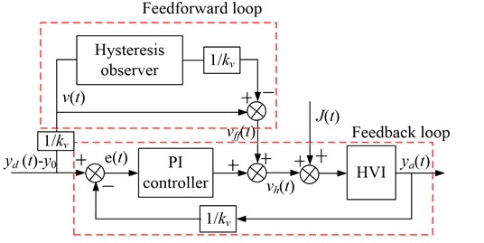
According to the foregoing the Bouc-Wen model for the HVI, the hysteretic displacement component can be compensated. In fact, the hysteresis of the HVI cannot be directly and accurately measured by the sensors. The hysteresis observer based on the Bouc-Wen model is necessary to forecast the hysteresis. Considering the driven voltage v(t), the feedforward linearization control voltage vff(t) can be obtained, when the relationship between driven voltage v(t) and output displacement y(t) is regarded as linear. According to the Eq. (1) and Eq. (2), we can obtain:
According to the Eq. (17), the vff(t) can be confirmed when the value of z(t) is obtained. When the feedforward compensation is established, the driven voltage v(t) is assumed as the feedforward linearization control voltage vff(t), then the hysteresis estimate ˆz(t) can be calculated. Then, the feedforward controlled voltage vff(t) can be derived as:
According to the Eq. (18), the linearity of the feedforward compensation control is determined by the hysteresis observer defined in Eq. (16). Assume that yd(t) is the desired output displacement and ya(t) is the actual output displacement, the error of the feedforward compensation control can be obtained:
According to the Eq. (19), the errors of the feedforward compensation control partially come from the Bouc-Wen model, the forecast hysteresis by the hysteresis observer, interference and noise. So, linearity of the HVI is not very well when feedforward control is used alone.
The feedback loop is necessary to be used for error correction. In order to further improve the linearization accuracy, the PI feedback loop is introduced into the linearization control. The feedforward compensation control is combined with PI feedback control, which is denoted as feedforward compensation & PI feedback hybrid linearization control based on the Bouc-Wen model. According to the block diagram of the feedforward compensation & PI feedback hybrid linearization control for HVI shown in Fig. 5, we can obtain:
=KP[v(t)-ya(t)kv]+KI∫[v(t)-ya(t)kv]dt+vff(t),
where vh(t) is hybrid linearization controlled voltage, KP is the proportion coefficient of the PI feedback controller and KI is the integral coefficient.
According to the Eq. (16) and Eq. (20), vh(t) controlled by the feedforward compensation & PI feedback hybrid linearization control can be obtained:
Feedforward control can compensate for the hysteresis component and PI feedback control can further compensate for the Bouc-Wen model error and restrain the interference. Then the linearity of the HVI can be further improved.
Fig. 5The block diagram of the feedforward compensation & PI feedback hybrid linearization control
5. Experimental verification
The experiments are implemented to validate the effectiveness of the Bouc-Wen model and hysteresis linearization controllers. Two kinds of the linearization control algorithm are established with MATLAB/Simulink of the real-time simulation system. The experiment setup is shown in Fig. 6, including piezoelectric actuator, piezoelectric ceramics controller, capacitance micrometer, Iotech data acquisition system, signal generator, oscilloscope, and real-time simulation system (based on MATLAB/Simulink and xPC). Piezoelectric ceramics controller (type: E00 from Harbin Core Tomorrow Science &Technology Co., Ltd.) can provide 0-150 V driven voltage to the HVI. The output displacement of the HVI is measured by the capacitance micrometer (type: NCDT 6500 contactless sensor from Micro-Epsilon Measurement Ltd.), whose repeatability and resolution are 0.6 nm and 0.15 μm, respectively. The feedforward compensation controller of the HVI is established in the MATLAB/Simulink. The feedforward control voltage is exported by real-time simulation control system to the piezoelectric ceramics controller driving piezoelectric actuator. The output displacement of the piezoelectric actuator is measured by the cap sensor and imported to the real-time simulation system. Based on the data processing and calculating, the output displacement is acted as feedback signal of the feedforward compensation & PI feedback hybrid linearization controller. The main difference between feedforward compensation controller and feedforward compensation & PI feedback hybrid linearization controller is whether the output displacement measured by cap sensor is the feedback variable.
According to the foregoing parameters identification method, the parameters of the Bcou-Wen model are calculated as follows: kv=0.148 μm/V, A=–0.774, β=0.1583, γ=0.042, and n=1.51. Using the Bouc-Wen model and parameters to predict the hysteresis of the HVI, the output displacement predicted and actually measured are shown in Fig. 7(a), the comparison of the hysteresis curve is shown in Fig. 7(b). The hysteresis behavior of the HVI can be predicted by the Bouc-Wen model and corresponding parameters identification method well.
Fig. 6The experimental setup for HVI
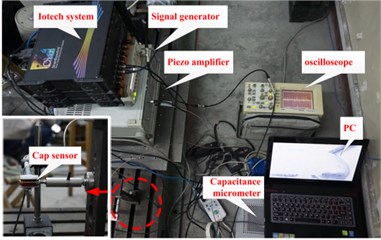
Fig. 7The comparison curve predicted by the Bouc-Wen model and measured by experiment
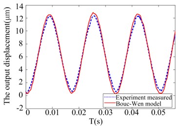
a) The output displacement in time domain
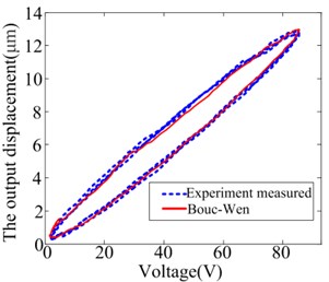
b) The hysteresis loop
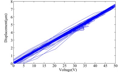
To verify the effectiveness of the feedforward compensation control, the voltage with corresponding desired output displacement is applied to the HVI for measuring the actual output displacement. The feedforward compensation control results are shown in Fig. 8(a), which shows the desired and actual output displacement. The error between the desired and actual output displacements is shown in Fig. 8(b). The relationship between driven voltage and output displacement with feedforward linear control is shown in Fig. 8(c). In order to quantify the performance of the linearization control method, the maximum error and the maximum relative error are defined:
where ya(max) is the actual maximum output displacement based on the experiment.
According to the data from Fig.8 and Eq. (22) and Eq. (23), the maximum error of feedforward compensation control is 0.8031 μm, and the maximum relative error is 4.015 %. The theoretical analysis for error sources is verified further. The errors are partly from the Bouc-Wen model, the forecast hysteresis by the hysteresis observer and interference and noise.
Fig. 8Feedforward compensation control results for the sinusoidal driven voltage
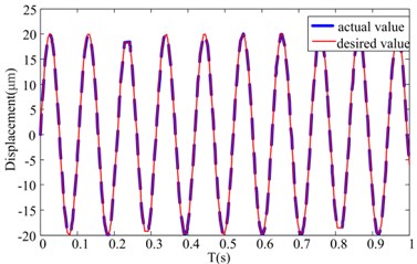
a) The actual and desired values in time domain
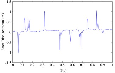
b) The error between the desired and actual output displacement
c) The relationship between the driven voltage and output displacement
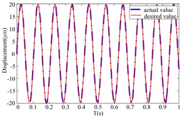
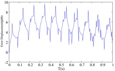
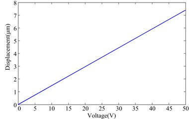
The results of the feedforward compensation & PI feedback hybrid linearization control based on the Bouc-Wen model are shown in Fig. 9. The output displacement and error in time domain are shown in Fig. 9(a) and Fig. 9(b), respectively. The relationship between driven voltage and output displacement is shown in Fig. 9(c). According to the Eq. (22) and Eq. (23), the maximum error and the maximum relative error of the hybrid linearization control are 0.052 μm and 0.26 %, respectively. The relationships between the output displacement and driven voltage of the HVI with the feedforward compensation & PI feedback hybrid linearization control are closed to be linear.
The performance comparison of different linearization controllers for the HVI is presented in table 1. Compared with the feedforward compensation control, the feedforward compensation & PI feedback hybrid linearization control can decrease the linearization errors of the HVI and greatly improve the control precision. The essential of the feedforward compensation & PI feedback hybrid linearization control is the superposition of the addition voltage onto the driven voltage. Part of addition voltage is generated by the feedforward control loop to compensate the hysteresis component in real time. Other part of addition voltage is generated by PI feedback control loop to compensate the errors of the feedforward control and eliminate the external disturbances. So, the feedforward compensation & PI feedback hybrid linearization controller for the HVI can achieve better linearity than feedforward linearization controller. However, the high accuracy and high resolution displacement sensor is necessary to realize the feedforward compensation & PI feedback hybrid linearization control, which not only increases the cost but also complicates the controller. The feedback loop may change the pole of the control system, which may result in the instability. The high frequency components imported by the feedback loop may affect the lifespan of the piezoelectric actuator. If the accuracy requirement is allowed, the feedforward linearization controller for the HVI is preferred.
Fig. 9Hybrid linear control results for sinusoidal driven voltage
a) The actual and desired values in time domain
b) The error between the desired and actual output displacements
c) The relationship between driven voltage and output displacements
Table 1Performance comparison of the different linearization controller of the HVI
Driven voltage | Control method | Maximum error | Non-linearity |
Sinusoidal voltage | Without control | 2.813 μm | 11.2 % |
Feedforward compensation control | 0.8031 μm | 4.015 % | |
Feedforward compensation & PI feedback hybrid linearization control | 0.052 μm | 0.26 % |
6. Conclusions
The natural hysteresis behavior between the output displacement and the driven voltage of the piezoelectric ceramic actuator restrict its application on high accuracy and resolution systems. A hybrid vibration isolator employing piezoelectric ceramic stack has been presented in our previous work, which features hysteresis characteristic similar to the other smart material actuators. In this paper, the static experiment result shows that the hysteresis loop of the HVI can be changed with different preload. In order to linearize the hysteresis of the HVI, the feedforward compensation control and feedforward compensation & PI feedback hybrid linearization control based on the Bouc-Wen model are presented and realized. According to the theoretical analysis, the errors of the feedforward compensation control limit the HVI to achieve better linearity. But the additional PI feedback loop can compensate the errors from the feedforward control and eliminate the external disturbances. Finally, in order to validate the effectiveness of the Bouc-Wen model and its parameters identification, experiments for the HVI are carried out. The experimental result indicates the Bouc-Wen model can predict the hysteresis behavior of the HVI well. In addition, in order to verify the performance of the feedforward compensation controller and hybrid linearization controller, the experiments are carried out based on the real-time simulation system and controller prototypes. Although the proposed controllers can linearize the hysteresis nonlinearity of the HVI, the linearization errors of the feedforward compensation control are more than the hybrid linearization control due to the modeling error of the Bouc-Wen model and the external disturbers. The feedforward compensation & PI feedback hybrid linearization controller for HVI can achieve better linearity.
To further improve the linearity and control accuracy of the HVI, much more works will be implemented to reduce the modeling error of the Bouc-Wen hysteresis model and more optimal control algorithm will be developed.
References
-
Tzou H. S., Lee H. J., Arnold S. M. Smart materials, precision sensors/actuators, smart structures, and structronic systems. Mechanics of Advanced Materials and Structures, Vol. 11, Issues 4-5, 2004, p. 367-393.
-
Devasia S., Eleftheriou E., Moheimani S. R. A survey of control issues in nanopositioning. IEEE Transactions on Control Systems Technology, Vol. 15, Issue 5, 2007, p. 802-823.
-
Niezrecki C., Brei D., Balakrishnan S., Moskalik A. Piezoelectric actuation: state of the art. The Shock and Vibration Digest, Vol. 33, Issue 4, 2001, p. 269-280.
-
Salapake S., Sebastian A., Cleveland J. P., Salapaka M. V. High bandwidth nano-positioner: a robust control approach. Review of Science Instrument, Vol. 73, Issue 9, 2002, p. 3232-3241.
-
Richter H., Misawa E. A., Lucca D. A., Lu H. Modeling nonlinear behavior in a piezoelectric actuator. Journal of the International Societies for Precision Engineering and Nanotechnology, Vol. 25, 2001, p. 128-137.
-
Xiao S. L., Li Y. M. Dynamic compensation and H-infinity control for piezoelectric actuators based on the inverse Bouc-Wen model. Robotics and Computer-Integrated Manufacturing, Vol. 30, Issue 1, 2014, p. 47-54.
-
Xiao S., Li Y. Modeling and high dynamic compensating the rate-dependent hysteresis of piezoelectric actuators via a novel modified inverse Preisach model. IEEE Transactions on Control Systems Technology, Vol. 21, Issue 5, 2013, p. 1549-1557.
-
Ang W. T., Khosla P. K., Riviere C. N. Feedforward control with inverse rate-dependent model for piezoelectric actuators in trajectory tracking applications. IEEE/ASME Transactions on Mechatronics, Vol. 12, Issue 2, 2007, p. 198-209.
-
Qin Y., Tian Y., Zhang D., Shirinzadeh B., Fatikow S. A novel direct inverse modeling approach for hysteresis compensation of piezoelectric actuator in feedforward applications. IEEE/ASME Transactions on Mechatronics, Vol. 18, Issue 3, 2013, p. 981-989.
-
Wolf F., Sutor A., Rupitsch S. J., Lerch R. Modeling and measurement of creep-and rate-dependent hysteresis in ferroelectric actuators. Sensors and Actuators A: Physical, Vol. 172, 2011, p. 245-252.
-
Xiao S., Li Y. Optimal design, fabrication and control of an XY micro-positioning stage driven by electromagnetic actuators. IEEE Transactions on Industrial Electronics, Vol. 60, Issue 10, 2013, p. 4613-4626.
-
Huang S. J., Chiu C. M. Optimal LuGre friction model identification based on genetic algorithm and sliding mode control of a piezoelectric-actuating table. Transactions of the Institute of Measurement and Control, Vol. 31, Issue 2, 2009, p. 181-203.
-
Xiao S., Li Y. Dynamic compensation and H∞ control for piezoelectric actuators based on the inverse Bouc-Wen model. Robotics and Computer-Integrated Manufacturing, Vol. 30, 2014, p. 47-54.
-
Zhou J., Wen C., Li T. Adaptive output feedback control of uncertain nonlinear systems with hysteresis nonlinearity. IEEE Transactions on Automatic Control, Vol. 57, Issue 10, 2012, p. 2627-2633.
-
Liu X., Wang Y., Geng J., Chen Z. Modeling of hysteresis in piezoelectric actuator based on adaptive filter. Sensors and Actuators, A: Physical, Vol. 189, 2013, p. 420-428.
-
Samuel I. The theoretical and experimental studies of a circular multi-layered annular piezoelectric actuator. Sensors and Actuators, A: Physical, Vol. 185, Issue 2, 2011, p. 280-287.
-
Kuhnen K., Krejci P. Compensation of complex hysteresis and creep effects in piezoelectrically actuated systems-a new Preisash modeling approach. IEEE Transactions on Automatic Control, Vol. 54, Issue 3, 2009, p. 537-550.
-
Tan U. X., Latt W. T., Shee C. Y., Riviere C. N., Ang W. T. Feedforward controller of ill-conditioned hysteresis using singularity-free Prandtl-Ishlinskii model. IEEE/ASME Transactions on Mechatronics, Vol. 14, Issue 5, 2009, p. 598-605.
-
Ismail M., Ikhouane F., Rodellar J. The hysteresis bouc-wen model: a survey. Archives of Computational Methods in Engineering, Vol. 16, Issue 2, 2009, p. 161-188.
-
Dominguez A., Sedaghati R., Stiharu I. Modeling and application of MR dampers in semi-adaptive structures. Computers and Structures, Vol. 86, Issue 3, 2008, p. 407-415.
-
Lu X., Zhou Q. Dynamic analysis method of a combined energy dissipation system and its experimental verification. Earthquake Engineering and Structural Dynamics, Vol. 31, Issue 6, 2002, p. 1251-1265.
-
Rakotondrabe M. Bouc-Wen modeling and inverse multiplicative structure of compensate hysteresis nonlinearity in piezoelectric actuators. IEEE Transactions on Automation Science and Engineering, Vol. 8, Issue 2, 2011, p. 428-430.
-
Zhang Y., Chen Z., Jiao Y. A hybrid vibration isolator: design, control, and experiments. Proceedings of I MechE Part C: Journal of Mechanical Engineering Science, Vol. 230, Issue 17, 2016, p. 2982-2995, https://doi.org/10.1177/0954406215604335.
-
Wen Y. K. Method for random vibration of hysteretic systems. ASME Journal of Engineering Mechanics Division, Vol. 102, Issue 2, 1976, p. 249-263.
Cited by
About this article
This research is funded by the National Natural Science Foundation of China (Grant No. 11172075) and National Basic Research Program of China (Grant No. 613235).

