Abstract
According to Katsuzo Nishi proposed capillarity exercise based on limbs vibrations the equipment to compensate obstruction of blood circulation is proposed. This equipment is composed from the vibrating bracelet for disable people and simplify exercise execution for healthy people as well. A need to create small size and low voltage device was identified. Previous studies have showed that it is recommended to avoid high frequencies because of possible harm for human. According to this requirements two high RPM, small size and low voltage motors were chosen. The rotors unbalances are working in beating regime, which increases the excentrical forces actuating human limbs. After processing gathered data proper frequencies for vibrating bracelet were chosen.
1. Introduction
Human’s vibration therapy date back to ancient Greece. It is becoming more frequently used nowadays to improve muscle strength, power and flexibility as well as coordination or even cardiovascular system. It is known that vibrations exercises have effect of helping to activate at suitable degree the various human organs [1]. It was determined that whole body vibrations affect increase of artery blood flow, heart rate and other physiological parameters [2, 3].
Katsuzo Nishi [4] introduced his Nishi system in 1927. It was based on his own studies and practice of what would amount to some 360 types of folk cures and health methods, both ancient and contemporary Oriental and Occidental. He included his own theories of dynamics of the human body based on the mechanical science. His theories are characterized by the idea that humans’ internal organs are basically the same as those evolved for the mammalian and human two-legged life style causes certain structural strains on the human bone structure. Nishi stated that the capillaries provide the true driving force of the circulatory system. To compensate obstruction of circulation in human’s limbs because of two-legged life he proposed the capillarity exercise. In paper [5] new models of the micro dosing elements are presented to investigate blood circulation in capillaries. On the strength of Nishi capillarity exercise it was decided to develop vibrating bracelet that could be used to execute exercise for disable people and to simplify this exercise for healthy people. The aim is to create small size and low voltage device because of direct contact with human. Another point that is important to take into consideration high frequencies has to be avoided. According to requirements mentioned earlier it was decided to choose two high RPM motors, make unbalances, investigate dynamics of one unbalanced motor and join two motors for beating excitation. Beating frequencies are used in various areas of new technologies. Similar technology of two small size vibrating motors found used as a miniature vibrotactile sensory substitution device for multifingered hand prosthetics [6] and two-micromotor platform design for actuating control of a novel sliding micro-robot [7]. The proposed application of beating frequencies is innovative.
The aim of this study is to identify proper regimes of coupled vibrating motors on beating phenomenon to use them on development of vibrating bracelet.
2. Capillary and vibration training
There were made number of studies related to vibration’s influence on human’s cardiovascular system and muscle strength. Previous studies of Institute of training science and sport informatics has showed that vibration training is an effective training method in order to improve maximal strength and flexibility. There was also identified that more capillaries are probably opened in order to keep a necessary level of cardiac output needed for the body. This might be one of the reasons for the various potential beneficial effects of vibration training. For the further studies it is important to know that in some cases blood vessels could be treated as a rigid tubes and the blood could be treated as incompressible uniform Newtonian fluid [8]. The positive effect of training capillarity could be proved that the mechanical equivalent of heat for kinetic energy and pressure of blood flow is reported that high speed (sometimes turbulent) blood flow enters to the capillary vessels, and the energy of blood flow turns into heat by frictions (collisions), and therefore, pressure of blood flow decreases approximately up to zero at the vena cava and the entrance of the right atrium [9]. Results following 10 minutes of vibration therapy on Laser Doppler studies revealed a consistent increase in blood supply [10]. Earlier studies shows relation between vibration training and blood circulation. Concentrating on capillaries and including Katsuzo Nishi theories new device and methodology have been created.
3. Methods
The capillarity exercise (Fig. 1) should be kept up for one or two minutes. As this exercise gives rise to capillarity in the limbs and draws the blood there, it naturally follows that the improvement of the general blood circulation will ensure [1]. Vibrating bracelet is developed for the disable people as a tool for executing this exercise without muscle effort. It could be used for healthy people as well to simplify this exercise and enhance concentration on vibration training eliminating actuating of muscles. The main part of vibrating bracelet consist of two small size, low voltage vibrating motors with unbalanced masses.
Fig. 1The capillarity exercise
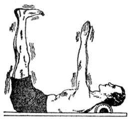
Fig. 2Motor with unbalanced mass system scheme
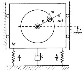
It was considered that spring-mass system was constrained to move only in vertical direction and excited by unbalanced rotating mass (Fig. 2). Here is the displacement, is the mass of the eccentric mass and is the distance from the motor shaft to the centre of the eccentric mass. is usually called eccentricity (). is angular velocity and is bulk mass of whole system. Then the equation of motion is:
The generated force can be calculated from the equation below:
Two identical unbalanced masses were used to create beating phenomenon. Beats are observed when two sine functions with near-equal frequencies are superimposed. The forced solution for undamped vibration features two superimposed frequencies. When frequency ratio , the solution is approximately:
4. Platform and equipment
To create unbalance forced vibrations on the limbs it was decided to choose two motors with high RPM parameter. According to the low price, small dimensions and electrical parameters it was chosen JOHNSON 20703 motor. Below main parameters of this motor are given (Table 1).
Table 1JOHNSON 20703 motor parameters
Name | Value |
Voltage | 3-13 V |
Current | 0.24 A |
RPM | 2989-5977 |
Rotor dimensions | 13×2 |
Motor dimensions () | 31×24 |
There is no data given about motor’s RPM dependence on voltage. These parameters are crucial calculating rotor’s unbalance created force. To identify these parameters it was made short experiment registering motor’s RPM at different voltage values. Values were registered with photo tachometer/stroboscope.
To create vibrations with unbalance there were made two identical masses that were fixed on the rotors of chosen motors. Mass with unbalance was projected with Solidworks software and it was made from AISI 1020 steel. The aim is to create as big force as possible and therefore masses were limited only by the free space by the rotor with unbalance mass beside. Main parameters are given below (Table 2).
Table 2Unbalance mass parameters
Name | Value |
Bulk mass | 14.86 g |
Mass without unbalance | 5.95 g |
Unbalance mass | 8.91 g |
Whole diameter | 7.5 mm |
Diameter without unbalance | 4.5 mm |
Diameter by the middle of unbalance | 6 mm |
Motors were fixed together linearly without an ability to move even at the high vibrations. Motors were screwed on beam that was created from glass-cloth laminate (HGW). The beam’s fixing holes were drilled at different length (5 cm and 10 cm) to observe differences on vibrations regarding to the beam length. Motors were screwed by the end of this beam. Primary experiments were made without any damping element. A damping box with water and air packages was created for the further experiments to eliminate any possibility of beam resonance (Fig. 3).
Motors and vibrations measuring sensor were fed by three power suppliers. Inductive displacement sensor IFM IG6084 was used to measure beam’s vibrations. All data was registered by the Oscilloscope Picoscope 3424 and the PC software PicoScope 6. Motors (revolutions per minute) parameters were registered with photo tachometer/stroboscope Lutron DT-2259. Temperature on the hand was monitored with FLIR A655 sc thermovisor.
Fig. 3a) Principal scheme of the vibrating platform and measuring elements; b) Vibrating motors on the beam with damping element and displacement sensor on the top
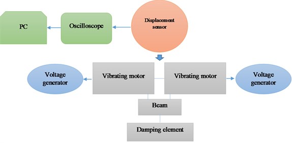
a)
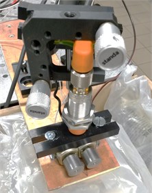
b)
5. Experiment protocol
Motor’s RPM measurements on the different voltage values were made with tachometer/stroboscope device. Measured voltage range: from 4 V to 16.5 V, with 0.5 V step. Values were measured in both regimes (tachometry and stroboscope) to get validated data. Measurements were made on both motors and the results showed no significant difference.
Investigation on forces created from small size motor were made on different voltage range from 4 V to 16 V with 0.1 V step. 4 V is motor starting voltage. This value is higher than given in datasheet because of the mass fixed on rotor. Experiment on measuring RPM values has showed that 16 V is the highest voltage value where top RPM limit is reached. First series of experiments were made without any damping element. Before starting the experiment beam natural frequencies were identified.
Secondly experiments with two motors were made. The voltage for each has been changed from 4 V to 16 V with 0.1 V step. This series of experiments were made without damping element as well.
To eliminate beam’s natural frequencies damping element was made. Motors were supplied by the same range of voltage as it was during the experiment without damping element. Gathered data were processed and grouped into three different categories depending on high and beam frequencies. Generated forces were calculated according to processed data.
6. Results
First, the rotor’s RPM dependence on the supplied voltage was identified (Fig. 4). The results has showed almost linear dependence. Motor starts to rotate at 4 V with 1370 rev/min. Every 0.5 V step RPM increases for approximately at 200 rev/min. At 16.5 V motor’s rotor reaches nearly highest value given in the datasheet – 5960 rev/min.
Fig. 4RPM dependence on voltage
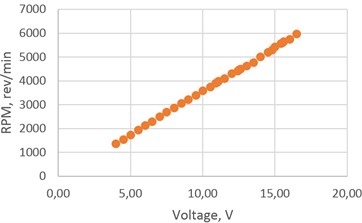
Fig. 5One motor vibrations
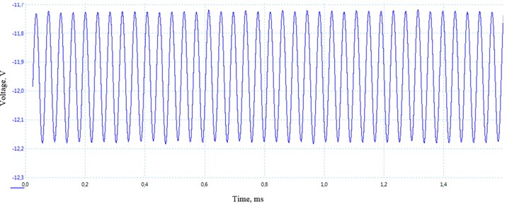
Next, experiment with one motor fixed on the beam was made. Gathered data on different voltage values disclosed that vibrating frequencies were almost the same independently from the supplied voltage. These results have showed that one motor was not able to go out of beam’s resonating frequencies. The value of 25 Hz were calculated with shorter beam (5 cm length) at voltage range from 4 to 6.5 V (Fig. 5). When system is out of resonance one motor was not able to generate force that would be high enough causing beam vibrations. Values were different with longer beam (10 cm length) but these were not analyzed because of resonance.
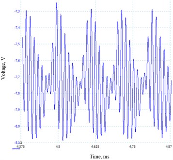
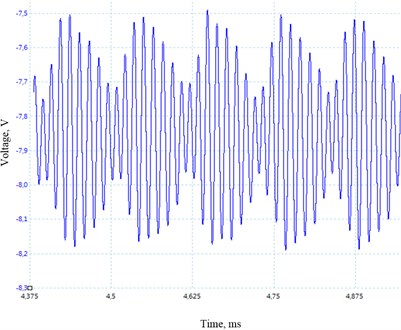
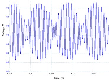
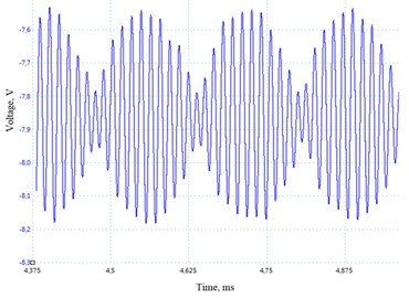
Fig. 6Two motor vibrations without damping: a) at 10 Hz (14.5 V – 11 V); b) at 8 Hz (12.5 V – 10 V); c) 6 Hz (12 V – 10 V); d) 2 Hz (11.5 V – 10 V)
a)
b)
c)
c)
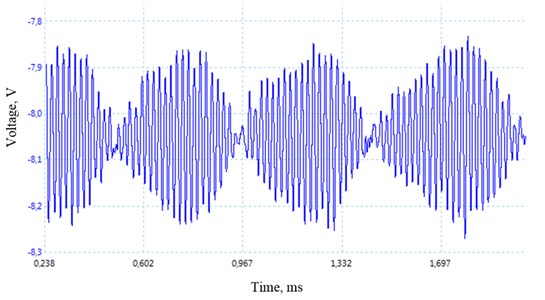
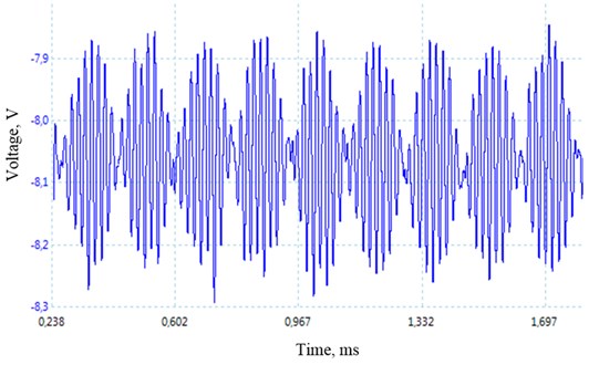
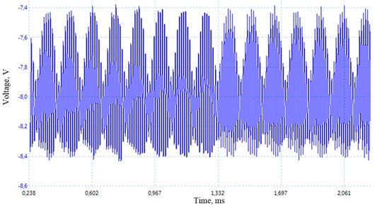
Fig. 7Two motor vibrations with damping: a) at 2 Hz (8V – 8 V); b) at 6 Hz (9.5 V – 8.5 V); c) at 8 Hz (14.8 V – 14.8 V)
a)
b)
c)
After completing experiments with one motor another was fixed linearly. The most appropriate results on experiment with two motors were collected on higher voltage values (Fig. 6). Lower values did not allow system exit from resonance. Processed results showed demand of verification using a damping element. Beam without damping element was moving in the range of 13 mm displacement during the beating frequency phenomenon.
Further experiments with damping element have showed that system generates enough force to overcome damper force and systems wasn’t allowed to enter resonance (Fig. 7). The amplitude of beam movement was up to 5 mm during the beating phenomenon. These results have proved that platform could be used for further experiments imitating human’s hand.
Force was calculated for each voltage combination with damping element. The values were divided into three groups according to the higher frequency value that could be used without harm [11]. The first group, values up to 50 Hz, second – from 51 Hz to 80 Hz and third, from 81 Hz to 100 Hz. Calculated forces that were generated from two vibrating motors in the first group were from 3.31 N to 11.54 N. The second group started from 12.32 N up to 28.08 N. And the third, from 26.29 N to 41.48 N. Values in the safest first group have showed that are high enough to generate limbs vibrations using bracelet with two motors used during the researches. This is new method and needs to be approved investigating blood circulation.
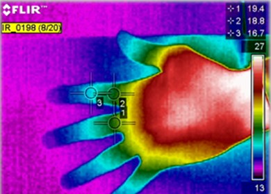
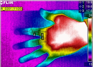
To investigate vibrating frequencies influence there were made experiments monitoring physiological parameters before and after the capillarity exercise. Significant changes were registered on ECG and respiratory graph as well as blood pressure raise [12]. An investigation monitoring temperature changes in the hands’ fingers were made giving vibratory movement at 6 Hz frequency. Temperature changes were registered with FLIR A655 sc thermovisor. The temperature were monitored on the both side of hand. There were registered 0.8 oC (Fig. 8) positive changes on the palm and 0.7 oC raise on the other side of the hand. Experiments were repeated ten more times and the results were very similar. These results shows that coupled motors with unbalance giving beating frequency phenomenon could be used for the imitation of capillarity exercise and is a new approach.
Fig. 8Palm temperature on three points: a) before the experiment; b) after the experiment
a)
b)
7. Future works
Regarding to the experiment results it was decided to prepare cardiovascular system imitation stand including peristaltic pump, pressure gauge, artificial blood vessels as well as capillaries and beam with coupled unbalanced motors. This stand will be a tool to identify vibrations influence in blood pressure changes on vessels and capillaries as well as other liquid parameters changes that are affected by the pre described vibration. Parallel to this in the near future it is planned to have a stand that would allow to make an imitation of the capillarity exercise without a human’s effort. The mechanical device would vibrate all four limbs and that would allow identify influence of isolated vibrations effect excluding muscle effort.
According to the results of earlier described experiments it was decided to develop vibrating bracelet as a new device that would allow to execute capillary exercise for disable people. Further experiments with fixed skin rheology measuring device [13] on human’s hand are planned to accomplish. Identified regimes of the motors will allow to generate correct vibrations on human’s limbs eliminating possible harm that could be caused by high frequencies. That would allow to gather physiological parameters’ changes and execute further researches.
References
-
Ailments Prevent sickness maintain health treat nishi system.
-
http://www.nishiusa.eurocontrol.biz/index.php?div_id=4&sub_id=13.
-
Amy Mark, Maureen MacDonald, Mark Rakobowchuck, Christopher Gordon, Cameron Blimkie Metabolic and cardiovascular responses during whole body vibration (WBV) exercise: a pilot study. Hamilton: Department of Kinesiology and Department of Radiology, McMaster University, 2002.
-
Yusuke Osawa, Yuko Oguma. Effects of whole body vibration on physiological responses to one bout of resistance training. Kanagawa: ASEP, Vol. 14, 2011.
-
Katsuzo Nishi – Wikipedia. http://en.wikipedia.org/wiki/Katsuzō_Nishi.
-
Arvydas Palevicius, Kazimieras Ragulskis, Algimantas Bubulis, Vytautas Ostasevicius, Minvydas Ragulskis Development and operational optimization of micro spray system. Proc. of SPIE, Vol. 5390, 2004, p. 429-438.
-
Cipriani C., D'Alonzo M., Carrozza M. C. A miniature vibrotactile sensory substitution device for multifingered hand prosthetics. Biomedical Engineering, Vol. 59, Issue 2, 2012, p. 400-408.
-
Vartholomeos P., Papadopoulos E. Analysis, design and control of a planar micro-robot driven by two centripetal-force actuators. IEEE International Conference on Robotics and Automation, 2006, p. 649-654.
-
Mester J., Kleinoder H., Yue Z. Vibration training: benefits and risks. Journal of Biomechanics, Vol. 39, Issue 6, 2006, p. 1056-1065.
-
W. S. Topham Comparison of methods for circulation of left ventricular stroke volume. Journal of Applied Physiology, Vol. 27, 1969, p. 767-769.
-
Ryan T. J. The effect of mechanical forces (vibration or external compression) on the dermal water content of the upper dermis and epidermis, assessed by high frequency ultrasound. Journal of Tissue Viability, Vol. 11, Issue 3, 2001, p. 97-101.
-
Cardinale M., Wakeling J. Whole body vibration exercise: are vibrations good for you? British Journal of Sports Medicine, Vol. 39, Issue 9, 2005, p. 585-589.
-
Venslauskas M., Ostasevicius V., Marozas V. Limb’s vibrations exercise monitoring with MEMS accelerometer to identify influence of cardiovascular system. Vibroengineering Procedia, Vol. 1, 2013, p. 48-52.
-
Benevicius Vincas, Gaidys Rimvydas, Ostasevicius Vytautas, Marozas Vaidotas Identification of rheological properties of human body surface tissue. Journal of Biomechanics, Vol. 47, Issue 6, 2014, p. 1368-1372.
About this article
This research work was funded by EU Structural Funds project “In-Smart” (Nr. VP1-3.1-ŠMM-10-V-02-012), Ministry of Education and Science, Lithuania.
