Abstract
This work presents the analysis, simulation of a conical resonator of a novel vibratory gyroscope called Bell Vibratory Gyroscope (BVG). The governing equations of motion are derived based on Love’s approximation and the mode frequencies and mode shapes are obtained by Finite Element Method (FEM). In order to investigate the character of the resonator under high axial impact loading, an impact dynamic model is established using FEM software. A 20,000 g permanent axial impact loading is applied on the resonator .The results show that the max Von Mises stress of the resonator is much smaller than the yield strength of the material which means the plastic deformation of the resonator will not occur. Experiment is carried out for verifying the effectiveness of Finite Element Method.
1. Introduction
Gyroscope is a sensor that measures the rate or the angle of rotation. All vibratory gyroscopes use the Coriolis acceleration that arises in rotating reference frames to measure rotation. The Coriolis forces produced by vibration of the sensing element and rotation of the system cause a transfer of energy between two of the gyro’s modes of vibration [1]. They have no rotating parts and have some advantages such as small size, high operation accuracy, low cost, low power consumption, long life, and especially good shock resistance comparing with fiber-optic gyroscopes, ring laser gyroscopes, and conventional rotating wheel gyroscopes [2]. However, it is still a problem that a vibratory gyroscope cannot work in extremely harsh environment such as the launch process of projectile [3]. In this situation, the most common failure mechanism due to shock is fracture. As the vital component of a vibratory gyroscope, the resonator has to be survived the shock. So it is very necessary to analyze the characteristics of the resonator under high impact. There are a number of different resonators including hemispherical resonators, cylindrical resonators, ring resonators and so on [4]. Hemispherical resonators cannot bear high impact because they are made of quartz although the HRGs based on them have achieved inertial navigation performance levels [5]. Innalabs Holding and Watson industries are developing and manufacturing CVG based on metallic cylindrical resonators which can survive thousands of g’s shock [6-9]. It is a pity that no detail research can be found in their open literatures. A new member of Vibratory gyroscopes, the bell-shaped vibratory angular rate gyro (abbreviated as BVG) using a parabolic shell as the resonator which can bear a 20,000 g axial impact according to the FEM simulation [8]. In addition, the characteristics of four different resonators under high impact loading mentioned above are compared in [10, 11], and the results show that the parabolic resonator has the best shock resistance. Unfortunately, because the fabrication of the parabolic resonators and attaching PZT elements are not conveniently and time consuming, the implementation of gyros based on it is difficult. As considering about the points above, a truncated conical metallic shell is proposed to be the resonator instead of the parabolic shell in this paper. The governing equations of the resonator are obtained based on the Love’s first approximation. The nature frequencies and mode shapes of the resonator are calculated by using FEM simulation, and the anti-high impact ability of the resonator is also analyzed by using FEM simulation. To examine the shock resistance or anti-impact ability, practical test is carried out as well as verifying the effectiveness of the simulation finally.
2. Gyro description
2.1. The structure of a conical resonator
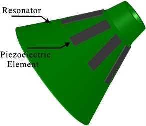
The truncated conical resonator of the BVG is shown in Fig. 1. The dimension of the resonator is millimeter-scale and one end of the shell is open. Eight piezoelectric elements used as electrodes are glued to the wall of its outer surface. The vibration of the conical wall is converted to voltage signal via the electrodes. Hence the glue connecting the outer surface and the electrodes should be electric and strong. The electrodes are exactly separated from each other by 45°. The thickness of the electrodes is much smaller than that of the conical wall. Thus the shell structure can be easily driven by the piezoelectric electrodes. The resonator is made of metal for the reason that can bear higher impact than other materials such as fused silica which has a huge Q factor. For the sake of modern metallurgy, a number of special alloys providing both high stability of alloy parameters to temperature changes and high Q-factor. For example, Ni45CrTi, a kind of alloy doped with Co and Mo having a temperature coefficient of frequency lower than 5×10⁻⁶ Hz/°C and, at the same time, a high temperature stability of Young’s modulus [7]. The material of the piezoelectric elements is PZT5A which having stable piezoelectric constants. All these features above ensure the novel conical resonator vibratory gyroscope has the potential of high Q-factor, high sensitivity and high performance.
Fig. 1Schematic of a truncated conical resonator
2.2. Working principle
The same as hemispherical resonators and cylinder resonators, the working principle of the gyroscope based on the conical resonators is utilizing the inertia effect of the standing wave in two vibration modes of the axisymmetric resonator caused by the Coriolis force. The two vibration modes are orthogonal called drive mode and sense mode, which are separated from each other by 45°. The drive mode and the sense mode are shown in Fig. 2(a), Fig. 2(b) respectively.
The conical resonator has maximum vibration amplitudes at four antinodes and zero vibration amplitude at four nodes. The vibration mode axes, including two antinodes axes and two node axes, which are 45° apart from each other, are the inherent characteristic axes of the resonator and will determine the positions of the vibration modes. For a perfect conical resonator without any manufacturing errors, the drive mode and sense mode have the same natural frequency. When working, the drive mode is excited by two symmetric piezoelectric elements, for example, piezoelectric elements 1 and 5, to vibrate at its natural frequency with constant amplitude; the electrodes at the node axis will sense no signal for a perfect conical resonator. When the conical resonator is rotated around its axis of symmetry, the sense mode will be excited to vibrate and the piezoelectric elements 2 and 6 at the node axis will generate a signal proportional to the rotation rate with the same frequency as that of the drive mode. However, imperfections or uneven mass distributions are inevitable in the practical point of view. The natural frequencies of drive mode and sense mode will not be the same which will cause so called frequency split. It may results in significant factors diminishing accuracy and vibratory performance of the resonator. Hence, for an imperfect resonator, an angle determined by the frequency split will be appearance between the ideal vibration mode axes and exciting ones. In this situation, the electrodes at the node axis will sense the signal coupled with antinode one. Moreover, the coupled error will be introduced into the calculation of angular rate. Fortunately, the error signal can be compensated by applying controlled force on the electrodes at the node axis such as 4 or 8.
Fig. 2Schematic of the working principle
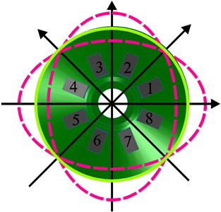
a) Drive mode
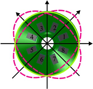
b) Sense mode
2.3. Theoretical consideration
In order to obtain the nature frequencies and mode shapes of the resonator, the governing equations of motion have to be established. The coordinate system is shown in Fig. 3, which is given by Hua Li [12].
Fig. 3The geometry of a truncated conical shell
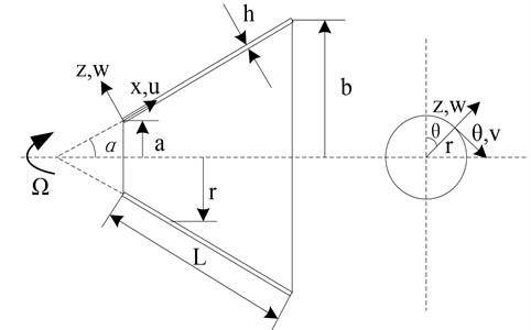
The reference surface of the conical shell is taken to be at its mid-surface where an orthogonal co-ordinate system (x, θ, z) is located and r is the radius at co-ordinated point (x, θ, z), and the displacement fields of the conical shell in the x, θ and z directions are denoted by u, v, and w respectively. Based on the linear approximation, the governing equations of motion for a truncated circular rotating conical shell without considering the centrifugal force effect can be derived directly as following [10]:
In the expression, ρ is the density of the conical shell, α the cone angle, and Ni and Mi the force and moment resultants, respectively. Ni and Mi can be represented by:
The geometric relations of deformations for the reference surface of the rotating conical shell can be written as:
e2=1r∂v∂θ+usinα+wcosαr,
e12=1r∂u∂θ+∂v∂x-vsinαr,
k1=-∂2w∂x2,
k2=-1r2∂2w∂θ2+cosαr2∂v∂θ-sinαr∂w∂x,
k12=2(-1r∂2w∂x∂θ+sinαr2∂w∂θ+cosαr∂v∂θ-vsinαcosαr2).
In the expression, e1 and e2 are the strains of the reference surface in the meridional direction and in the circumferential direction, respectively, e12 is the shear strain of the reference surface and k1, k2 and k12 are the reference surface curvatures, respectively.
Assume that the displacements of the conical shell take the following form for free vibration:
v(x,θ,t)=V(x)sin(nθ+ωt),n=0,1,2,…,
w(x,θ,t)=W(x)cos(nθ+ωt),
where n is the wave number in the circumferential direction, and ω is the nature frequency. Thus, based on Love’s first approximation theory, and the mode shapes can be obtained by using DQ method, GDQ method, Rayleigh-Ritz method and so on [12-14].
3. Simulation
In this work, the FEM (finite element method) software is used to obtain the modal frequencies, the mode displacements distribution and the characteristics of the resonator under high axial impact loading.
3.1. Model analysis
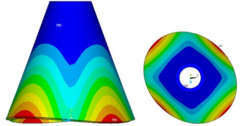
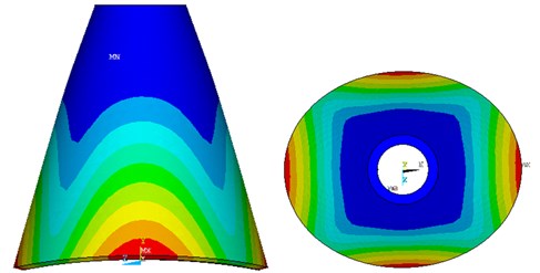
The main structure parameters of the conical resonator are as follows: a=3.5 mm, b=11 mm, h=0.7 mm, α= 25°; as shown in Fig. 2. The material parameters and simulation condition is followed in Table 1. The modal analyzed results show the work mode shapes interested in Fig. 4. The drive mode frequency is 7848 Hz, which is coincident with the sense mode. The equivalent frequency of the drive mode and sense mode enables the Coriolis force to induce the sense mode of high sensitivity.
Table 1The parameters with simulation
Name of the parameters (Unit) | Value |
Material | Ni43CrTi |
Density (kg/m3) | 8170 |
Poisson’s ratio | 0.3 |
Young modulus (GPa) | 196.76 |
Yield strength (MPa) | 500 |
Mesh generation method | Free |
Release ratio | 1E-4 |
Fig. 4The results of mode analysis
a)
b)
According to the modal contour of the FEM model, we can find the desired drive mode and sense mode of the resonator. It is proved that the resonator can be used as a vibratory gyroscope.
3.2. Impact analysis
The benefit of BVG is the ability to load a high impact, which can adapt well to the extremely harsh environment. As the core component of the BVG, the shock resistance of the conical resonator represents the survival ability of the BVG. However, the exact dynamic model of the conical resonator under impact is not easy to be established Based on this point, a 20,000 g permanent axial impact loading is applied on the resonator to verify whether the plastic deformation occurred or not. The simulation condition is the same as the Table 1, and the stress cloud chart are shown in Fig. 5.
Fig. 5Stress cloud chart of the conical resonator
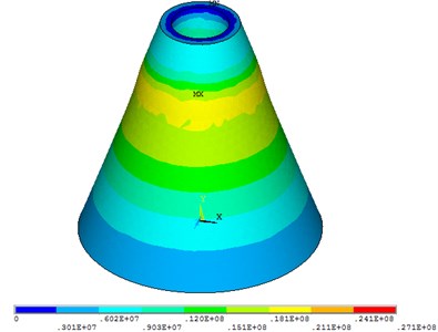
The result shows that the maximum stress is 27.1 MPa which is much smaller than the yield stress of the material 500 MPa. According to Von Mises criterion, during the impact process, the resonator produces a small deformation and it is quickly restored after the impact. It means that the conical resonator has very good shock resistance.
4. Experiment and discussion
In order to verify the effectiveness of Finite Element Method, practical test is carried out using a shock tester. The conical resonator is fixed on the platform of the shock tester shown in Fig. 6.
Fig. 6The platform of the shock tester
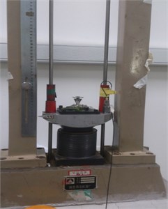
Raising the platform up to a specified height and dropping it freely. The impact curve is shown in Fig. 7 and the frequency characteristics chart is shown in Fig. 8 and Table 2.
Fig. 7Impact curve
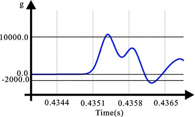
Fig. 8Frequency characteristics chart
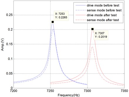
Table 2Frequency characteristics before and after test
Nature frequency (Hz) | Frequency split (Hz) | ||
Drive mode | Sense mode | ||
Before test | 7253 | 7253 | 0 |
After test | 7307 | 7307 | 0 |
As seen from the Frequency characteristics chart and Table 2, for the conical resonator, although the natural frequencies are moved to higher value due to the impact, the frequency split is not changed. It means that the gyroscopic effect of the conical resonator is still strong and the main performance will not be changed. The conical resonator has a very good potential of surviving shock.
5. Conclusion
In this paper, the characterization of a conical resonator of a BVG under Axial Impact is investigated. The working principle of the conical resonator is described. Then, the modal frequencies and the mode shapes of the drive mode and sense mode are obtained by using FEM simulation. After that, a 20,000 g permanent axial impact loading is applied on the resonator to verify whether the plastic deformation occurred or not by utilizing the FEM simulation, too. Practical test is carried out for verifying the effectiveness of Finite Element Method finally. Both the simulation and practical results show that the conical resonator has the ability to against the high impact and has great potential to solve the problem of using gyroscopes in extremely harsh environment.
References
-
Shkel A. M. Type I and Type II micromachined vibratory gyroscopes. Proceedings of IEEE/ION PLANS – Position, Location, and Navigation Symposium, San Diego, CA, USA, 2006, p. 24-27.
-
Lynch Coriolis D. D. Vibratory gyros. Proeedings of Symposium Gyro Technology, Stuttgart, Germany, 1998.
-
Vinod Chakka, Mohamed B. Trabia, Brendan O’Toole, Srujanbabu Scridharala, Samman Ladkany, Mostafiz Chowdhury Modeling and reduction of shocks on electronic components within a projectile. International Journal of Impact Engineering, Vol. 35, 2008, p. 1326-1338.
-
Tao Y., Wu Xuezhong, Xiao Dingbang, et al. Design, analysis and experiment of a novel ring vibratory gyroscope. Sensors and Actuators A: Physical, Vol. 168, Issue 2, 2011, p. 286-299.
-
Xiang Xia, Yulie Wua, Xiaomei Wua, Yi Taoab, Xuezhong Wua Investigation on standing wave vibration of imperfect resonant shell for cylindrical gyro. Sensors and Actuators A: Physical, Vol. 13, 2012, p. 10123-10150.
-
Rybak F. J. Comparison of hemispherical resonator gyro and optical gyros. IEEE Aerospace and Electronic, Vol. 7, 1992, p. 40-45.
-
Chikovani V. V., Okon I. M., Barabashov A. S., Tewksbury P. A set of high accuracy low cost metallic resonator CVG. Proceedings of the Position, Location and Navigation Symposium, Monterey, CA, USA, 2008, p. 238-243.
-
Watson W. S. Vibratory gyro skewed pick-off and driver geometry. Proceedings of the Position Location and Navigation Symposium, Indian Wells, CA, USA, 2010, p. 171-179.
-
Watson W. S. Improved vibratory gyro skewed pick-off and driver geometry. Proeedings of Symposium Gyro Technology, Stuttgart, Germany, 2006.
-
Su Z., Fu M., Li Q., Liu N., Liu H. Research on bell-shaped vibratory angular rate gyros character of resonator. Sensors, Vol. 13, 2013, p. 4724-4741.
-
Ning Liu, Zhong Su, Qing Li Characterization of the bell-shaped vibratory angular rate gyro. Sensors, Vol. 13, 2013, p. 10123-10150.
-
Lam K. Y., Hua L. Vibration analysis of a rotating truncated circular conical shell. International Journal of Solids and Structures, Vol. 34, 1997, p. 2183-2197.
-
Shu C. An efficient approach for free vibration analysis of conical shells. International Journal of Solids and Structures, Vol. 34, 1995, p. 935-949.
-
Feng-Ming Li, Kikuo Kishimoto, Wen-Hu Huang The calculations of natural frequencies and forced vibration responses of conical shell using the Rayleigh-Ritz method. Mechanics Research Communications, Vol. 36, 2009, p. 595-602.
About this article
The authors would like to thank the Beijing Key Laboratory of High Dynamic Navigation Technology, University of Beijing Information Science and Technology, China, for equipment access and technical support. This work was supported by National Natural Science Foundation of China (Grant No. 61031001).
