Abstract
A data acquisition system for Computerized Numerical Control Gear Measurement Center was developed, in which Field-Programmable Gate Array was used as the control core instead of traditional single-chip microcomputer or Digital Signal Processor, First-In First-Out buffer to hold data, and personal computer bus as data transmission unit. The system performs multichannel data acquisition more efficiently, higher precision and higher rate in real time than the traditional ones. Experimental comparison indicates that the data gathering rate increase twice to 10 kHz, and the uniformly-spaced error is in 1 μm.
1. Introduction
CNC gear measurement center with higher precision, higher efficiency and better expansibility is the key instrument for gear gauging. The mechanical contour gear measuring instrument has been replaced by it in many developed countries [1-3]. With ambitious requirement for high performance of gear and its machining tool, the measuring instrument should be more precision accuracy and higher speed. To meet the ends, close loop controlling system is used instead of semi-close loop system [4], and gauge head is promoted from 1D to 3D [5].
The sample points of measurement should be compact enough to get high precision of the gear’s geometric tolerance, so there should be a high sample frequency. Furthermore, the signal of gauge head and optical grating should be captured synchronously at the high measuring speed. The current system, which uses SCM or DSP as its core [6], is difficult to achieve synchronization in real time for its structural defect [7]. In addition, the signal can’t be gathererd synchronously because it comes from a multiway switch circularly through A/D transducer. And the resolution of the system isn’t high enough to collect high-precision data [8].
Field programmable gate array – FPGA, which is the main platform to establish a digital system, surely precedes system established with SCM or DSP because all of its control logic are fulfilled by hardware with shorter time-delay. Then the system can meet the demands of high rate and integration [9, 10]. Many such systems as X – ray security [11] system and photo gathering system [12] are established commonly, but not much to see applying to CNC gear measurement center.
A CNC gear measurement system, which uses PCI bus, FPGA as control core and FIFO as buffer, is developed in our work. The system not only is a supplement in gear measurement center, but also can gather multiway data synchronously with high speed and precision. The result got from the work is significant both in theoretical research and practical applications.
2. Summary of data acquisition system
When the CNC gear measurement center working, 3 linear axes X, Y, Z and 1 rotation axis θ are controlled by computer to drive 3D gauge head moving along the gear measured. Then the raster data from the 4 axes and gauge head are gathered as point data (px, py, pz, x, y, z, θ) at equal intervals. The px, py, pz stands for gauge data along X, Y, Z axis, and x, y, z, θ stands for raster data along X,Y,Z and θ axis. Each point data can be described as (px+x, py+y, pz+z, θ). Then all the points together form the real profile of the measured gear, and the result is obtained by contrast it with the theoretical profile.
The data acquisition system is the basis and key of the CNC gear measurement center. So the system’s hardware circuit is established with FPGA as its core which shown in Fig. 1. It can be seen from Fig. 1 that all the function such as A/D conversion, digital filter of grating signal, 4 subdivision, direction recognition, address decoding, FIFO read-write control and communication with PCI interface chip, etc. are controlled by the FPGA core.
Fig. 1Hardware architecture of data acquisition system

3. Realization of data acquisition system
3.1. Gathering data from gauge head and grating signal
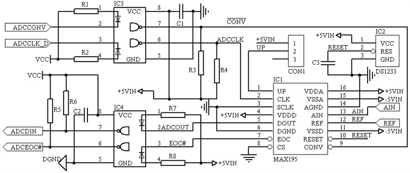
Fig. 2External circuit design chart of MAX195

The signal from gauge head is first converted to 0-5 V voltage signal after magnified and filtered. Then the analog signal is transformed into data signal from 3 MAX195 A/D chips as shown in Fig. 2. The MAX195 chips used can transform analog signal into serial binary code with its inner successive approximation register. The chips are 16 bits converter which resolution ratio can reach 0.0625 mV when the unipolar input analog signal is between 0-4 V and can meet precision demands. The pin 1 is input by tristate signal as BP/UP/SHEN. When the pin is free, the input signal that is transformed is bipolar and between –REF-REF, where REF is reference value of the chip’s voltage and its max value is 5 V. When the pin is high level, the input signal is unipolar and between 0-REF. When the pin is low level, the input is closed and there only exists 10 μA holding current. Also in Fig. 2, CS means chip selection, when it is low level, there has serial signals output, so it is grounded in the system. The signal DOUT and EOC are connected to FPGA through photocoupler, where DOUT is serial output and EOC is conversion output end signal of MAX195 chip. The EOC signal is valid only at low level. It is turned into high in one clock cycle since conversion begins, and it is turned into low in one clock cycle since conversion ends. The FPGA decides with the EOC’s state when to read serial data.
To get precise position of each axis, the orthogonal raster signal should be filtered, subdivided, counted reversibly and its direction should be distinguished with the FPGA. All the functions are simulated in Fig. 3. The principle of data filtering is to eliminate burr and noise of the input square wave through clock delay, and how many clock cycles should be delayed is decided by pulse width of the burr and noise, in Fig. 3 it is 10 ns as shown in a) and b). A and B is orthogonal raster signal in Fig. 3, when the raster moves forward, their states are 00→10→11→01→00, and the invertible counter plus 1 with state changing each time. When the raster moves reversion, their states are 00→01→1l→10→00, and the invertible counter minus 1 with state changing each time. Dab is signal after 4 subdivided and Dout is signal output.
Fig. 3Simulation of 4 subdivision, direction distinguish and reversible counter

a)

b)
3.2. Key technique of data acquisition
3.2.1. Synchronous data acquisition
According to the point data format (px+x, py+y, pz+z, θ), the 7 path signal should be gathered synchronously to get more precision point coordinates. To do so, a synchronous latching signal is set to lock the 7 path data simultaneously in FPGA. But it takes time to turn analog signals to digital ones, if the 7 path data is latched at the very beginning of A/D conversion, then the gauge head data latched may be A/D transforming value last time, and the raster data may be the data when latched signal triggered. Thus there exists a certain error between data from gauge head and raster, which is called synchronous error. If the time interval between two A/D conversion is t, and the measuring velocity is v, the max synchronous error may be vt in one latching process. If the time interval between two A/D conversion is short enough to reduce the error thoroughly, the data from gauge head and raster can be considered as synchronous data. For example, the time interval between two A/D conversion of MAX195 is 10 μs in the system, the measuring velocity is 20 mm/s, so the max synchronous error is only 0.2 μm.
3.2.2. Equal interval data acquisition
Data is collected with the same gathering rate in common data acquisition card, which in fact is equal time interval. Yet the velocity of motor is varied when measuring, the space curve described by points data from equal time interval gathering is unreasonable. The points should be gathered uniformly-spaced to get a more accurate measured object’s outline. To gather uniformly-spaced data, raster data of an axis is set for reference (assumed to be Y), then space of data gathering is set to l. The process to obtain a series of uniformly-spaced points is shown as follow, first we got many points such as:
In above points, D1 is the first measuring point, DN is the last measuring point. Di stands for each measuring point except first one, where i= 2, 3,…, N. For each point’s reference value yi, if (yi-y1)≥(j-1)l, a new point is obtained as D'j, where j=2, 3,…, M. Then a series of uniformly-spaced points are obtained as follow:
There also exists error in the process, to judge the precision of the uniformly-spaced measurement, the variance of uniformly-spaced is calculated as Eq. (1):
where, stands for actual sample space, and is the mean value of it.
3.2.3. High-speed data acquisition
There are two ways to produce latched signal, one is sent by upper computer and the other is triggered by FPGA at certain time interval. The latter one is better than the former one because the picking rate is seriously restricted by the signal sending rate of upper computer in the fomer way. To produce latched signal by FPGA, a counter should be set to count the clock signal, and latched data is produced when the counting value equals the counter’s initial value. When the 7 path latched signal is produced, it will then be stored in the FIFO. The initial value of the counter can be decided by real demand. If the max measuring rate is , the sampling interval is l, then the sampling frequency must be greater than To obtain enough sampling points with uniformly-spaced, the sampling frequency of the system is set to 10, if the clock frequency of FPGA is , then the initial value of the counter should be .
3.3. Data storage and retrieval
IDT7208 is used as FIFO in the system, which has a volume of 64K×9. In the measuring process, the latched data of points measured from FPGA is stored into FIFO through bus line to avoid data losing when the upper computer can’t read data timely. When the data stored in FIFO achieves a certain amount, an interrupt request triggered by FPGA is sent to upper computer for it to read data from FIFO orderly. For the read and write functions of FIFO, the new data can still be stored when the old ones are read by upper computer, thus the data can be acquired continuously.
4. Experimental result and analysis
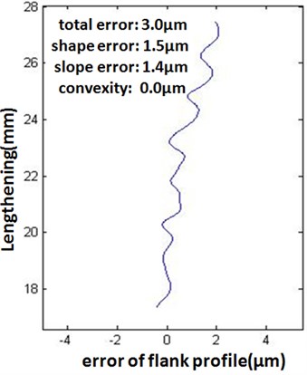
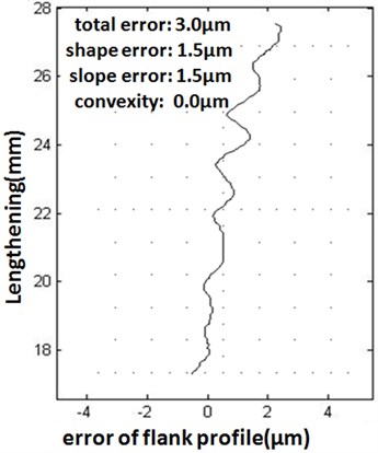
A cylindrical gear’s flank profile is measured with the CNC gear measurement center of our design, a section of the tooth profile error curve is shown in Fig. 4(a). In the measuring process, the sampling frequency is set to 10 kHz, the measuring rate 20 mm/s, the sampling interval 20 μm and axis acts as interval reference axis. Then the same section curve is measured with another measurement center with measuring rate 10.2 mm/s which it can achieves, the other measuring parameters are the same, the result is shown in Fig. 4(b). By contrast of the result, it can be seen that the designed center can ensure survey precise even when the measuring speed increases one times. So the measurement center of our design can meet the demands of measuring gear with higher speed.
From the data measured by the CNC gear measurement center designed, the real sampling interval , is calculated and a series of actual sampling interval value is obtained. Then the mean value of the real sampling interval is calculated as μm, so square deviation is counted by above formula (1) as 0.72 μm. It can be seen that there is a fairly good uniformly-spaced from the result.
Fig. 4Contrast of experimental result

a) measuring result of our design

b) measuring result of another type
5. Conclusion
To collect multi-channel data synchronously with high speed for CNC gear measurement center, a data acquisition system with FPGA as core chip instead of single chip or DSP is designed. The system can not only collect data with uniformly-spaced and high speed synchronously, but also can work under different rate and sampling interval. It can meet the demands of measuring diverse gear.
Comparison experiments shows that the CNC gear measurement center designed can achieve 10 kHz sampling frequency when gathering 7 path data synchronously and the equal interval error is below l μm, when the measuring speed is set to 20 mm/s and sampling interval to 20 μm.
References
-
Mao Zhen-Hua, Ding Li-Hua, et al. Design and simulation of gear measurement center AC servo control system. Instrument Technique and Sensor, Vol. 6, 2012, p. 42-45.
-
Wang Jing-Kun Electrical system design of gear measurement center. Mechanical Engineer, Vol. 6, 2008, p. 76-77.
-
Zhang Lei Measurement of rack hob based on CNC gear measuring center. Aeronautical Manufacturing Technology, Vol. 14, 2011, p. 62-65.
-
Gao Shan-Ming, Gao Zhi-Yu Designed on full-closed loop control system of gear measuring centre. Mechanical Engineer, Vol. 1, 2012, p. 83-85.
-
Shen Tao, et al. Processing circuit design of three-dimensional probe for cnc gear measuring center. Value Engineering, Vol. 27, 2012, p. 17-19.
-
Yang Hui-Zhe, Lao Qi-Cheng The design of servo system for CNC gear measuring center. New Technology, Vol. 3, 2011, p. 50-52.
-
Yang Lin-Nan, et al. Design of high speed multichannel data gathering system based on FPGA. Computer Engineering, Vol. 33, Issue 7, 2007, p. 246-248.
-
Liu Zhao-Hua, Dai Yi, et al. Research on multichannel synchronization data acquisition system based on PC/104 bus and FPGA. Mechanical and Electronic, Vol. 1, 2011, p. 39-43.
-
Liu Chun-Ya, Cheng Xu, et al. Design and realization of data acquisition system based on FPGA. Electronic Design Engineering, Vol. 19, Issue 1, 2011, p. 51-54.
-
Yu Zhi-Heng, Ye Jun-Ming, et al. A design of high speed and deep asynchronous FIFO based on FPGA and DDR2 SDRAM. Microcomputer and Application, Vol. 30, Issue 4, 2011, p. 34-36.
-
Lian Peng-Bo, Wang Xue-Wu, et al. The hardware design of XDAS based on FPGA and USB2.0. Manufacturing Automation, Vol. 34, Issue 9, 2012, p. 5-6.
-
Deepa P., Vasanthanayaki C. FPGA based efficient on-chip memory for image processing algorithms. Microelectronics Journal, Vol. 43, Issue 11, 2012, p. 916-928.
