Abstract
In order to study the vibration characteristics of the workpiece spindle of a gear hobbing machine, this paper established a mathematical model for the workpiece spindle vibration displacement in the -axis direction. To verify the reliability of the proposed model, a series of experiments were run on the CNC gear hobbing machine. The relative error between the experimental data and the calculated values was lower than 5 %, which proves that our proposed mathematical model is qualified to be a research tool for the investigation of the variation law of the workpiece spindle. According to the analysis results, the workpiece spindle vibration displacement literally decreases with the increasing order, and the hobbing process with high hob revolution speed and small cutting depth is preferable for gear hobbing accuracy.
Highlights
- A model for the vibration displacement of workpiece spindle was developed.
- The variation law of the workpiece spindle was investigated.
- The vibration displacement of worktable spindle decreases with increasing order.
- The higher hob revolution speed and smaller cutting depth is preferable.
1. Introduction
The high-speed cutting hobbing machine tool is a kind of specialized CNC (computerized numerical control) machine tool for gear processing. With the booming of the auto industry, there are more requirements for gear hobbing accuracy [1-7]. In the processing of high-speed-heavy-duty gear hobbing, there are many vibration sources. These include the servo motor(s), guide screw, hydraulic cylinders and hobbing vibration. The hobbing vibration, as the biggest effect factor, affects the gear processing quality in three ways, i.e., deviation of meshing point between hob and workpiece, additional dynamic load to hob causing the acceleration of cutting tool wear and vibration marks on the gear surface [8-10]. Therefore, study on the spindle vibration characteristics is meaningful to improve the processing quality and prolong the hob life for gear hobbing machine tools.
In order to analyze the stiffness characteristics and harmonic responses of columns of a large-scale NC gear hobbing machines, Yang et al. conducted a finite element simulation to quantify the harmonic responses of the columns. According to the analysis results, instructive geometric parameters for the optimization design of columns were given [11]. Except for this study, there are rare studies of the hobbing vibration issue in the literature. However, vibration analysis models for other kind of machines tools have been widely reported in the literature [12-14]. Wan and Yang proposed a vibrating monitoring system to instantaneously measure the vibration of a numerical control spindle. Test results showed that proposed vibration monitoring system not only can characterize the time domain wave and the spectrum distribution, but also can implement the tracing of the time-frequency distribution [15]. Considering that previous related researches manly focus on the first-order frequency vibration of the ultra-precision diamond machining machine, Chen et al. studied the multi-order frequency vibration and its influences on the surface generation in fly-cutting. Following experimental results proved the analysis results [16]. Since the vibration modal is a function of frequency, instead of directly measuring vibration, Wu et al. and Chen et al. separately measured and analyzed the cutting force signals to study the cutting vibration characteristics of machine tools [17, 18]. Since both the dynamic and static characteristics of the cutters have a strong influence on the processing accuracy, some scholars made a lot of efforts at the stage of design and manufacture of the cutters [19-21]. Since the vibration issue is not only related to the dynamic characteristics of the cutter, but also other components of machine tools, to reduce the adverse effect resulting from the vibration of machine tools, some advices for the structure optimizations of entire machine tools were proposed [22-28].
Note that for the gear hobbing machine tools, none of these research methods mentioned above can directly obtain the value of workpiece spindle vibration displacement and the vibration rule of the workpiece spindle is still not clear. Hence, this paper aims to study the vibration of the workpiece spindle and quantify the displacement of the workpiece spindle due to the vibration. On this basis, the vibration rule of the workpiece spindle of the gear hobbing machine can be uncovered.
2. Establishment of vibration displacement theoretical model of workpiece spindle
For a hobbing machine, the vibration displacement in the or -axis direction has less impact on the processing accuracy than that in the -axis direction, hence only the vibration characteristics of workpiece spindle in the -axis direction was studied. As shown in Fig. 1, the workpiece spindle of a hobbing machine consists of the fixture and the workpiece to be cut. The fixture, which is vertically bolted on the worktable, rotates together with the worktable during the processing.
Fig. 1The diagram for the hobbing zone and workpiece spindle of gear hobbing machine
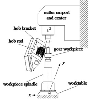
a) The hobbing zone
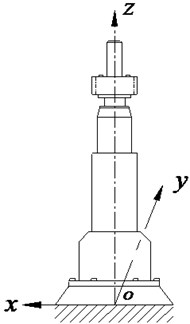
b) The workpiece spindle regarded as cantilever beam
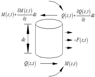
Since entire gear hobbing system is very complicated, some structural simplification was done in the modeling, in which the workpiece spindle was treated as an Euler-Bemoulli beam, as sketched in Fig. 2. Assuming that:
• The central axis of every cross sections are in the same plane (plane ).
• Every micro-segment of the beam only suffers bending vibration.
• The effects of the moment of inertia and shear deformation are negligible.
• The rotation of the cross section around the central axis is negligible.
According to the theory of the cantilever beam [29], the movement of the workpiece spindle in the -axis direction can be formulated by:
where, denotes the density of the workpiece spindle, is the cross section area of the workpiece spindle, represents the transverse displacement of the workpiece spindle (which are the function of cross section position and time), is the shear force, and is the cutting force in the -axis direction (derived from the process parameters).
By ignoring the effect of cross sectional rotation of spindle, the rotational equation of the micro segment is:
where, is the bending moment of cross section. Due to the value of second-derivative of is small, Eq. (2) can be simplified as:
By substituting Eq. (3) into Eq. (1), the movement of workpiece spindle in the -axis direction can be re-defined as:
The dynamic equation of workpiece spindle on the whole interval should be subject to Eq. (4). According to the theory of material mechanics [30], the relationship between the beam deformation and the bending moment can be formulated as:
where, denotes elastic modulus of workpiece spindle, is the inertia moment of cross section normal to the centroid axis (). represents the diameter of spindle, , are the height of workpiece spindle and the density of workpiece spindle respectively, and is the cross section area of workpiece spindle. Since the relative position among the workpiece, fixture and worktable is very stable, the workpiece and fixture were treated as a single axis in the modeling. Besides, due to the good hardness and high strength of both workpiece and fixture, the cutting force was loaded at the center line of the spindle.
Fig. 2The diagram for the analysis model of the Euler-Bemoulli beam representing workpiece spindle
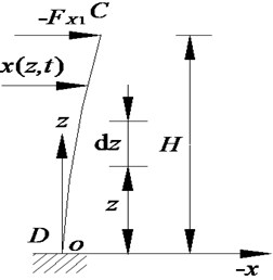
a)
b)
Since the workpiece spindle was considered as a uniform cross section beam, was regarded as a constant, by substituting Eq. (5) into Eq. (4):
By setting 0, the differential equation representing the free vibration of workpiece spindle is:
where, can be further divided into:
By substituting Eq. (8) into Eq. (7):
where, is the natural frequency of workpiece spindle vibration system. By simplifying Eq. (9), we can get:
By solving Eqs. (10)-(12), following equation can be obtained:
According to Eq. (13), the general solution to the bending vibration of uniform cross sectional cantilever beam is:
The boundary condition of the cantilever beam were set as: 0, 0, 0, 0, then, substituting these boundary conditions into Eq. (14):
By rearranging Eq. (15):
where, condition of nontrivial solution of is that the determinant of the matrix above is zero, hence:
By rearranging Eq. (17), the characteristic equation would be:
By solving Eq. (18), characteristic root of the transverse vibration of the workpiece spindle was shown in Table 1.
Table 1The characteristic root for the transverse vibration of the cantilever beam of workpiece spindle
1.875 | 4.694 | 7.855 | 10.996 |
– | |||
14.137 | 17.278 | 20.419 | – |
According to Table 1, the characteristic roots of the transverse vibration can be approximated as:
By substituting Eq. (19) into Eq. (12), the natural frequency of the workpiece spindle would be:
After the characteristic roots for the workpiece spindle vibration was defined, the ratio of to can be calculated by:
Hence, the mode function representing the natural frequency of workpiece spindle can be formulated as:
By substituting Eqs. (14), (19) and (22)) into Eq. (8), the general solution to the homogeneous uniform-cross-section beam is:
According to the initial boundary conditions of and , the Eq. (23) can be further simplified as:
Due to the orthogonal characteristic of the trigonometric function, we can get:
Hence:
Assuming that the cutting force is exerted on the top of the workpiece spindle [31], when 0, the initial vibration displacement would be:
The initial velocity of vibration is:
Combing Eqs. (24)-(30), we can get:
By solving Eq. (31):
Substituting Eqs. (19), (20), (22) and (32) into Eq. (23), the vibration response of the workpiece spindle would be:
Since the workpiece is installed at the top of the workpiece spindle during the hobbing process. continuous cutting force should be imposed on the workpiece spindle at the position of . By substituting and into Eq. (33), the vibration displacement of workpiece spindle in the -axis diretion can be defined as:
where, is the normal modulus of hob, represents the revolution speed of hob, is the endurance of hob, is cut depth of hob, is the number of gear teeth, , , are the correction coefficients for the workpiece material, the workpiece hardness and the helical angle respectively. Their values are listed in Tables 2 and 3. With the help of Eq. (34), the corresponding displacements due to first, second and third orders of vibrations of the workpiece spindle can be calculated respectively.
Table 2The parameter of hob spindle and gear hobbing process
Parameter | / mm | (r/min) | / min | / mm |
Value | 3 | 636.94 | 960 | 6.75 |
Parameter | ||||
Value | 1 | 1.15 | 1.08 | 42 |
Parameter | / GPa | / kg.m3 | / mm | / mm |
Value | 160 | 7320 | 120 | 700 |
Parameter | / Poisson ratio | Revolution speed of hob spindle (r/min) | ||
Value | 0.25 | 45.5 (1-200 r/min) | ||
Table 3The hob spindle parameter
Parameter | / GPa | / kg.m3 | / mm | / mm |
Value | 206 | 8400 | 80 | 200 |
Parameter | / Poisson ratio | Revolution speed of hob spindle (r/min) | ||
Value | 0.25 | 636.94 r/min (100-1500 r/min) | ||
3. Measuring and analyzing the vibration displacement of the worktable assembly
3.1. Experimental setup
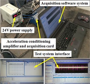
To verify our proposed mathematical model mentioned above, a series of experiments were conducted by using the DH311E-type accelerometer. The accelerometer was used to measure the vibration acceleration of the workpiece spindle in the -axis direction. The sensibility of selected accelerometer reaches to 1.01 mv/m.s-2, and corresponding frequency ranges from 1-5000 Hz. The magnetic gauge head of this accelerometer was horizontally fixed to the non-rotating shell of workpiece spindle. Fig. 3 shows the location of gauge head. The developed workpiece spindle vibration acceleration measuring system consists of a amplifier with 12 channels, a 16 bit synchronization data acquisition board (NI PXIe-6356), a 24 VDC power supply, a accelerometer and a self-developed signal analysis software. This software system was developed based on the LABVIEW. After acquiring the value of vibration acceleration, the value of the vibration displacement can be automatically calculated by using the combination of the fast Fourier transform algorithm and the similarity transformation, workpiece spindle workpiece spindle. Fig. 4 shows the data analysis software developed in the upper monitor.
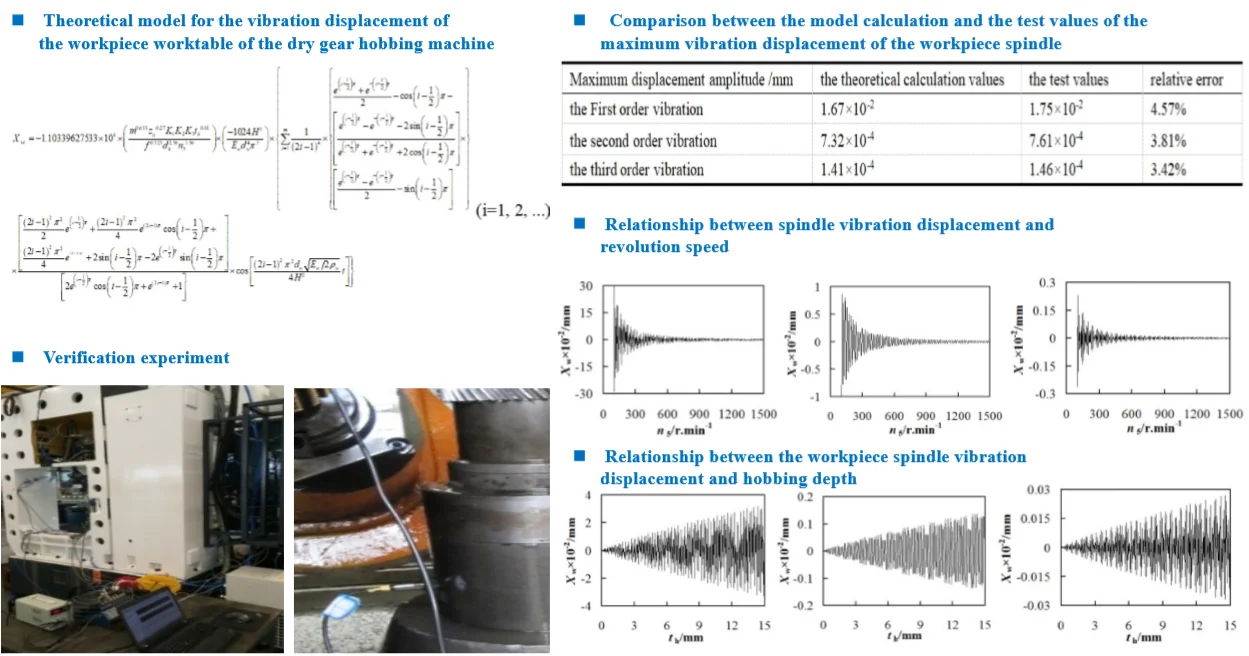
During the experiments, the cut depth and the revolution speed of hob were fixed at 6.75 mm and 636.94 r/min respectively, the output data from the self-developed software was shown in Fig. 5. Fig. 5 shows that no matter at what vibration order, the vibration displacement of workpiece spindle varies with time periodically. The maximum displacement of the first order vibration is 1.75×10⁻²mm, whereas those of second- and third- order vibrations are 7.61×10⁻⁴mm and 1.46×10⁻⁴mm respectively. On the other hand, by solving Eq. (34) mentioned above, the theoretically maximum values of vibration displacements at different orders were calculated. The comparison between the calculated results and experimental data are shown in Table 4. Their relative deviation is less than 5 %, which suggest a good agreement between theoretical prediction and experimental data. It validated the rightness of the developed theoretical model for the vibration displacement of the workpiece spindle.
Fig. 3Experimental setup and location of gauge head
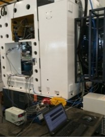
a) Experimental setup
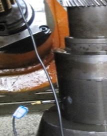
b) Location of gauge head
Fig. 4The diagram for vibration test system and interface of gear hobbing machine
3.2. The analysis of the effect of vibration displacement on the processing accuracy
Theoretically, there are three factors affecting the quantity of vibration displacement: vibration order, revolution speed of hob and cut depth. By running our developed model mentioned above, they were carefully studied here.
3.2.1. Variation in the displacement due to the change in vibration order
According to theoretical analysis results shown in Table 4, when the cut depth and revolution speed of hob were fixed at 6.75 mm and 636.94 r/min respectively, the calculated maximum displacement of the first order vibration was 1.67×10⁻²mm, whereas those of second and third order vibrations were 7.32×10⁻⁴mm and 1.41×10⁻⁴mm respectively. The first-order vibration causes the largest displacement to the workpiece spindle, which could leave marks on the surface of finished gear. Comparatively, the displacements due to second and third- order vibrations can be ignored, because their values are smaller than the allowed feeding accuracy (i.e., 0.001 mm) in the -axis direction under such a machining condition.
Fig. 5The curve of relationship between workpiece spindle vibration displacement and time
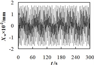
a) The first order
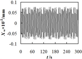
b) The second order
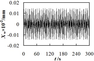
c) The third order
Table 4Comparison between the theoretical model calculation and the test values of the maximum vibration displacement of the workpiece spindle
Maximum displacement amplitude /mm | The theoretical calculation values | The test values | Relative error |
The First order vibration | 1.67×10⁻² | 1.75×10⁻² | 4.57 % |
The second order vibration | 7.32×10⁻⁴ | 7.61×10⁻⁴ | 3.81 % |
The third order vibration | 1.41×10⁻⁴ | 1.46×10⁻⁴ | 3.42 % |
3.2.2. Variation in the displacement due to the change in hob revolution speed
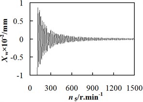
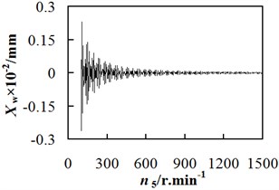
Fig. 6 illustrates the relationship between the vibration displacement of workpiece spindle and the revolution speed of hob spindle. When cut depth is fixed at 6.75 mm, the vibration displacement of workpiece spindle is relatively large in the condition of low revolution speed; with the increasing revolution speed and vibration order, the amount of vibration displacement fluctuates periodically and gradually decreases. When 6.75 mm, 100 r/min, the firstorder vibration amplitude was 3.13×10⁻¹ mm, whereas the those of second and third order vibrations were 8.46×10⁻³ mm and 2.31×10⁻³ mm respectively. Therefore, a conclusion can be dropped that for a gear hobbing machine with high rigidity, the high-speed hobbing process has a better processing accuracy than its counterpart. Besides, the adverse effect of vibration displacement on the processing accuracy is clearer at the initial processing stage.
3.2.3. Variation in the displacement due to the change in cutting depth
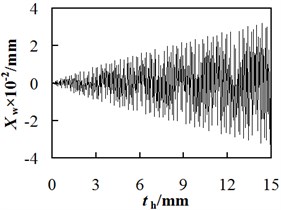
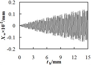
The relationship between the vibration displacement of workpiece spindle and the cut depth was shown in Fig. 7, in which the revolution speed of hob is fixed at 636.94 r/min. The vibration displacement increases with the cut depth but decreases with the vibration order, and the vibration amplitude is large. According to Fig. 7, when the cut depth is too large, the chatter occurs, leading to an obvious adverse effect on the gear hobbing accuracy. Therefore, adopting the multi-cut method (Adjust the cutting depth multiple times to process a single workpiece) can effectively alleviate the effect of vibration displacement of workpiece spindle on the position deviation of cutting point.
When 15 mm, 636.94 r/min, the maximum value of the first order vibration displacement is approximately 3.29×10⁻² mm, those of the second and third order vibration displacements are 1.36×10⁻³ mm and 2.69×10⁻⁴ mm respectively. Hence, a conclusion can be made that compared to the hobbing process with a single cut but full cut depth, that with multi-cuts but small cut depth at each time can achieve a smaller vibration displacement, and hence a smaller position deviation of the cutting point.
Fig. 6Relationship between workpiece spindle vibration displacement and revolution speed
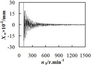
a) The first order
b) The second order
c) The third order
Fig. 7The relationship between the workpiece spindle vibration displacement and hobbing depth
a) The first order
b) The second order
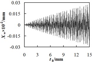
c) The third order
According to the analysis above, at the initial stage of gear hobbing, there could be a serious vibration chatter. However, when the cut depth remains unchanged, with the increasing revolution speed of hob, the vibration displacement of workpiece spindle gradually decreases and then level off. On the other hand, when the hob revolution speed keeps constant, the displacement of workpiece spindle sharply increases with the increasing cut depth. Therefore, to alleviate vibration and improve the dynamic performance of the gear hobbing machine, the workpiece should be processed with a relatively high revolution speed and small cut depth (i.e., adopting multi-cut method). In this way, the phenomenon of vibration marks can be alleviated and accordingly the quality and efficiency of gear hobbing process can be improved.
4. Conclusions
According to the principle of vibration dynamics as well as the Euler-Bernoulli beam theory, the theoretical model of vibration displacement of workpiece spindle of gear hobbing machine was deduced, which can directly predict the amount of displacements based on the spindle structure and process parameters. With the help of the developed model, the major effect factors influencing the amount of vibration displacement were carefully studied, and following conclusion can be made:
1) The deviation between theoretical prediction and experimental data is less than 5 %, which indicated that the developed mathematical model was qualified to investigate the vibration displacement of workpiece spindle.
2) When the cut depth and revolution speed of workpiece spindle were fixed at 6.75 mm and 100 r/min respectively, the maximum first order vibration displacement reached to 3.13×10⁻¹ mm, which could cause a deviation of the meshing point between hob and workpiece. In that case, the tooth alignment error, tangential error and helical error would appear. As a result, the vibration marks generate on the gear surface.
3) To alleviate the processing error caused by vibration and improve the gear hobbing accuracy, the hobbing process with relatively high revolution speed of hob and small cut depth should be adopted.
References
-
Abele E., Altintas Y., Brecher C. Machine tool spindle units. CIRP Annals-Manufacturing Technology, Vol. 59, Issue 2, 2010, p. 1-22.
-
Jiang S., Zheng S. Dynamic design of a high-speed motorized spindle-bearing system. Journal of Mechanical Design, Vol. 132, Issue 3, 2010, p. 345011-345015.
-
SarinaZhang S., Liu X. Identification of accuracy characteristics importance of machine tool for parts machine ability evaluation. Journal of Mechanical Engineering, Vol. 49, Issue 9, 2013, p. 113-120.
-
Liu H., Huang Y., Zhang H., Zhao W. Effects of transmission stiffness variations on the dynamic accuracy consistency of CNC feed drive systems. Journal of Mechanical Engineering, Vol. 50, Issue 23, 2014, p. 128-133.
-
Zhao W., Zhang J., Liu H., Yang X. New evaluation method on the precision of NC machine tools. Engineering Science, Vol. 15, Issue 1, 2013, p. 93-98.
-
Majda P. Modeling of geometric errors of linear guideway and their influence on joint kinematic error in machine tools. Precision Engineering, Vol. 36, Issue 3, 2012, p. 369-378.
-
Pang J., Zhang G., Zhou H., Li F., Li P., Fu P. Study on reverse mapping of accuracy design quality characteristics for numerical machine based on rough set. Journal of Mechanical Engineering, Vol. 48, Issue 5, 2012, p. 101-107.
-
Rao B., Shin Y. A comprehensive dynamic cutting force model for chatter prediction in turning. International Journal for Machine Tools and Manufacture, Vol. 39, Issue 10, 1999, p. 1631-1654.
-
Altintas Y. Manufacturing Automation: Metal Cutting Mechanics, Machine tool Vibrations and CNC Design. Cambridge University Press, Cambridge, 2000.
-
Ertürk A., Ӧzgüven H. N., Budak E. Analytical modeling of spindle-tool dynamics on machine tools using Timoshenko beam model and receptance coupling for the prediction of tool point FRF. International Journal of Machine Tools and Manufacture, Vol. 46, Issue 15, 2006, p. 1901-1912.
-
Yang Y., Wang S., Tian Z., Zhou J., Kang L. Dynamics simulation analysis of column for large-scale NC gear hobbing machine. China Mechanical Engineering, Vol. 24, Issue 11, 2013, p. 1473-1479.
-
Zverv I., Pyoun Y. S., Lee K. B., Kim J. D., Jo I., Combs A. An elastic deformation model of high speed spindles built into ball bearings. Journal of Materials Processing Technology, Vol. 170, Issue 3, 2005, p. 570-578.
-
Sun M., Liang M., Gan J., Yin G. An optimum identification method of dynamic characteristic parameters of guideway joint on a NC machine tool. Journal of Sichuan University, Vol. 44, Issue 3, 2012, p. 217-223.
-
Li X., Yang Y. Abrasion properties of composite sliding guide ways for gear hobbing machine. China Mechanical Engineering, Vol. 27, Issue 9, 2016, p. 1176-1183.
-
Wan H., Yang S. Development of HHT-based vibration monitoring system for NC spindle. Journal of Vibration and Shock, Vol. 33, Issue 6, 2014, p. 48-52.
-
Chen W., Lu L., Yang K., Su H., Chen G. An experimental and theoretical investigation into multimode machine tool vibration with surface generation in flycutting. Journal of Engineering Manufacture, Vol. 230, Issue 2, 2016, p. 381-386.
-
Wu W., Liu Q. Extended transfer matrix method for dynamic modeling of machine tools. Journal of Mechanical Engineering, Vol. 46, Issue 21, 2010, p. 69-75.
-
Chen X., Zhang P., Liu J., He Y. Multi-physical coupled dynamic characteristics of high-speed motorized spindles. Journal of Vibration Engineering, Vol. 26, Issue 3, 2013, p. 303-310.
-
Dimla Sr D. E., Lister P. M. On-line metal cutting tool condition monitoring I: force and vibration analysis. International Journal of Machine Tools and Manufacture, Vol. 40, Issue 5, 2000, p. 739-768.
-
Li H., Li X. Modelling and simulation of chatter in milling using a predictive force model. International Journal of Machine Tools and Manufacture, Vol. 40, Issue 14, 2000, p. 2047-2071.
-
Merrit H. E. Theory of self-excited machine tool chatter. Transactions ASME – Journal of Engineering for Industry, Vol. 87, Issue 4, 1965, p. 447-454.
-
Sun M., Yin G., Hu T. Orthogonal optimization method of dynamic stiffness of machine tool joints based on modal flexibility. Journal of Sichuan University (Engineering Science Edition), Vol. 45, Issue 4, 2013, p. 90-96.
-
Rehorn A., Jiang J., Orban P. E., Bordatchev E. Modelling and experimental investigation of spindle and cutter dynamics for a high-precision machining center. International Journal of Advanced Manufacturing Technology, Vol. 24, Issues 11-12, 2004, p. 806-815.
-
Smith S., Jacobs T. P., Halley J. The effect of drawbar force on metal removal rate in milling. CIRP Annals- Manufacturing Technology, Vol. 48, Issue 1, 1999, p. 293-296.
-
Schmitz T. L., Davies M. A., Medicus K., Snyder J. Improving high-speed machining material removal rates by rapid dynamic analysis. CIRP Annals- Manufacturing Technology, Vol. 50, 2001, p. 263-268.
-
Lin S., Chang M. A study on the effects of vibrations on the surface finish using a surface topography simulation model for turning. International Journal of Machine Tools and Manufacture, Vol. 38, Issue 7, 1998, p. 763-782.
-
Yang Z., Yin G., Shang X., Jiang H., Zhong K. Coupling analysis model of thermal and dynamic characteristics for high-speed motorized spindle. Journal of Jilin University (Engineering Technology Edition), Vol. 41, Issue 1, 2011, p. 100-105.
-
Yang Y., Liu Q., Shen J., Tian K. Machine tool structure design based on the coupling analysis of dynamics and cutting performances. Journal of Vibration and Shock, Vol. 32, Issue 10, 2013, p. 198-202.
-
Zhang Y. Mechanical Vibration. Tsinghua University Press, Beijing, 2007.
-
Liu H. Material Mechanics. Higher Education Press, Beijing, 1991.
-
Wang S., Yang Y., Zhou J., Li Q., Yang S., Kang L. Effect of machining precision caused by NC gear hobbing deformation. Advances in Power Transmission Science and Technology, Vol. 86, 2011, p. 225-232.
About this article
This study is supported by Chongqing Outstanding Youth Scholar Special Foundation (cstc2014jcyjjq70001), Key Program of National Natural Foundation of China (51635003), China Postdoctoral Science Special Foundation (2017M612920), Chonqing Postdoctoral Science special Foundation (Xm2017044, Xm2017110). Chongqing Scientific and Technological Innovation Leader Project.
Yong Yang developed the theoretical model for spindle vibration. Xiangguang Li conducted a series of experiments to provide experimental data to verify proposed model. Zheng Zou was in charge of the paper writing, experimentation design and data analysis. Lingwan Zeng developed an interface on the computer to read the real-time experimental data. Li Wang collected the experimental data, she was also involved in the data analysis.
