Abstract
This study investigates an approach for parametric modeling and dynamic contact analysis of involute/noninvolute beveloid gears. Firstly, the mathematical models of involute/noninvolute beveloid gear pairs are derived based on the theory of gearing and the generation mechanism. Then the parametric modeling programs of involute/noninvolute beveloid gears are developed to automatically generate exact model via a Matlab code. Subsequently, a numerical example of intersecting axes beveloid gears is presented to evaluate the dynamic stress distribution and dynamic transmission error. Finally, the dynamic contact characteristics of involute and noninvolute beveloid gears are calculated by three-dimensional dynamic contact finite element method, respectively. The results show that the noninvolute beveloid gear pairs can relieve the high dynamic stress and contact shock problem of intersecting axes beveloid gear pairs.
1. Introduction
In modern gearing application, spiral bevel gears, hypoid gears, worm gears and face gears can easily realize the non-parallel axes power transmission, and they represent good meshing characteristic at large shaft angles, close to 90°. However, it is not practical to use them when the shaft angle is less than 45°, due to design and manufacturing difficulties. Beveloid gears, by contrast, also known as conical gears with perfect meshing characteristics, are suitable for power transmission not only between parallel axes but between non-parallel axes [1, 2].
Recently, a number of studies have been performed on the beveloid gears. Brauer derived the parametric equations for a straight conical involute gear tooth surface [3], and these formulas were used to create a finite element model [4], then reported on a theoretical study of transmission errors in involute conical gear transmissions [5]. Liu, Ye and Chen established the mathematical models of variable thickness involute gears and the contact characteristic was also studied [6-8]. Chen solved the tooth face equations of helical involute beveloid gear, and the precise tooth surface was generated utilizing Matlab [9]. Wu proposed an approach for geometrical design and contact stress analysis of skew conical involute gear drives in approximate line contact [10]. Li investigated the tooth profile equation of noninvolute beveloid gears and also calculated the tooth profile errors and axial errors [11]. In spite of the above-mentioned studies focusing on meshing theory and simulation of involute or noninvolute beveloid gears, there are very few published works aimed to solve the engagement equation and tooth profile equation of noninvolute beveloid gears between intersecting axes by means of tooth face equation of the imaginary helical rack cutter. Furthermore, none also made a comparison between dynamic contact characteristics of involute beveloid gear pair and noninvolute beveloid gear pair. These gaps will be the emphasis of this paper.
2. Mathematical model of the involute beveloid gear pair
2.1. Transverse tooth profile equation of helical rack cutter
Considering the meshing relationship between imaginary rack cutter and gear blank, we can obtain the tooth profile equation of involute beveloid gear basing on the tooth profile equation of the rack cutter in transverse cross section. Therefore, the parameters of rack cutter in the transverse cross section should be calculated first.
The relative position relationship between rack cutter and gear blank is shown in Fig. 1. Here, r' means gear pitch radius, r'ω is linear velocity of gear and the pitch plane of imaginary rack cutter is set to form an inclination angle δ with respect to the pitch plane of gear.
Fig. 1Relative position relationship
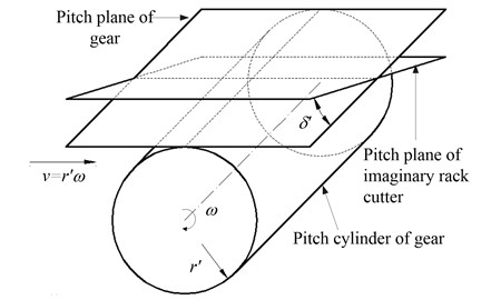
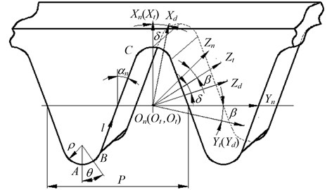
Fig. 2 describes the geometry of normal tooth profile of rack cutter. Sn(Xn,Yn,Zn) means fixed coordinate system linked with normal cross section of rack cutter. The geometry of normal tooth profile of rack cutter, which mainly contains straight edge BC and tool fillet curve AB, is represented. The BC and AB generate the working tooth surface and fillet surfaces of involute beveloid gear, respectively.
Fig. 2Normal tooth profile of rack cutter
The equation of BC in coordinate system Sn can be described as:
where Rzn is position vector of arbitrary point on BC in coordinate system Sn; αn is the normal pressure angle; mn is normal module; h*an represents the addendum coefficient; l is the distance between moving point on BC and point B; the upper and lower signs of “±” are used to describe the left and right straight edge of rack cutter.
The equation of AB in coordinate system Sn can be described as:
where Rjn is position vector of arbitrary point on AB in coordinate system Sn; θ denotes the central angle between moving point on AB and point A; ρ represents the radius of fillet.
Using the coordinate transformation from Sn(Xn,Yn,Zn) to St(Xt,Yt,Zt) which obtains from rotating Sn(Xn,Yn,Zn) around the Xn axis with an angle β, the coordinate system Sd(Xd,Yd,Zd) will be got though rotating St around the Yt axis with an angle δ, and they are illustrated in Fig. 2. Combining Eqs. (1) and (2), we can gain the rack cutter equations of straight edge BC and tool fillet curve AB in the XtOtZt plane of St as follows:
Then the rack cutter equations of straight edge BC and tool fillet curve AB in the XdOdZd plane of coordinate system Sd are as follows:
2.2. Coordinate transformation of rack cutter
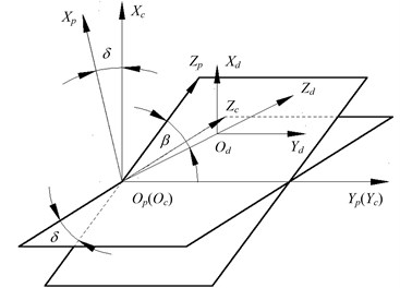
Fig. 3 displays the coordinate systems of rack cutter. Herein, the coordinate system Sd moving a given translational distance u along negative direction of Zd axis and rotating it around the Xd axis with an angle β, the coordinate system Sc(Xc,Yc,Zc) will be got by rotating Sp around the Yp axis with δ.
Fig. 3Coordinate systems of rack cutter
In the coordinate system Sc, the tooth surface equation of rack cutter can be expressed as:
where Rc and Rd are position vector of rack cutter in coordinate system Sc and Sd, respectively; Mpd and Mcp are coordinate transformation matrix.
Combining Eqs. (4) and (5), we can obtain the position vector of AB and AB in coordinate system Sc as follows:
2.3. Meshing equation
In coordinate system Sc, equations of arbitrary point on AB and AB are the function which depends on the variables l/u and θ/u, respectively. The unit normal vectors of the rack cutter can be obtained as:
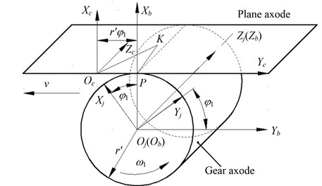
Coordinate relationship between the rack cutter and involute beveloid gear is illustrated in Fig. 4. Sb(Xb,Yb,Zb) is a spatial fixed coordinate system. Sj(Xj,Yj,Zj) is a moving coordinate system attached to gear blank (involute beveloid gear), which forms an angle φ1 with respect to the coordinate system Sb(Xb,Yb,Zb).
Fig. 4Coordinate relationship between rack cutter and involute beveloid gear
The angular velocity vector revolving around the Zj axis of involute beveloid gear can be represented as:
Assuming that the position vector of one point K on rack cutter is described as:
Then we can obtain that:
Combining Eqs. (8) and (10), the relative velocity vector of one point K on rack cutter is:
According to differential geometry and the kinematics of gear geometry [12], the continuous tangency is detected by the equation of meshing which is formulated as:
where the unit normal vectors of rack cutter nK is nK=(nKxnKynKz)T.
Then the motion parameter (rotation angle) for involute beveloid gear generation is:
Substituting Eqs. (6) and (7) into Eq. (13) enables us to solve the rotation angle of straight edge BC and tool fillet curve AB for rack cutter:
2.4. Tooth profile equation of involute beveloid gear
In coordinate system Sj, the tooth surface equation of involute beveloid gear is expressed as:
where Mjc is coordinate transformation matrix.
Similarly, we can also obtain the fillet equation of involute beveloid gear:
Hence, the mathematical models of the involute beveloid gear have been derived.
3. Mathematical model of noninvolute beveloid gear pair
3.1. Coordinate transformation
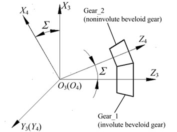
According to the differential geometry and the kinematics of gear geometry, the tooth profile equation and meshing equation of noninvolute beveloid gear can be mathematically generated from a mutually conjugate involute beveloid gear. Fig. 5 describes the relationship between involute beveloid gear cutter and gear blank (noninvolute beveloid gear), including the involute beveloid gear Gear_1, the noninvolute beveloid gear Gear_2 and the intersection angle Σ.
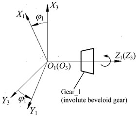
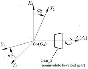
The coordinate system S3(X3,Y3,Z3) and S4(X4,Y4,Z4) are fixed coordinate systems linked with Gear_1 and Gear_2, respectively, and the coordinate system S1(X1,Y1,Z1) and S2(X2,Y2,Z2) are motion coordinate systems joined to Gear_1 and Gear_2, respectively as illustrated in Fig. 6.
Fig. 5Position relationship between the involute beveloid gear cutter and gear blank
Under the initial position, the coordinate system S1 overlaps with S3 and the coordinate system S2 coincides with S4. The Gear_2 rotates clockwise around the Z4 axis with an angle φ2, while the Gear_1 is revolving clockwise around the Z3 axis with an angle φ1.
Fig. 6Coordinate systems of Gear_1 and Gear_2
Consequently, coordinate transformation matrix M21, which is utilized to perform the kinematical relationship between the involute beveloid gear cutter and the generated gear (noninvolute beveloid gear), can be expressed as M21=M24M43M31, where:
M31=[cosφ1-sinφ100sinφ1cosφ10000100001].
3.2. Relative velocity and unit normal vectors of involute beveloid gear cutter
Assuming that angular velocity vector clockwise revolving around the axis of Gear_1 is ω1 and the angular velocity vector anticlockwise revolving around the axis of Gear_2 is ω2. Consequently, the angular velocity vector can be represented based on three components of unit vector in coordinate system S3(X3,Y3,Z3):
The position vector of one contact point M is described as:
Then the relative velocity at the point M can be expressed as:
Substituting Eqs. (18) and (19) into Eq. (20) enables us to obtain the relative velocity:
Substituting i21=ω2/ω1 into Eq. (21), v312 can be further written as:
As a consequence, the relative velocity in coordinate system S1 can be obtained as follows:
where matrix M13 describes coordinate transformation from S3 to S1;(X1,Y1,Z1) means coordinate value of contact point M in coordinate system S1, and (i1,j1,k1) represents three components of unit vector in coordinate system S1.
According to the position relationship between the involute beveloid gear cutter and noninvolute beveloid gear as shown in Fig. 5, the tooth surface of involute beveloid gear cutter in coordinate system S1 can be derived as follows:
where L is coordinate value on the Z1 axis.
Hence, the unit normal vector of Gear_1 (involute beveloid gear) is represented as:
3.3. Meshing equation and tooth surface equation of noninvolute beveloid gear
According to the kinematics of gear geometry, the equation of meshing is defined as:
Combining Eqs. (23), (25) and (26), we can obtain the meshing equation:
where φ1 is angle parameter, which can be derived as:
herein:
c=(1+i21cosΣ)(X1n1y-Y1n1x).
Then the tooth profile equation of noninvolute beveloid gear can be obtained by coordinate transformation from S1 to S2:
As a consequence:
Hence, the mathematical model of involute beveloid gear have been derived.
4. Modeling of involute and noninvolute beveloid gear pair
The main design parameters of involute beveloid gear pairs (pinion and wheel) are: number of teeth Z1/Z2=26/51, normal pressure angle αn1/αn2= 17.5°, normal module mn1/mn2= 5 mm, tooth width b1/b2= 94 mm/89 mm, helical angle β=8°, shaft intersection angle δ=10°; the main design parameters of noninvolute beveloid gear pairs (pinion and wheel) are: number of teeth Z'1/Z2= 26/51, the normal module mn1/mn2= 5 mm, the tooth width b1/b2= 94 mm/89 mm and shaft intersection angle δ=10°.
The parametric modeling program is developed via a Matlab code to generate exact three-dimensional (3-D) discrete points on the tooth profiles. The Fig. 7(a) shows the discrete points on tooth surfaces of involute beveloid gear (wheel). Then the tooth surfaces of involute beveloid gear pair are established after we imported point set into Imageware software. Subsequently, the solid model will be created by importing tooth surfaces into UG to sew up. In this way, we can obtain the accurate three-dimensional solid model as shown in Fig. 7(b).
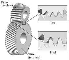
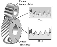
Applying the assembly relationship together with the mathematical models of beveloid gear pairs, the assembly models of involute and noninvolute beveloid gear pairs are generated as illustrated in Fig. 8.
Fig. 7Models of involute beveloid gears
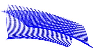
a) Discrete points on tooth surface
b) Solid models
Fig. 8Assembly model of involute and noninvolute beveloid gears
5. Dynamic contact analysis of involute and noninvolute beveloid gear pair
5.1. Finite element model
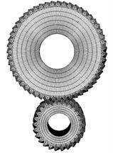
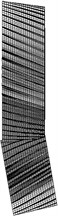
Dynamic contact characteristics of the involute and noninvolute beveloid gear pair will be analyzed by LS-DYNA software. The pinion is rotating at 1600 rpm with a driving torque of 1194 N·m in numerical simulation analysis. The finite element meshes of gear pair are generated using solid element Solid164. In order to conveniently load the speed and torque [13], internal surfaces of gear pair are considered as rigid regions utilizing the Shell163 element. Afterwards, degrees of freedom of all nodes in rigid region are coupled to the centroid of rigid body, and apart from axial rotation, all translational and rotational degrees of freedom of rigid shell elements in pinion and wheel are constrained. The total number of elements is 82160 with 97608 nodes for the finite element model of involute beveloid helical gear pair, shown as Fig. 9.
Fig. 9Finite element model of involute beveloid helical gear pairs
5.2. Simulation results and discussion
Fig. 10 and Fig. 11 describe the dynamic contact stress contour and single tooth contact force of involute and noninvolute beveloid gear during the mesh cycle.
The results show that the contact area on flank of noninvolute beveloid gear is evidently larger than that of involute beveloid gear; the dynamic contact stress distribution of noninvolute beveloid gear is more homogeneous and the contact stress reduces significantly; the contact ratio of noninvolute beveloid gear is 3.74, greater than that of involute beveloid gear, which is 3.30; compared with the single tooth contact force of involute beveloid gear, the noninvolute beveloid gear has smaller single tooth contact force and smoother meshing impact.
Fig. 10Dynamic contact stress contour (Unit: Pa)
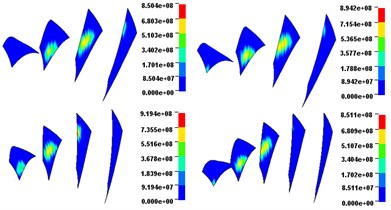
a) Involute beveloid gears
b) Noninvolute beveloid gears
Fig. 11Contact force of each mating teeth pair
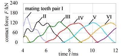
a) Involute beveloid gears
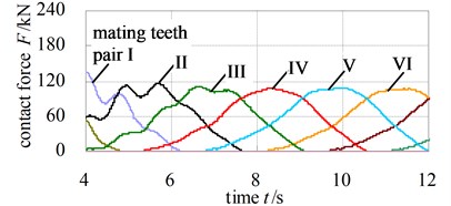
b) Noninvolute beveloid gears
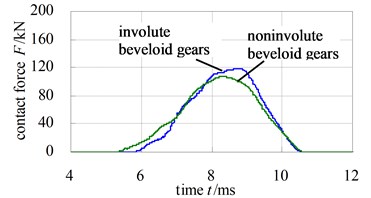
c) Comparison of single tooth contact force
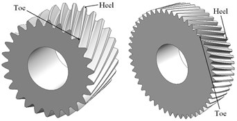
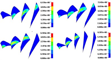
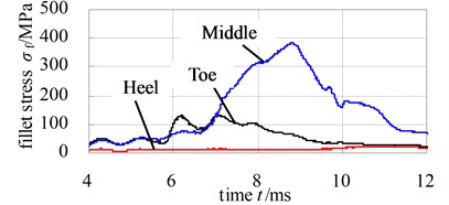
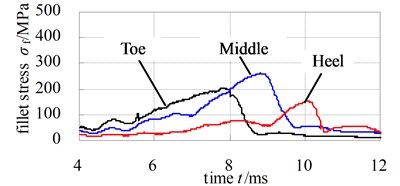
Fig. 12 and Fig. 13 illustrate the dynamic fillet stress of involute and noninvolute beveloid gear, respectively. The results indicate that the dynamic fillet stress of involute beveloid gear mainly concentrate on the mid tooth and toe, by contrast, the heel almost do not bear fillet stress; the dynamic fillet stress distribution of noninvolute beveloid gear is more homogeneous on mid tooth, toe and heel.
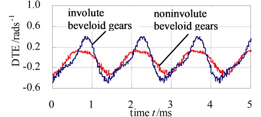
Forecasting the dynamic transmission error (DTE) which is an important factor to cause the vibration, is another objective of dynamic contact analysis. The dynamic transmission error is usually expressed as:
where n1 and n2 is the driving and driven shaft’s rotational speeds with i being the transmission ratio of the gear set, respectively.
Fig. 12Dynamic fillet stress curves of involute beveloid gear pairs
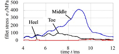
a) Pinion
b) Wheel
Fig. 13Dynamic fillet stress curves of noninvolute beveloid gear pairs
a) Pinion
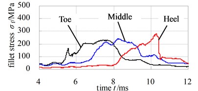
b) Wheel
Fig. 14 illustrates the DTE of involute and noninvolute beveloid gear. As observed in Fig. 14, the predicted DTE is approximate sine shape and the trend of peak-peak value of DTE for involute beveloid gear becomes higher than that of noninvolute beveloid gear due to smaller contact area for involute beveloid gear.
Fig. 14DTE of involute and noninvolute beveloid gear
6. Conclusions
1) The mathematical models of involute and noninvolute beveloid gears are derived and the parametric modeling programs of involute and noninvolute beveloid gears are developed to automatically generate exact model via Matlab code; then a numerical example of intersecting axes beveloid gear pair is presented to analyze the dynamic contact characteristics.
2) The contact area on flank of noninvolute beveloid gear is evidently larger than that of involute beveloid gear, and the dynamic contact stress distribution of noninvolute beveloid gear is more homogeneous and the contact stress reduces significantly.
3) The dynamic fillet stress of involute beveloid gear mainly concentrate on the mid tooth and toe, by contrast, the heel almost do not bear fillet stress, the dynamic fillet stress distribution of noninvolute beveloid gear is more homogeneous on mid tooth, toe and heel.
4) The DTE is approximate sine shape and the trend of peak-peak value for involute beveloid gear becomes higher than that of noninvolute beveloid gear due to smaller contact area for involute beveloid gear and the noninvolute beveloid gear has gentler meshing impact.
5) Hopefully, noninvolute beveloid gear pairs would relieve the high dynamic contact shock problem of intersecting axes beveloid gear pairs and improve range of application.
References
-
Zhang Y.,Fang Z. Analysis of tooth contact and load distribution of helical gears with crossed axes. Mechanism and Machine Theory, Vol. 34, Issue 1, 1999, p. 41-57.
-
Komatsubara H., Mitome K., Ohmachi T. Development of concave conical gear used for marine transmissions. JSME International Journal, Series C: Mechanical Systems, Machine Elements and Manufacturing, Vol. 45, Issue 1, 2002, p. 371-377.
-
Brauer J. Analytical geometry of straight conical involute gears. Mechanism and Machine Theory, Vol. 37, Issue 1, 2002, p. 127-141.
-
Brauer J. A general finite element model of involute gears. Finite Elements in Analysis and Design, Vol. 40, Issue 13-14, 2004, p. 1857-1872.
-
Brauer J. Transmission error in anti-backlash conical involute gear transmissions: a global – local FE approach. Finite Elements in Analysis and Design, Vol. 41, Issue 5, 2005, p. 431-457.
-
Liu C. C., Tsay C. B. Contact characteristics of beveloid gears. Mechanism and Machine Theory, Vol. 37, Issue 4, 2002, p. 333-350.
-
Liu C. C., Chung B. Mathematical models and contact simulations of concave beveloid gears. Journal of Mechanical Design, Transactions of the ASME, Vol. 124, Issue 4, 2002, p. 753-760.
-
Chen Y. C.,Liu C. C. Contact stress analysis of concave conical involute gear pair with non-parallel axes. Finite Elements in Analysis and Design, Vol. 47, Issue 4, 2011, p. 443-452.
-
Chen Chen-Jia, Liu Wen, Lin Teng-Jiao, et al. Modeling of involute beveloid helical gears with intersection axes based on transverse profile of counterpart rack. Chinese Journal of Mechanical Research and Application, Vol. 26, Issue 125, 2012, p. 1-7.
-
Wu S. H., Tsai S. J. Contact stress analysis of skew conical involute gear drives in approximate line contact. Mechanism and Machine Theory, Vol. 44, Issue 9, 2009, p. 1658-1676.
-
Li Gui-Xian, Wen Jian-Min, Li Xiao, et al. Axial errors and profile errors of noninvolute bevoloid gears. Chinese Journal of Harbin Engineering University, Vol. 24, Issue 3, 2003, p. 302-304, 316.
-
Litvin F. L.,Fuentes A. Gear Geometry and Applied Theory. Cambridge University Press, New York, 2010.
-
Lin Teng-Jiao, Ou Heng-An, Li Run-Fang A finite element method for 3D static and dynamic contact/impact analysis of gear drives. Computer Methods in Applied Mechanics and Engineering, Vol. 196, Issue 9-12, 2007, p. 1716-1728.
About this article
The authors are grateful for the financial support provided by the National Natural Science Foundation of China under Contract No. 51175524 and National Science and Technology Support Project under Contract No. 2013BAF01B04.
