Abstract
In order to effectively simulate the nonlinear hysteresis behavior of reinforced concrete (RC) bridge piers under strong earthquake excitation, an improved nonlinear hysteresis model for RC bridge piers was developed and its controlling parameters were determined considering stiffness and strength degradation and pinching effect based on classical Bouc-Wen model. The improved model can be carried out to predict the nonlinear hysteresis behavior of RC bridge piers under various failure modes using MATLAB/ Simulink program. Cyclic tests of different failure mode bridge column specimens were performed under constant axial load with lateral bending. The results did show that force-displacement relationship curves of bridge column specimens derived from theoretical analysis agree well with experimental results. The nonlinear hysteresis behavior of bridge column specimen was simulated under 2008 Wenchuan earthquake excitation and its failure modes were identical with real earthquake damage of bridge column. The improved analytical models in the paper were applied to accurately predicting the nonlinear hysteresis behavior of RC bridge columns with strength and stiffness degradations and the pinching effect subjected to strong earthquake motion.
1. Introduction
Many engineering structures may experience non-elastic states and perform hysteresis behaviors under dynamic loads. Hysteresis, known as elastic-plasticity, is usually derived from nonlinear characteristics of material, the friction characteristics and deformation of the contact surface. Hysteresis relationship exists between the resilience and displacement of structures under load effects. With cyclical loads, the curves of loading and unloading will form the hysteresis loops.
Due to the complexity of the hysteresis curves, it is difficult to be applied for the nonlinear characteristics analysis for structures, which needs a mathematical model with simple description to predict the nonlinear dynamic response of structures. Various hysteretic models have been developed in the past few decades to describe the complex nonlinear hysteresis characteristics of structures. According to the smoothness of hysteretic loop, the models can be generally classified into two types, polygonal hysteretic model and smooth hysteretic model [1]. Polygonal hysteretic model uses piecewise linear mathematical description to reflect the loading and unloading rules of restoring force curves obtained by experiments, such as bilinear model, Clough model [2], Takeda model [3], Q model developed by Saiidi et al. [4], and so on. These model shave been widely used in practical engineering for convenience of the simplicity in stiffness calculation. However, there is turning point or mutation point due to discontinuous change of the stiffness, which will produce cumulative error and is not consistent with the actual situation. It is not convenient to apply and lack of generality consideration strength and stiffness degradation and pinching slip effects, and so on. Hysteretic smooth model, one of the most popular models is a differential model originally developed by Bouc [5] and extended by Wen [6, 7] and Baber [8] which can represent many commonly observed types of hysteretic behavior. The stiffness change of this model is continuous, which is closer to the actual project, and the shortfall is that the stiffness calculation method is more complex. With computing capabilities increased, computational efficiency and accuracy of the smooth hysteretic model has improved greatly, so Bouc-Wen classical model has been widely used in the field of structural engineering.
Bridge piers, acting as the important bridge component supporting the superstructure and transferring the upper load to the foundation, are vulnerable in earthquakes. So the bearing capacity and deformation of the bridge piers directly affect seismic performance of bridge structures. Especially, how to exactly describe the nonlinear hysteretic behavior of the RC bridge pier is the focus issue for seismic analysis of bridge structures. The structural strength and stiffness are influenced by the results of RC material nonlinearity, opening and closing of cracks in concrete, pulling out of steel reinforcement from the concrete matrix, etc., which lead to the complex characteristics of the force-displacement hysteretic curves of the RC piers. The main objectives of this paper are: (1) to develop an improved Bouc-Wen model with the consideration of stiffness degradation, strength degradation and pinching effects for RC piers and to simulate hysteretic characteristics for RC piers with different failure modes through parameters identification; (2) to compare the hysteretic curves of RC bridge piers from tests with those of numerical simulation and to verify the effectiveness of the improved model; (3) to employ this model to investigate the hysteresis behavior of bridge piers under real earthquake motion.
2. Improved Bouc-Wen model
2.1. Initial Bouc-Wen model
Wen modified the initial Bouc model which was differential controlled and smooth hysteretic, known as the initial Bouc-Wen model. Single degree of freedom (SDOF) hysteretic system can be expressed in Fig. 1.
Fig. 1SDOF hysteresis model
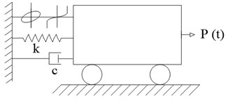
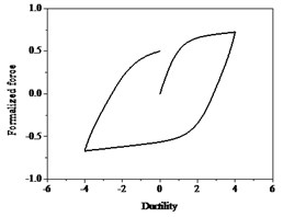
Fig. 2Bouc-Wen hysteresis curve
The model is expressed as Eq. (1):
where m is the mass of system; ke is initial elastic stiffness of the system; c is the structure inherently linear viscous damping; α is the ratio of post-yield to pre-yield stiffness, u, ˙u, ¨u are the system displacement, velocity and acceleration, respectively, z is the hysteresis displacement, the properties of z depend on the material properties, structural properties and the response amplitude.
In order to study the hysteretic characteristics and improve the accuracy of parameter identification, normalized data is used and dimensionless hysteresis curve is shown in Fig. 2. Note that ductility is the ratio of the lateral displacement and yield displacement. The restoring force F is expressed as:
where the derivative of the displacement hysteresis z can be obtained by Eq. (3):
where A is the model parameter, subsequently proved to be unnecessary [9]; β is the parameter of shape control; γ is the parameter of controlling loop size; n is the parameter of controlling loop smoothness. Generally, A, β, n takes a positive number, while γ can take either positive or negative [10].
2.2. The modified model considering degradation and pinching effects
Baber et al. [7, 8] introduced two new functions to the initial Bouc-Wen model, which can take strength deterioration and stiffness degradation in to account. The derivative of the displacement hysteresis z can be gotten using Eq. (4):
where η(ε) is the function of stiffness degradation and ν(ε) is the function of strength deterioration.
The hysteretic energy dissipation can be expressed by the area of enclosed hysteretic loop, which is an effective way to reflect the cumulative damage. The cumulative hysteretic energy can quantify the Bouc-Wen model with stiffness and strength degradation. Hysteresis dissipation energy of unit mass, which equals to absorbed energy, is calculated by the following Eq. (5) [11]:
where η(ε), ν(ε) varies with E(t), z decrease as ν(ε) and η(ε) increases.
Stiffness and strength degradation effects of unloading and reverse reloading are related to energy consumption and cumulative damage, so η(ε), ν(ε) are defined as linear functions of the absorbed energy, expressed [12] as Eqs. (6) and (7):
Rules of sine function loading for the system are as follows. When considering strength degradation only, the hysteresis curves shown in Fig. 3, the slopes of loading and unloading of each loop are the same and the maximum strength of each hysteresis loop decreases progressively. However, when considering stiffness degradation only, as shown in Fig. 4, the stiffness decreases as the number of hysteresis loops increase at the same displacement deformation. When both strength degradation and stiffness degradation are incorporated, the force-ductility curves shown in Fig. 5, the strength deterioration and stiffness degradation are obviously observed.
The inelastic response of RC bridge piers under earthquake excitations may be accompanied by stiffness degradation, strength degradation and pinching effects according to the characteristics of the structure, because of that, the hysteretic model is necessary to consider the degradation and pinching effects. The pinching effects of hysteretic model for RC bridge piers attribute to many reasons, such as opening and closing of cracks in concrete and rebar slipping and so on.
Fig. 3Hysteresis loops with strength degradation
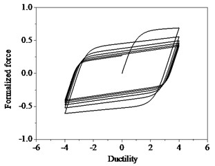
Fig. 4Hysteresis loops with stiffness degradation
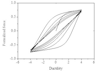
Fig. 5Hysteresis loops with degradation and stiffness degradation and pinching
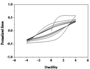
Baber and Noori further developed a generalized hysteretic model to incorporate pinching effects, which implement the smooth hysteretic element in series with a time dependent slip-lock element. As shown in Fig. 6, the displacement of the pinching hysteretic system is divided into two parts, one part is that of smooth degradation model, and the other part is that of slip-locking element, differential form can be expressed as:
The model to describe hysteresis with pinching effects is given by Eq. (9):
Then, the final form of the model can be expressed as [13]:
where the function h(z,ε) is given as:
where ζs is the measure of total slip, q is the initial amount of pinching, p is pinching slope, ψ is a parameter that contributes to the amount of pinching, δψ is a constant specified for the desired rate of pinching spread, λ is pinching ratios.
Fig. 6Slip-lock series element for pinching hysteresis: a) Initial Bouc-Wen model, b) Slip-lock element, c) Improved hysteretic model

As shown in Fig. 7, the hysteretic curves take into account of strength deterioration, stiffness degradation and pinching effects. The relationship of hysteresis restoring force and ductility is more in line with that of the bridge piers under seismic action. Reasonable parameters can simulate a variety of RC piers under complex states, and be applied in the nonlinear seismic response analysis of RC bridge piers in practice.
Fig. 7Hysteresis loops with degrading
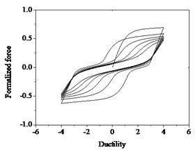
Due to the nonlinearity and complexity of differential equations of Bouc-Wen model, the Simulink module of Matlab program is used to complete the differential equations in this study.
3. Parameters analysis of the shape of hysteresis loops
In Bouc-Wen model, the relationship between restoring force and deformation can be expressed as nonlinear differential equations with uncertain parameters. Among the results of the parameters, reasonable one can be found to simulate nonlinear hysteretic behaviors of the structure or components in practical engineering.
12 of the 14 unknown parameters are used to describe the characteristic of hysteresis model in Bouc-Wen model, except parameters c, k which describe the characteristics of the structure itself. This study finds that 12 parameters have different influence on the shape of hysteresis curves.
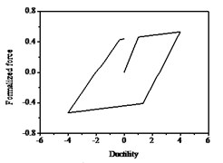
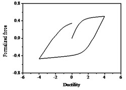
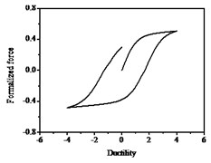
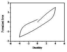
As shown in Fig. 8, the smooth hysteresis loop becomes gradually linear as the values of n increase. The hysteresis loop is bilinear when reaches infinity. It illustrates that n mainly controls the smoothness of the hysteresis curves and it has rarely no impact on the max values of restoring force. As shown in Fig. 9, the characteristics of hysteresis restoring force of the system show soft or hard with different values of β and γ. It seems like soft which shows in the figures that the slopes of hysteresis loop become smaller when the value of β/γ is positive. While the hard means the slopes of hysteresis loop become larger when the value of β/γ is negative. The area of the hysteretic loops becomes gradually larger as the values of β/γ increases, which indicates that the system dissipates more energy during vibration. On the contrary, the area of the hysteretic loops is smaller as the values of β/γ decreases, and the system consumes less energy during vibration. The system is linear and the area of the hysteresis loop is zero for β=0, γ=0, which means the system do not dissipate energy, so the restoring force and displacement reach the maximum values. The parameters β,γ directly impact the nonlinear stiffness and nonlinear damping characteristics. The dissipation energy of the system with β<γ is larger than that with β>γ, and γ can be negative.
With the values of γ decrease, the shape of hysteresis loop varies from that of tan similarity to y=x3 similarity gradually. When the values of γ is negative, the curve shape is elongated, and the restoring force significantly increases in the same displacement value, which works for RC bridge piers under bending loads. The area of the hysteresis loop continuously minishes as the values ofβ decrease, which means that the energy dissipation decreases. When β<0, the system response is not convergence, and cannot get the system hysteresis loop.
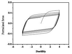
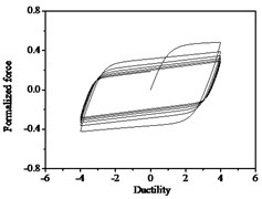
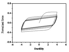
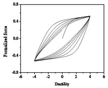
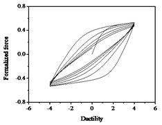
It can be seen from Fig. 10 that the strength degradation increases with the increase of strength degradation parameter δv. As plotted in Fig. 11, the degree of stiffness degradation of each hysteresis loop increases as the stiffness degradation parameter δη increases, which is the slope of the loops decrease. Simultaneously, stiffness degradation can cause a certain degree of strength degradation. The presented smooth hysteretic model has 12 parameters, six of which control pinching effects and have clear geometry meanings.
Fig. 8Hysteresis curves variation with parameter n
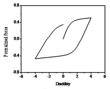
a) n=2
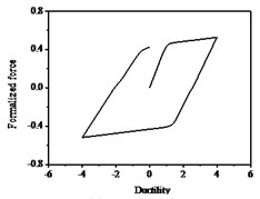
b) n=10
c) n=100
Fig. 9Hysteresis curves variation with parameters β and γ
a) β=0.5, γ=0.5
b) β=0.05, γ=0.95
c) β=0.5, γ=–0.5
Fig. 10Hysteresis curves variation with strength degradation parameter δν
a) δν=0.05
b) δν=0.1
c) δν=0.2
The hysteresis curves present the shape of inverted “S” with the increases of parameter ζs shown in Fig. 12, which indicates there is a big shear and slip effects. The hysteresis curves display obvious pinch phenomenon and the area of the hysteresis loop decreases with the increases of parameter ψ, which indicate the capacity of energy dissipation decreases, as shown in Fig. 13.
Fig. 11Hysteresis curves variation with stiffness degradation parameters δη
a) δη=0.05
b) δη=0.1
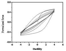
c) δη=0.2
Fig. 12Hysteresis curves variation with parameter ζs
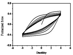
a) ζs=0
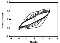
b) ζs=0.4
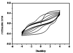
c) ζs=0.8
Fig. 13Hysteresis curves variation with parameter ψ
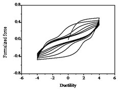
a) ψ=0.1
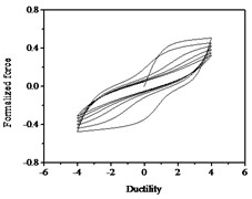
b) ψ=0.2
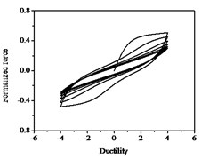
c) ψ=0.4
Fig. 14Hysteresis curves variation with parameter λ
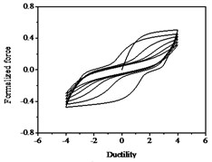
a) λ=0.25
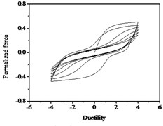
b) λ=0.05
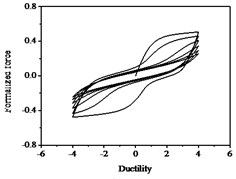
c) λ=1
Fig. 15Hysteresis curves variation with parameter δψ
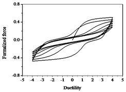
a) δψ=0.005
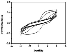
b) δψ=0.01
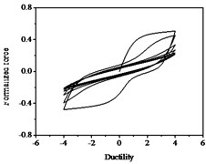
c) δψ=0.02
The parameters λ, δψ and p have less influences on the hysteresis curves according to Fig. 14, Fig. 15 and Fig. 16. The parameter q controls the time of pinching effectsin Fig. 17. The bigger of q, the later of pinching effects come out, the plumper of the hysteretic loops become, the larger of energy dissipation capacity are.
Fig. 16Hysteresis curves variation with parameter p
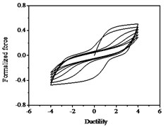
a) p=2.5
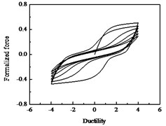
b) p=5
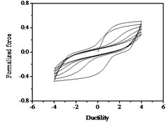
c) p=10
Fig. 17Hysteresis curves variation with parameter q
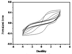
a) q=0.15
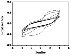
b) q=0.3
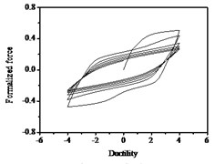
c) q=0.6
4. Numerical simulation and experimental results of comparative analysis
Earthquake damages of RC piers mainly attributes to flexural failure, shear failure, flexural-shear failure, torsion and flexural-torsion failure, and so on. Based on these damage mechanisms, experiments and numerical studies are carried out.
High piers primarily fail during earthquakes due to over flexure moment. The hysteresis loop is plumper for bridge piers with bending failure, which shows better ductility and energy dissipation capacity. Axial compression ratio for high bridge piers is an important factor to hysteretic behaviors. Ductility and energy dissipation capacity decrease with the increase of axial compression ratio, and hysteresis curves present pinching phenomenon. Stiffness and strength degradation are more severe with increase of the displacement amplitude. Besides, longitudinal reinforcements and stirrup ratio are also important factors to impact hysteretic behavior. The hysteresis curves become plumper, and ductility and energy dissipation capacity are improved along with longitudinal reinforcements and stirrup ratio increasing, especially with the stirrup ratio, which can significantly improve the hysteretic behaviors.
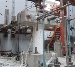
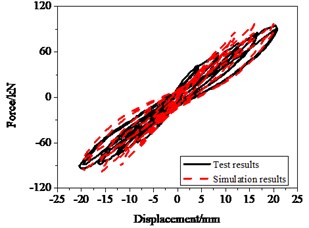
The restoring force is expressed as Eq. (2) under constant axial compression and low cycles loading test. The geometry of the RC bridge piers and the setup are shown in Fig. 18.and Fig. 19, respectively. The cross-section of circular RC columns had diameter of 400 mm, the total height of the column 2350 mm and the effective height measured from the bottom of the column to the loading point 1350 mm. RC column specimens were tested under a constant axial load 0.1 f'cAg; in this series of experiments the longitudinal reinforcement ratio of specimens was 0.015, and volume containing stirrup ratio was 0.006. Fig. 20(a) shows the hysteresis loops of the experimental and numerical analysis. The numerical results including the peak values, stiffness, strength degradation and pinching effects are well fitted the experimental results. The deviation of the maximum values between numerical and experimental is below 10 %.
Fig. 18Specimen geometry and reinforcement
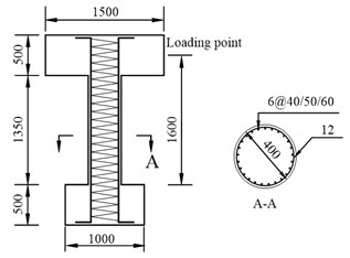
Fig. 19The photo of specimen loading
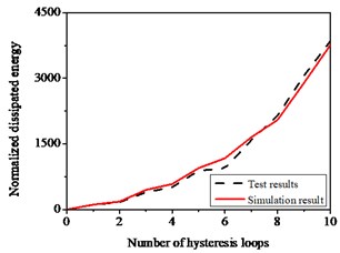
Energy dissipated as an important seismic performance indicator can be applied to verify the effectiveness of the developed model. Fig. 20(b) shows the comparison of the experimental energy dissipated with simulation results, the hysteresis loop gradually becomes full, which verifies that simulated results are well fitted with those of experiments.
Fig. 20Hysteresis behavior of RC columns under bending effect: a) The test and numerical simulation results, b) Cumulative energy dissipation
a)
b)
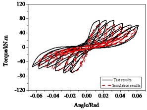
Torsion tests for RC bridge piers showed that the hysteresis curves obtained display the reverse “S” shape and are relatively full. Damage of the rebar and concrete bonding occurs easily under torsion failure, which results in more severe stiffness and strength degradation and concrete cracking for bridge piers, even pinching phenomenon after cyclic open-close of the cracks and slips of the bonding.
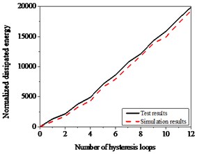
The geometry and steel-bar-reinforcement layout of specimens subjected to torsion are the same with those of bending. The hysteretic curves display obvious pinching effects as shown in Fig. 21(a). The numerical curves, dotted curves in Fig. 21(a), are obtained through parameter identification, which approach with satisfactory results comparison with experimental results, especially pinching effects. In Fig. 21(b), the deviations of energy dissipated between simulation and experiment do not exceed 20 %.
Bending destroy was mainly found in the specimens with larger shear span ratio, smaller axial compression ratio and the reasonable reinforcement, which primarily lead to bending deformation. Shear failure, the characteristics of shear deformation and fragility, occurred before longitudinal reinforcement yield, which was observed mainly in the specimens with smaller shear span ratio, larger axial compression ratio and smaller stirrup ratio. Flexural-shear failure is somewhat similarity between shear failure and the bending failure. In the beginning of damage, it is similar to bending failure with less stiffness and strength degradation. When shear cracks developing and strength reaching the ultimate value, the stiffness and strength degradation had been already large, which made shear capacity of the piers decreased with increase of the deformation. While the process of bending-shear failure is more complex, there was few studies work on it.
Fig. 21Hysteresis behavior of RC columns under torsion effect: a) The test and numerical simulation results, b) Cumulative energy dissipation
a)
b)
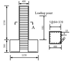
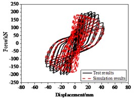
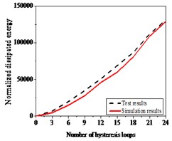
The layout of the RC bridge piers for bending-shear failure is shown in Fig. 22(a). And the axial compression ratio of the specimen was 0.65, the longitudinal reinforcement ratio of specimens 0.0158; volume containing stirrup ratio 0.0079, and shear span ratio 2.64. As Fig. 22(b) showed the hysteresis curves obtained from numerical simulation are consistent with those from experiment, with a deviation of 15 %, especially the stiffness and strength degradation after yield. Comparison of energy of test results and numerical simulation is shown in Fig. 22(c), and the error is less than 20 %.
Fig. 22Hysteresis behavior of RC columns under bending load under bending-shear effect: a) Specimen geometry and reinforcement, b) The test and numerical simulation results, c) Cumulative energy dissipation
a)
b)
c)
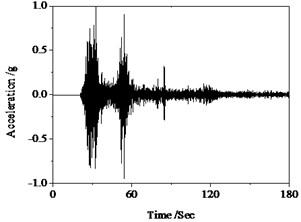
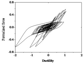
Fig. 23Hysteresis behavior of RC columns under torsion effect: a) Wenchuan earthquake wave, b) Hysteresis loops
a)
b)
The above numerical results can be drawn that the improved Bouc-Wen model can well simulate the hysteresis characteristics of RC pier subjected to the quasi-static loads. In order to verify applicability and versatility of the improved Bouc-Wen model, it is employed in the analysis under seismic excitation. The same specimens with the bending test are selected. The earthquake motion as an external stimulus and the sampling interval is 0.02 s, shown in Fig. 23(a). The hysteresis curves obtained from numerical simulation tend to be full and nonlinear damage constantly accumulates with the external excitation continues, shown in Fig. 23 (b). Therefore, the given model can well simulate the characteristics of temporal evolution of nonlinear damage for structures under earthquake excitations.
5. Conclusions
An improved nonlinear hysteresis model for RC bridge piers is developed considering stiffness and strength degradation and pinching effect based on classical Bouc-Wen model. The various controlling parameters for the improved model are determined, and the improved model can be carried out to predict the nonlinear hysteresis behavior of RC bridge piers and various failure modes using MATLAB/Simulink program. The results of cyclic tests of bridge column specimens with different failure modes show force-displacement relationship hysteresis curves of bridge column specimens derived from theoretical analysis are well agree with experimental results. So the developed analytical models in the paper can be applied to accurately predicting the nonlinear hysteresis behavior of RC bridge columns subjected to strong earthquake excitation.
References
-
Sivaselvan M., Reinhorn A. Hysteretic models for deterioration inelastic structures. ASCE Journal of Engineering Mechanics, Vol. 126, Issue 6, 2000, p. 633-640.
-
Clough R. W. Inelastic earthquake response of tall buildings. Proceedings of the 3rd World Conference on Earthquake Engineering, New Zealand, 1965, p. 68-89.
-
Takeda T., Sozen M. A., Nielsen N. N. Reinforced concrete response to simulated earthquakes. ASCE Journal of Structural Division, 1970, p. 2557-2573.
-
Saiidi M., Sozen A. Simple nonlinear seismic analysis of RC structures. Journal of Structural Engineering, Vol. 107, Issue 5, 1981, p. 937-952.
-
Bouc R. Force vibration of mechanical systems with hysteresis. In Proceedings of the Fourth Conference on Nonlinear Oscillation, Prague, Czechoslovakia, 1967, p. 315.
-
Wen Y. K. Method for random vibration of hysteretic systems. Journal of Engineering Mechanics, Vol. 102, Issue 2, 1976, p. 249-263.
-
Baber T. T., Wen Y. K. Random vibrations of hysteretic degrading systems. Journal of Engineering Mechanics. Journal of Engineering Mechanics, Vol. 107, Issue 6, 1981, p. 1069-1089.
-
Baber T. T., Noori M. N. Random vibration of degrading pinching systems. Journal of Engineering Mechanics, Journal of Engineering Mechanics, Vol. 111, Issue 8, 1985, p. 1010-1026.
-
Ma F., Zhang H., Bockstedte A., Foliente G. C., Paevere P. On parameter analysis of the differential model of hysteresis. Journal of Applied Mechanics, Vol. 71, Issue 3, 2003, p. 257-268.
-
Baber T. T., Noori M. N. Modeling general hysteresis behavior and random vibration applications. Journal of Vibration, Acoustics, Stress and Reliability in Design, Vol. 108, Issue 4, 1986, p. 411-420.
-
Li H., He X., Meng G. The search of Bouc-Wen hysteretic system dynamic simulation. Journal of System Simulation, Vol. 16, Issue 9, 2004, p. 2009-2011.
-
Wu M., Smyth A. Real-time parameter estimation for degrading and pinching hysteretic models. International Journal of Nonlinear Mechanics, Vol. 43, Issue 9, 2008, p. 822-833.
-
Foliente G. C. Hysteresis modeling of wood joints and structural systems. Journal of Engineering Mechanics, Vol. 121, Issue 9, 1995, p. 1013-1022.
About this article
This research is jointly funded by the National Natural Science Fund of China (NSFC) (Grants No. 51178008, No. 51378033), the National Program on Key Basic Research Project (Grant No. 2011CB013600) and the research project of Beijing Municipal Commission of Education (Grant No. KZ201410005011). Their supports are gratefully acknowledged.
