Abstract
According to the ASME-359 code, a scaled-down structure of Reinforced Concrete Containment Vessel (RCCV) of Advanced Boiling Water Reactor (ABWR) building is constructed for the seismic test on the shaking table. Several acceleration time history satisfing design response spectrum with different magnitudes are used in the test. Besides, the numerical finite element model of RCCV is built by SAP2000 for calculating the dynamic responses numerically.
1. Introduction
After the disaster of nuclear power plant (NPP) in Fukushima Daiichi, the safety of nuclear energy becomes more important. The major function of the reinforced concrete containment vessel is isolating the radioactive materials released from the reactor pressure vessel. Hence, to ensure the safety of RCCV and to make it airtight is paramount missions. However, to make a full-scale model for seismic test is not easy to be realized due to the limited capable of the existing shaking table. For the reason, the assistance of scale-down technique [1] is essential for such huge structure in seismic test. In this study, a scale-down model of RCCV is designed by the ASME-359 code [2] and the main purpose of present test is to confirm the safety and the functionality of concrete structure while the model is subjected to a large seismic loading. The method used for checking the safety and the functionality of concrete structure is to detect the growing of cracks and the detecting implement is ultrasonic sensor. Some researches of structural damage monitoring are shown in the references [3-6]. In additional, the experimental data can be the comparison for the numerical modeling in verification. This test is carried out at National Center for Research on Earthquake Engineering (NCREE) in Taiwan. In order to avoid the natural frequencies of the scaled-down model too high to induce the dynamic responses during the seismic testing, the aspect ratio of this model is higher than that of full-scale model to reduce the frequencies of present scaled-down model. Not only a sine sweep signal but also a fictitious seismic signal is used for the input motions of shaking table. Also, the supersonic detector catches the voices in concrete and determines whether the micro cracks grow or not. Finally, the experimental planning, numerical models and data results will illustrate in this paper.
2. Experiment planning
The scaled-down specimen of RCCV consists of a square foundation, cylinder and top slab with a circular hole (Fig. 1). The dimensions of those components are as following: the length is L=3.7 m and the thickness is tf=0.3 m for the square foundation; the outer diameter is D=2.5 m, the thickness is tc=0.15 m and the is height H=4 m for the cylinder; for the top slab the length is L=3.7 m, the thickness is ts=0.4 m and the diameter of hole is d=0.8 m. Those dimensions are designed from the stress analysis of the numerical model (Fig. 2) according to the ASME-359 code [1], where the strength of the model is set to bear the 1G ground acceleration. The model is installed on the shaking table by 37 steel screws. The input motions and sensor location of testing will be described in the following.
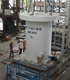
Fig. 1. Scaled-down specimen of RCCV
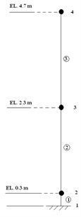
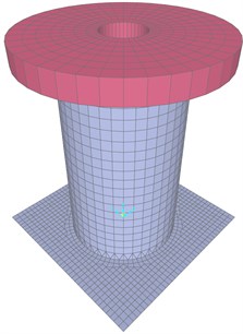
Fig. 2Numerical models of scaled-down RCCV
a)
b)
2.1. Input motion
The fundamental frequency of the model is measured from the sine sweep vibration test where the input wave is 200 gal and the range of which is 1-50 Hz. Further, the acceleration time histories of fictitious seismic input motion in x- and y-direction are plotted in Fig. 3, where the PGA is 0.4 G. The different magnitudes of input motion are produced by multiplying different scaling factors to the one shown in the Fig. 3.
2.2. Sensor installation
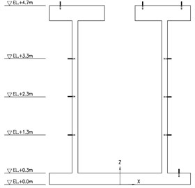
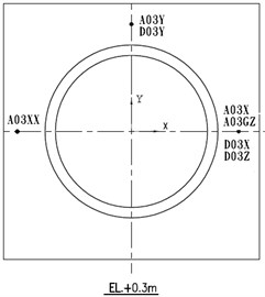
The accelerometers and displacement meters are installed on the model at the elevations related to the bottom of foundation which are 0.3 m, 1.3 m, 2.3 m, 3.3 m and 4.7 m, shown in Fig. 4.
3. Numerical modeling
For the design of scale-down model of RCCV, the two numerical models build by SAP2000 are shown in Fig. 2(a) and Fig. 2(b). One is a lumped-mass stick model, which is a simplified model for preliminary study of modal frequency. The other one is a 3D finite element model for stress analysis and design. The material properties of concrete used in SAP2000 are E=210kg/cm2 and ρ=2.4t/m3, which are Young’s modulus and density.
Fig. 3Acceleration time histories in x- and y-direction
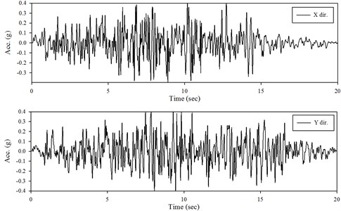
Fig. 4The locations for the installed sensors
3.1. Lumped-mass stick model
For such simplified model, the effect of mass is condensed in the discrete nodes and beams contribute the stiffness of the structure. The properties of mass and rotational inertia of nodes can be calculated by some well-known methods, whereas the stiffnesses of elements are self-produced by giving sections of beam element from SAP 2000 program. The base of this model is fixed and the natural frequencies are listed in Table 1.
Table 1The natural frequencies of numerical models
Mode | Lumped-mass stick model (fixed base) | 3D finite element model (fixed base) | 3D finite element model (spring support) |
1 | 26.8 (X dir.) | 28.9 (X dir.) | 18.6 (X dir.) |
2 | 26.8 (Y dir.) | 28.9 (Y dir.) | 18.6 (Y dir.) |
3 | 104 (Vertical dir.) | 61 (Tourtion dir.) | 60 (Tourtion dir.) |
3.2. Finite element model
To implement the section design for the scale-down model of RCCV, a 3D finite element model is build and shown in Fig. 2(b). The element types of foundation and cylinder are identical, which are shell element, whereas solid elements are used for top slab. Based on the checking steps shown in [1] the calculation of stresses for the foundation, cylinder and top slab under the designed base earthquake loading should be smaller than the allowable stresses. For free vibration analysis, two kinds of constrain are discussed. One is fixed end and the other is spring support, where the spring constant are defined by the use of screws made of steel according to such connecting way presented in this test. The frequencies of the two models, fixed base and spring support one, as also shown in Table 1. To compare the frequencies of the stick model with 3D finite element model, Table 1 shows that there are not much different in fixed base, which means the simplification of the stick model is reliable. From the results in spring support, it can be found that the frequencies in horizontal directions are lower than those of fixed end, which means that the connection by those steel screws is not stiffness enough to simulate the foundation bonded on sharking table perfectly.
4. Results and verifications
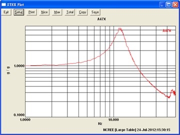
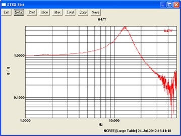
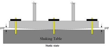
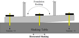
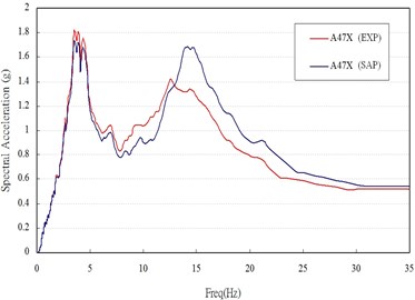
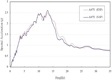
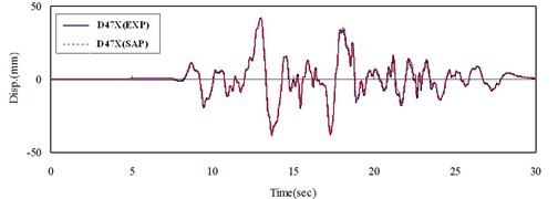
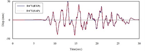
From the sine sweep test, it can be found that the fundamental frequency in x- and y-direction are about 12 and 13 Hz (Fig. 5), respectively, which is different to the values from the numerical results, 18.6 Hz. The reason may be attributed to that the foundation of the model is not flat enough, and then only half of the screws are in function when the foundation is rocking (Fig. 6). Hence, a modification should be done in numerical model, which is giving a discount of 50 percent in the stiffness of spring. By considering this modification, the frequency of the re-model reduces to the value of 13.66 Hz, which matches the one of experiment. Under the seismic loading and modal damping ξx=0.09 and ξy=0.14 used in x- and y-direction, the associated spectral acceleration (damping 5 %), time histories of acceleration and of displacement obtained from experiment and calculated by numerical analysis are plotted in Fig. 7-9. Those figures show that the responses between experiment and numerical model are agree with each other and the modification of stiffness of spring for this case is reasonable.
Fig. 5The first mode frequencies measured from the experiemental data by using transfer function in a) x-direction and b) y-direction
a)
b)
Fig. 6The rocking due to uneven foundation in a) static state condition and b) horizontal shaking condition
a)
b)
Fig. 7Respectral acceleration of experiment and numerical results at point located on the top of slab in a) x-direction and b) y-direction
a)
b)
Fig. 8Time histories of acceleration of experiment and numerical results at point located on the top of slab in a) x-direction and b) y-direction

a)

b)
Fig. 9Time histories of displacement of experiment and numerical results at point located on the top of slab in a) x-direction and b) y-direction
a)
b)
5. Conclusions
According to the ASME-359 code, a scaled-down model of RCCV is design to bear the seismic input motions on shaking table to ensure the safety and functionality of the model by ultrasonic detection. From the results of ultrasonic detection, some very tiny cracks are formed during the test. But such cracks do not affect the function of RCCV. Furthermore, a modification of numerical model is executed to compare the dynamic responses with the one of experimental model. By fitting the numerical dynamic behaviors to the real scaled-down model, the modified numerical model is successful in modeling the experimental model. From the suggestion of R. G. 1.61 [7], the material damping of concrete structure is 4 % for OBE, which is smaller than the values ξx=0.09 and ξy=0.14 used in present numerical model. The additional damping more than 4 % may come from the connection between the scared-down RCCV and the shaking table, where the bond is not perfect and there is a slight friction resulted. From this experience of the scaled-down model for seismic testing, we can know that to ensure the perfectly bond between the model and the shaking table is very important and such check can reduce the uncertainty for the experimental test.
References
-
Noor F. A., Boswell L. F. Small Scale Modelling of Concrete Structures. CRC Press, 1992.
-
ASME/ACI 359 Boiler and Pressure Vessel Code Section III, Rules for Construction of Nuclear Power Plant Components, Div. 2, Subsection CC. Code for Concrete Reactor Vessel and Containments, 2004.
-
Tibaduiza D. A., Torres-Arredondo M. A., Mujica L. E., Rodellar J., Fritzen C. P. A study of two unsupervised data driven statistical methodologies for detecting and classifying damages in structural health monitoring. Mechanical Systems and Signal Processing, Vol. 41, Issues 1-2, 2013, p. 467-484.
-
Kullaa J. Distinguishing between sensor fault, structural damage, and environmental or operational effects in structural health monitoring. Mechanical Systems and Signal Processing, Vol. 25, Issue 8, 2011, p. 2976-2989.
-
Min J., Park S., Yun C. B., Lee C. G., Lee C. Impedance-based structural health monitoring incorporating neural network technique for identification of damage type and severity. Engineering Structures, Vol. 39, 2012, p. 210-220.
-
Ignatovich S. R., Menou A., Karuskevich M. V., Maruschak P. O. Fatigue damage and sensor development for aircraft structural health monitoring. Theoretical and Applied Fracture Mechanics, Vol. 65, 2013, p. 23-27.
-
Regulatory Guide 1.61, Damping Values for Seismic Design of Nuclear Power Plants. U.S. Nuclear Regulatory Commission, Office of Nuclear Reactor Regulation, 2007.
About this article
This support of the National Science Council (NSC) under the Grant NSC102-3113-P042A-009 in Taiwan and National Center for Research on Earthquake Engineering (NCREE) is gratefully acknowledged.
